Insert the drill bit (1) into the upright axle (2) as shown
in the illustration and secure it in place by tightening
the screw (4) into the upper screw hole of the upright
axle (2) using the hexagon key (16) supplied.
Insert the transverse axle (3) into the square aperture
of the upright axle (2) as shown in the illustration.
Align the center hole of the transverse axle (3) with
the screw hole of the upright axle (2) and secure it in
place by tightening the screw (5) into the bottom
screw hole using the hexagon key (16) supplied.
Insert the right (R) cutting blade (6) with it’s R plane
surface facing outwards, into the upper aperture of
the adjustable cutter holder (8) and secure it in place
by tightening the screw (7) using the hexagon key (16)
supplied.
Insert the left (L) cutting blade (6) with it’s L plane
surface facing outwards, into the upper aperture of
the adjustable cutter holder (8) and secure it in place
by tightening the screw (7) using the hexagon key (16)
supplied.
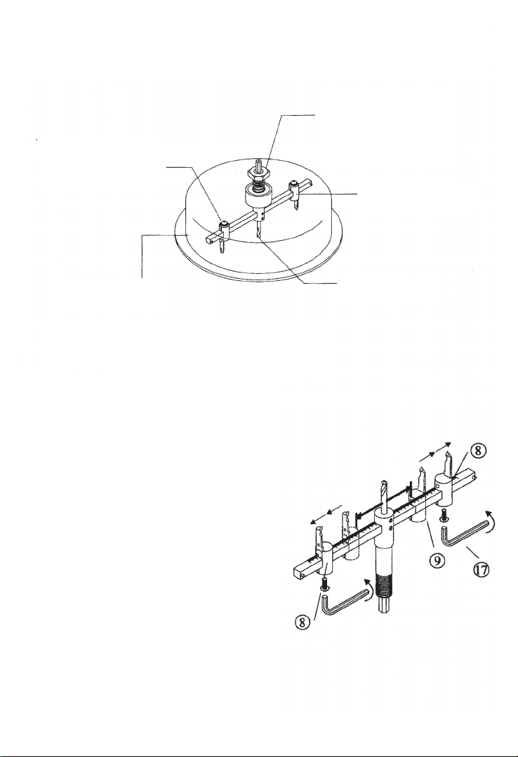
Insert both of the right and left hand adjustable cutter
holders (8) fitted with the right and left cutting blades
respectively into the right and left sides of the
transverse axle (3) and secure them by inserting the
spring pins (10) respectively into the right and left side
pinholes of the transverse axle (3).
Tightening the screws (9) respectively into the screw
holes located at the bottom side of both of the right
and left side adjustable cutter holders (8) using the
hexagon key (17) supplied.
The completed assembly of the internal components
should resemble the illustration shown opposite.
1.
2.
3.
4.
5.
6.
7.
INTERNAL COMPONENTS
ASSEMBLY INSTRUCTIONS