JORESTECH E-IND-35 User manual

JORESTECH®MANUAL INDUCTION SEALING MACHINE
E-IND-35/100HA/130HC
OPERATIONS MANUAL
READ ALL INSTRUCTIONS CONTAINED IN THIS MANUAL PRIOR TO MACHINE INSTALLATION

2
TABLE OF CONTENTS
GENERAL INFORMATION 1
GENERAL SAFETY WARNINGS 1
SPECIFICATIONS 2
OPERATION 2
Sealing Head Selection 2
Sequence of Operation 3
Control Panel 4
MAINTENANCE 4
Routine Inspection and Servicing 4
TROUBLESHOOTING 5
MACHINE PARTS AND DIAGRAMS 6
Machine Breakdown 6
Sealing Head Breakdown 7
Sealing Heads Dimensions and types 8
ADITIONAL INFORMATION 9
Understanding Induction Sealing 9
Understanding The Results of Induction Sealing 10
Cap & Container Issues 13

1
GENERAL INFORMATION
This manual covers safety precautions, parameters, machine operation, maintenance, and
troubleshooting information. The machine shall only be operated by someone over the age of 18,
and not under the influence of any drugs or alcohol. Any modification to the machine voids any
warranty, and may cause harm to individuals using the machine while in operation.
CHECK PACKAGE UPON ARRIVAL
Be extra careful if using a sharp instrument when removing the protective wrapping from the
equipment. Upon receipt of a Manual Induction Sealing, please inspect for external damage, if no
damage is evident on the external packaging, open package to ensure all ordered items are within,
and there is no concealed damage to the machine.
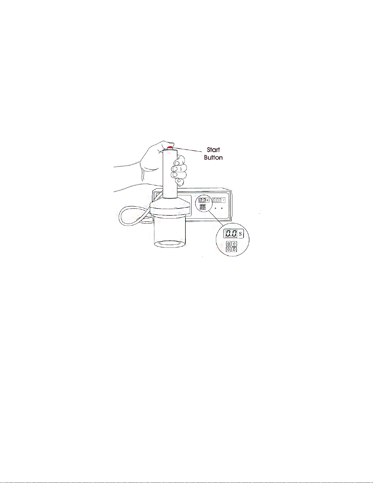
HANDLING
The JORESTECH®Manual Induction Sealing Machine was completely tested and inspected before
being ready for shipment. Like any piece of electronic equipment, it should not be dropped or given
harsh treatment.
GENERAL SAFETY WARNINGS
THIS EQUIPMENT PRODUCES AN ELECTROMAGNETIC FIELD TO FACILITATE THE INDUCTION SEALING
PROCESS. THE ELECTROMAGNETIC FIELD QUICKLY HEATS ANY METAL WITHIN THE FIELD AND MAY,
UNDER CERTAIN CONDITIONS, IGNITE THE METAL OR SURROUNDING MATERIALS.
WARNING: This machine uses voltages that are potentially hazardous. Severe, even life-
threatening, personal injury could result if the instructions contained in this manual are
not followed. Before operating the unit, please read this manual thoroughly. This manual
should be kept for future reference.
⚠DO NOT Reach into the equipment, or any electrical enclosure, without first removing the
power. Always disconnect power before servicing, changing accessories or cleaning the unit
⚠NEVER apply power to this unit without all covers securely in place.
⚠DO NOT Use the unit outdoors.
⚠DO NOT Operate this equipment in a hazardous environment. The presence of High Voltage
within this equipment may result in explosion or fire when operated near flammable vapors,
fuels, or other combustibles.
⚠DO NOT Attempt to seal products with damaged or improperly applied liners, as they may
overheat causing the liner and container contents to ignite.
⚠BEFORE operating the machine, make sure the power supply is correct and is properly
grounded.
⚠DO NOT use the unit if the power cord, plug or any other parts are damaged. To avoid damaging
the electrical cord, keep it out of areas where it can be stepped on.
⚠DO NOT alter or modify the machine’s original design in any way.
⚠NEVER operate or service your unit until you have read this manual. Keep this Operation
Manual with care for easy reference.

2
SPECIFICATIONS
PARAMETERS
E-IND-35
E-IND-100HA
E-IND-130HC
Rated Voltage
120VAC
120VAC
220VAC
Rated Frequency
60Hz
60Hz
50/60Hz
Output Power
500W (0.67HP)
500W (0.67HP)
500W (0.67HP)
Sealing Time Range
0.1 – 9.9 sec
0.1 – 9.9 sec
0.1 – 9.9 sec
Sealing Diameter
15–35mm (0.6-1.4”)
20–100mm (0.8-3.9”)
60–130mm (2.4-5.1”)
Max. Ambient
Temperature
≤45⁰C (113F)
≤45⁰C (113F)
≤45⁰C (113F)
Relative Air Humidity
≤95%
≤95%
≤95%
Housing Protective
Grade
IP21
IP21
IP21
Housing Material
Plastic
Plastic
Plastic
Model Type
Top table
Top table
Top table
Machine Dimensions
(LxWxH)
340x290x130mm
(13.4x11.4x5.1”)
340x290x130mm
(13.4x11.4x5.1”)
340x290x130mm
(13.4x11.4x5.1”)
Gross Weight
5kg
5kg
5kg
OPERATION
The JORESTECH®Manual Induction Sealing Machine Series are compact, but powerful enough to
handle virtually all your induction cap sealing needs. With its advanced electronics and a variety of
sealing heads, these portable units can seal everything from the smallest closures to 120mm wide-
mouth containers. These units require no water cooling, or special power so it can be used virtually
anywhere, and are extremely simple to use.
Induction Sealing is a process used to seal containers hermetically by using an electromagnetic field
to heat a heat-sealable foil liner located within a closure. This electromagnetic field heats the liner
by inducing currents into the metal of the foil liner located within the closures of your containers.
Electrical currents, called “eddy currents”, are induced into the aluminum foil, resulting in a
resistance-type heating effect. The polymer coating melts and flows around the lip of the container,
when the electromagnetic field is shut off the polymer cools and hardens, bonding the foil to the
container lip. When the closure is removed from the container the metal foil will remain bonded to
the lip of the container.
NOTE: A fundamental requirement for induction cap sealing is to have the proper amount of torque
on the cap, which exerts a downward force when sealing.
Sealing Head Selection
The Manual Induction Sealing Machines are designed for different cap sizes. If you need to seal
multiple products, with a varying range of cap and liner sizes, it is possible that you need to select
the machine with the appropriate sealing head dimension according with your production needs. (See
Section: Sealing Heads dimensions and Types)
Each sealing head is designed to allow centering the caps, to achieve better sealing results. The large
sealing head (E-IND-130HC) is supplied with 3 standard size centering rings to aid in properly aligning
the cap under the center of the sealing head. For replace a centering ring, you must unthread the
one in the sealing head and thread and tighten the other one.

3
Sequence of Operation
1- Place the machine on a stable worktable.
2- Connect the power cord to a wall outlet with correct supply voltage.
3- Plug in the machine and TURN ON the main switch on back side of machine. Display must show
the actual input voltage. Check if the voltage is within the correct range for machine
operation.
4- Tightly screw on induction seal cap to jar and center the induction head on top of the cap.
5- Apply a slightly downward pressure on the cap, and press the red start button until the timer in
display reaches zero.
6- Allow cap to cool before handling. Open the bottle to check the sealing conditions. If the sealing
is acceptable then repeat the steps to seal another cap. If not, you must need to adjust the
sealing time accordingly with the size of the cap and type of liner.
NOTE: If the liner looks tight but can be peeled off easily, it is possible that sealing time is
insufficient and you need to increase sealing time. If the liner shows signs of deterioration and/or
wrinkling and the inside of the closure shows signs of melting or burned, means the sealing time
is too long and you need to decrease the sealing time.
NOTE: Timer can be set between 0.1 and 9.9 seconds. To ensure the best seal, unit should be
tested to determine the best time setting according with product.
When the voltage value, shown on display is above 140VAC or below 90VAC (For E-IND-35/100HA)
stop sealing work until voltage returns to normal conditions.
When the voltage value, shown on display, is above 250VAC or below 180VAC (For E-IND-130HC) stop
sealing work until voltage returns to normal conditions.
If the RED Overcurrent light indicator, on the front panel, flickers and sounds a warning tone, means
that output current exceeds the maximum value and the Overcurrent protection function is
activated. In this case Induction work is not effective. Move the induction head from cap surface,
increasing the distance, until the lights turns off.

4
If the temperature of main components inside the machine is too high, the YELLOW light indicator,
on the front panel, will be ON and Overheating protection function activates, inductive output stops
automatically. Sealing shall not be done until temperature drops down and yellow indicators lights
off. Allow unit to cool for 5 minutes after 10 minutes of continuous use.
Control Panel
MAINTENANCE
IMPORTANT: DO NOT Reach into the equipment, or any electrical enclosure, without first
removing the power. Always disconnect power before servicing, changing accessories or cleaning
the unit.
JORESTECH®Manual Induction Sealing Machines are designed to require minimal maintenance.
However, to ensure long-term reliability, it is a good practice to perform some preventive
maintenance actions.
Routine Inspection and Servicing
A weekly visual inspection is a good practice that will often identify issues before they affect the
equipment. You should check for dust and corrosive buildup on the system and hardware. Use low
pressure dry compressed air or a soft brush to remove dust for the machine components.
Inspect any cables or connectors for damage or deterioration. Cables must be free of kinks, cracks,
burns or discoloration along its entire length.
Inspect the sealing head. Make sure that sealing head housing is free of cracks or discolored from
overheating.
Inspect internal connections. Remove the top cover and front and back cover plate. Power and
control connections should remain tight. Loose connections may often be recognized by discoloration
of the wire or connector.

5
TROUBLESHOOTING
MALFUNCTION
POSSIBLE CAUSE
SOLUTION
Machine does not turn ON
Power cord is not plug in into
wall receptacle. Plug in the power cable.
Fuse broken.
Replace the broken fuse.
Main switch damage or broken.
Replace Main power switch.
Control Panel is lit but nothing
happens when start button is
pressed
Broken Start button
Replace Start Button
Damage Sealing Head Replace Sealing head
Work signal indicator is in order
but machine does not seal.
Input voltage out of range
Discontinue use until input
voltage is within operational
range
Insufficient sealing time.
Increase sealing time.
Materials of inductive liner and
sealing object are inconsistent. Choose appropriate materials.
Damage Sealing Head
Replace Sealing Head.
Damage Main circuit board
Replace Main circuit board
Overheating light is ON (yellow
indicator)
High Temperature of main
components
Discontinue use until light turn
OFF.
Overcurrent light is ON (red
indicator) Output current exceeds the
maximum value
Move induction head from jar
and cap surface until light
turns OFF

6
MACHINE PARTS AND DIAGRAMS
Machine Breakdown
Part Number
Description
Quantity
1
Machine Top Cover
1
2
Power plug
1
3/6
Power Fuse
1
4/5
Main Switch
1
7/8
Induction Head Cable Gland
1
9
Back Cover
1
10
Display Board
1
11
Front Cover
1
12
Control Transformer
1
13
Bridge Rectifier
1
14
Control Inductive Reactance
1
15
Main PCB Board
1
16
Power Transistor / Cooling Fan
1
17
Mounting Plate
1
18
Machine Base
1

7
Sealing Head Breakdown
Part Number
Description
Quantity
1
Cover Plate
1
2
Isolation board
1
3
Induction Coil
1
4
Isolation Board (E-IND-130C only)
1
5
Induction Coil (E-IND-130C only)
1
6
Handheld Outer Cover
1
7
Handheld Top Cover
1
8/9
Induction Start Switch
1
10/11
Induction Head Cable Gland
1

8
Sealing Heads Dimensions and types

9
ADITIONAL INFORMATION
Understanding Induction Sealing
Multiple Layer Liners
A multiple layer liner typically consists of a pulp board layer (A), a wax layer (B), and a layer of
aluminum foil (C) coated with a polymer (D). The polymer (D) must be compatible with your
container material and capable of producing the seal strength and removal force required by your
application.
Single Piece Liners
A single piece foil liner typically consists of a layer of aluminum foil (A) coated with a polymer (B)
inside a closure. The polymer (B) must be compatible with your container material and capable of
producing the seal strength and removal force required by your application.

10
Understanding The Results of Induction Sealing
Easy-Peel Liners
Easy-peel liners seal tightly to the lip of the container, but allow for a clean peel from the container.
Tamper-Evident Liners
Tamper-evident liners seal tightly to the lip of the container, but leave part of the liner on the lip
when opened. This is used to show evidence that the container has been opened.
Good Seal
A good seal will have good adhesion for the entire circumference of the container opening and will
stand up well to pressure tests. Wrinkling of the liner will be at a minimum, and the inside of the
closure will show no signs of overheating. On 2-piece liners, the liner and closure will show no signs
of swirling or twisting from poor wax melt or absorption.

11
No Seal
A No Seal result on a container is when the container is run through a sealing cycle and the liner
shows no signs of adhesion to the lip of the container.
Possible Causes
-Insufficient cycle time.
-Incorrect induction liner - Incompatibility.
-Sealer not running.
Solutions
-Increase the TIMER setting on the sealer.
-Check cap/liner specifications to ensure the correct liner is being used.
-Turn On / Troubleshoot Sealer.
Partial or Weak Seal
A Partial Seal result on a container is when the liner only shows signs of adhesion to a portion of the
lip of the container when the closure is removed.
A Weak Seal result on a container is when the liner shows signs of full adhesion to a portion of the
lip of the container, but fails under pressure tests.
These conditions can range from a seal that let’s go under light pressure to a pinhole leak that exists
along the lip of the container. On 2-piece liners you may also see signs or swirling or twisting due to
poor wax melt or absorption.
Possible Causes
-Insufficient cycle time.
-Incorrect induction liner - incompatibility.
-Insufficient on-torque.
-Improper sealing head placement on cap – not centered or level to the closure.

12
-Deformations on the land area.
-Thin or weak land area – too narrow.
Solutions
-Increase the TIMER setting on the sealer.
-Check cap/liner specifications to ensure the correct liner is being used.
-Check container specifications.
-Verify the torque requirement of your container and closure.
-Verify the proper alignment of the sealing head and your container during the sealing process.
-Inspect your containers.
Overheated or Burned Seal
An Overheated or Burned Seal result on a container is when the liner shows signs of discoloration,
deterioration, and/or wrinkling. The inside of the closure may show signs of melting, and on a 2-
piece liner the backing material may be discolored or burned, depending upon the severity of the
overheating.
A burned smell often accompanies overheating and may possibly affect the smell or taste of your
product and may be the only indication of overheating.
NOTE: When overheating of the liner occurs, ignition of the liner and/or container contents is
possible.
Possible Causes
-Excessive cycle time.
-Insufficient on-torque.
-Improper sealing head placement on cap – not centered or level to the closure.
-Deformations on the land area.
-Thin or weak land area – too narrow.
Solutions
-Decrease the TIMER setting on the sealer.
-Verify the torque requirement of your container and closure.
-Verify the proper alignment of the sealing head and your container during the sealing process.
-Inspect your containers.

13
Cap & Container Issues
Good Container Lip/Liner Contact
Good contact between the liner material and the container lip is very important. This goes hand in
hand with the amount of torque applied, but can be a problem even when the torque levels are
good. The land area of the container should be wide enough and rigid enough to support the pressures
and heating required for a good seal.
Poor Container Lip/Liner Contact
A thin or weak land area can cause poor contact between the liner material and the container lip.
When the land area is too thin there may not be enough rigidity in the land area to support the
pressures and heat required for a good seal.
Container Lip Deformations
Gaps between the land area and liner material can be the result of any number of problems, from
mold imperfections to container material issues. Regardless of the cause, any gap between the liner
and container land area may cause overheating and failure of the seal. A gap caused by saddles on
the land area and a gap caused by a protrusion are shown. These defects can be detected on the
container land area before the container is capped.

14
Cocked Cap
A cocked cap is usually due to a problem with the capping process or a cap or container problem.
The gap created can cause overheating and the cap itself may actually jam the container under the
sealing heads causing the liner to overheat severely.
Torque Issues
One of the most common causes of poor or inconsistent sealing is an improperly torqued cap.
Whether the torque is too low or too high, the end result is usually an air gap between the lip of the
container and the liner material. This air gap will usually cause overheating of the liner, but at the
very least will create a gap too large for the polymer to fill.

15
700 Sawgrass Corporate Parkway,
Sunrise, Fl, 33325
Phone: 305.594.9000 • Fax: 305.594.9004
This manual suits for next models
2
Table of contents
Popular Kitchen Appliance manuals by other brands

Electrolux
Electrolux EI24WC65GS - Wine Cellar With 46 Bottle... Use & care guide

Dickinson
Dickinson Propane 2Burner Drop-in Cooker Installation use and care manual

U-Line
U-Line Captain 1000 Series User guide & service manual

DALKYO
DALKYO DALKYO-MB-31 instruction manual

Mytee
Mytee Focus 1600 user manual

Sharp
Sharp KH-6I38FS00-EU user manual