jost JSK52DV Operating instructions

1
Repairmanual
Fifth-wheelcoupling
JSK
52DV

2
Table
of
contents
Page
1
Safety instruction
s................
……………
..
…
.
.03
2
Troubleshooting
...............
…………………..
...
04
3
Standard tools and Operating media……
.
.
..
06
3.1
Standard tools
..................
……………....
...
06
3.2
Operating media
.............
………………..
...
06
4
Repair wor
k..............
………………………..
...
.07
4.1 To remove and install bushing …
..
..
...
....08
4.2 To remove and install the
locking mechanism…………………………....10
4.3 To remove and install the wearing ring..11
4.4 To remove and install the lock jaw……..12
4.5 To remove and install the latch
mechanism………………………………………13
4.6 To adjust the locking mechanism………13
4.7
W
ear limit, adjustment and inspection
dimensions…………………………………
.1
4
/15
5
Spare parts for JSK52DV
................
………16
6
Waste disposal instructions…………….
.
.1
7
Foreword
Fifth wheel couplings are connecting parts that
must
comply with very high safety requirements
and must
also undergo design approval tests.
This repair manual is designed to act as a guide to
completing repair work to our fifth wheel couplings.It
isessentialthatyouuseJOSTspareparts
to do this
work.
Modifications for any kind will render both the
warranty and the type approval void.

3
1 Safety instructions
The relevant safety regulations in your country (for example Health + Safety at work) apply for working
with fifth wheel couplings and t
ruck
units.
The appropriate safety instructions in the
truck
unit and trailer owner’s handbooks are to be followed.

4
Fault
Cause
2 Troubleshooting
The fifth wheel
coupling will
not unlock.
1.
Relieve the strain on the fifth wheel coupling locking
mechanism.
2.
The fifth wheel coupling can be opened by force as
follows:
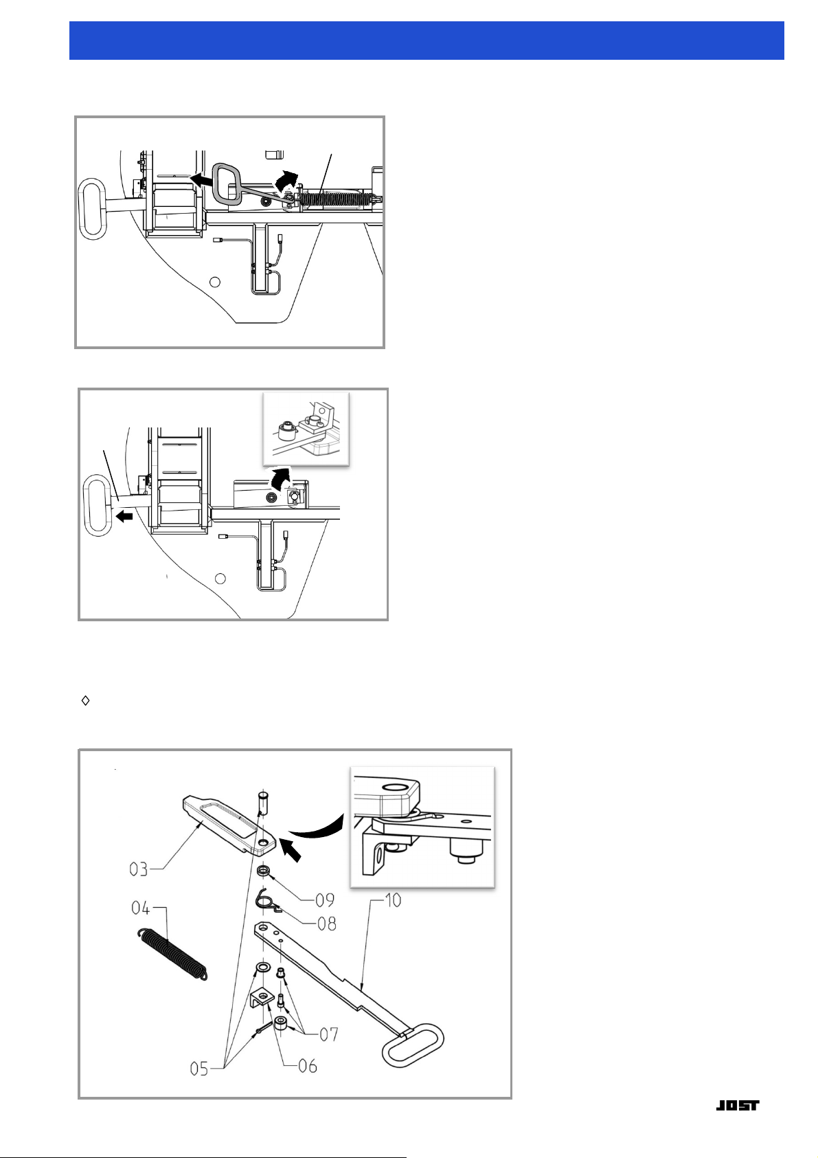
Undo the lock nut on adjusting screw SK 8301-301 and
tighten the screw (max. 30 Nm) to prestress the locking
mechanism. Swing the handle forwards to disengage the
lock. Have a second person on the opposite side of
the fifth
wheel coupling with a crow bar (20 mm in diameter and
approx. 600 mm long) hit the tip of the locking bar
SK 8101-
201 through the hole provided for this purpose in the rib so
as to release the bar. Then rectify the poor maintenance
problem, check the wear parts for signs of damage and
repair them if necessary and reset the locking mechanism.
Fifth wheel cou-
pling does not
stay in its pre-
set position.
Fifth wheel cou-
pling will not
lock.
1.King pin position
is
too high.
2.Skid plate uneven,therefore
the king pin is positioned
incorrectly.
3.King pin is not true to size or
is damaged.
4.Lock jaw
deformed.
5.Poor maintenance.
6.Double tension spring
defective.
7.Lever and/or handle
is
bent.
1.The skid plate should be at the same level or max.
50 mm
lower than the fifth wheel coupling.
2.Change the skid plate. Permitted flatness tolerance
max.
2 mm.
3.Replace the kingpin.
4.ReplacelockjawSK8101-201
5.Open the mechanism and greaseit.
6.Replace double tension springSK8301-210.
7.Replace or straighten the lever SK 8301-214 and
handle
SK8301-213.
Solution
1.The semi-trailer unit is not flat
or is pulling on the coupling.
2.Poor maintenance, damageto
the lock jaw or locking bar or
incorrect lock jaw
adjustment.
1.ReplacelockjawSK8101-201
2.ReplacespringSK2106-01.
3.Open the mechanism.
1.Lock jaw
deformed.
2.Spring defective.
3.Poormaintenance.

5
2 Troubleshooting
Fifth wheel cou-
pling does not
stay in its open
position.
1.
Replace springSK2106-01.
Movement bet-
ween the fifth
wheel coupling
and the trailer
(banging).
1.Spring defective.
1.Bearinghasexcessiveplay.
2.Locking mechanism has
excessiveplay.
1.
Replace bearing bush SK8301-204
if it shows signs of wear.
Tighten the locking screw SK8301-302.
2.
Check the king pin and replace it if it shows signs
of
wear.
If there is still play despite the king pin being the correct size,
adjust the locking mechanism (see 4.13). If this does not pro-
duce the required result, replace the lock jaw SK 8101-201,
wear ring SK8301-223,lockingbarSK8301-209 and
locking
bolt SK8301-304.

6
150 mm
1/2´´
1/2´´
100 mm
1/2´´
SW17
1/2´´
SW19
1/2´´
SW10
SW17
SW17
4-12
6mm
1500gr.
200mm
3 Standard tools and operating media
3.1
Standard tools
3.2
Operating
media
High
pressure
grease
(EP)
with
MoS
2
or
graph
i
te
additive
.

7
!
4 Repair work
Itisessentialthatyouusethetorque values showninthe drawings. Worn,
damaged and tornparts must always be replaced.
Repair welding is not allowed.
►
Repair work is to be completed by trained personnel.
►
Repair work is to be completed with suitable tools
using state of the art methods.
►
The item numbers in the drawings refer to the spare
parts lists in sections
.
►
Instructions for assembly are marked with a diamond
►
The assembly work is to be completed following the
instructions for removal in reverse,
unless described separately.
►
The torque values shown in the drawings are required for the assembly procedure.
►
Clean all the parts thoroughly before assembly.
►
After completing the work, grease the locking mechanism and check that it works.

8
12
!
80
Nm
1/2´´
1/2´´
SW19
1500 gr.
6-12 mm
25
26
1500 gr.
4 Repair work
4.1
Toremove and install bushing
Note
Release the screws and undo them.
12 swivel pin with stop
Drive out the swivel pin with stop.
(12)。
Lifting
hole
The fifth wheel coupling may only be lifted using suitable lifting gear.
When lifting, please pay
attention to safety
T
ake the fifth wheel coupling off the tractor unit
and place it on work bench.
25
Hexagon head screw
26 Retaining sheet

9
1500 gr.
1/2´´
1/2´´
SW19
1500 gr.
6-12 mm
80
Nm
14
25
26
4 Repair work
14 Bushing
25 Hexagon head screw
26 Retaining sheet
Insert
screws and bend over the locking tab.
Drive out the bushing(14
)
Apply a thin coating of grease to the new bearing bushing
(14) and carefully drive it into the pedestal
Apply a thin coating of grease to the inside of the
pedestals before installing the bearing bushes.

10
04
10
4 Repair work
4.2
Toremoveandinstallthelockingmechanism
04 Double tension spring
10 Pull handle
Release the double spring (04).
Remove locking mechanism assembly in turn and pull
the handle out in the direction indicated by the
arrow.
As you install the locking mechanism grease all the
moving parts. Adjust the locking mechanism as
described in
4.6.
03 Lock bar
.
04 Double tension spring
.
05 Bar bolt compl.
06 Fixing loop
.
07 Bolt compl.
08 Spring
.
09 Washer
.
10 Pull handle
.

11
1/2´´
1/2´´
SW1
0
80 Nm
1
7
16
JSK38/04
4 Repair work
4.3
Toremoveandinstallthe wearing ring
17
Socket head bolt
Note
The wearing ring may be adjusted on the vehicle if
it shows signs of wear.
Undo the bolts (17).
16
Wearing ring
Lever out the wearing ring (16) using a tyre lever.

12
02
JSK38/05
27
28
4 Repair work
4.4
To remove and install the lock jaw
Remove the wearing ring (see 4.3).
27
Spring
Release the spring (27).
02
Bolt
Pull out the bolt (02).
During installation tighten the cap screw by hand and then tighten it a further 1.5 to 2 turns.
28
Lock jaw
Remove the lock jaw (28) as shown.
Before installing the lock jaw (28), check the wear on the lock jaw (28) (see 4.7).

4 2
3
1
1/2´´
1/2´´
SW17
SW 17
11
A
4 Repair work
4.5
Toremove andinstallthe latchmechanism
11
Latch mechanism,
complete
.
Undo the screw connection and remove the latch.
4.6
To adjust the locking mechanism
1
3
1 king pin
2 adjust screw
3
locking nut
4
handle
When adjust the locking mechanism,
a trailer with
a new king pin and no forced
steering
must
be used
.
The help of an assistant is recommended.
The adjust steps are as follows:
Un
coupl
e
on flat,
firm
ground
.
U
ndo the locking nut
.
Loosen adjusting screw about 10 turns
.
C
oupl
e the kingpin into the coupling again.
Push or tap on the handle in the direction A to fully close the lock bar.
Tighten the adjusting bolt again until the handle starts to move (let the assistant check)
Then tighten the adjusting screw one and a half
turns,
and secure with the
lock nut (1)
.
Note
If the gap is still too large, the wear ring and the lock jaw must be replaced according to the
maintenance manual.

14
150 mm
150 mm
4 Repair work
4.
7
Wear limit, adjustment and inspection dimensions
(1) check the lock jaw
When the wear limit has been reached, the affected
lock jaw must be replaced.
(2)check the wearing ring
3.5" - 37
- 35 mm
3.5" -
36
-
34.5
mm
When the wear limit has been reached, the
wearing ring must be replaced.

150 mm
3.5" - 114
- 112 mm
3.5" - 89.0
- 86 mm
T≥16mm
4 Repair work
(3)Check the king pin
1
5
When the wear limit is reached replace the 3.5" king pin.
Note
The maximum flatness deviation of the skid plate is
2
mm.
The wear of the king pin shall not be compensated by the adjusting device. The adjusting mechanism is
only used for the clearance adjustment of the fifth
wheel.
(4)
C
heck the coupling plate
Coupling plate wear check
T
he minimum
permitted thickness of the coupling plate is 16mm. The fifth
wheel must be replaces with T
<
16mm.

Item
Description
Serial no./Note
Article number
Quantity
per JSK
0
1
3,5"(90)
SK
8301
-
005
1
02
SK8301
-
307
1
0
3
SK8301
-
209
1
0
4
SK8301
-
210
1
0
5
SK8301
-
006
1
0
6
SK8101
-
206
1
0
7
SK8301
-
007
1
0
8
Spring
SK2405
-
09
1
0
9
Washer
SK8101
-
305
1
10
SK8301
-
213
1
11
SK8301
-
008
1
12
SK8301
-
205
2
13
000.001.148+SK3104-046
2
14
SK8301
-
204
2
15
SK8301
-
224
2
16
SK8301
-
223
1
17
SK2421
-
08
5
18
SK8301
-
301
1
19
SK8301
-
220
2
20
SK8301
-
221
4
21
SK8301
-
222
2
22
SK8301
-
308
10
23
SK8301
-
310
8
24
SK8301
-
309
8
25
SK8301
-
308
-
01
4
5 Spare parts for JSK52DV
1
6
Lock jaw compl.
Pivot
Lock bar
Double tension spring
Bar bolt
Fixing
bracket
Bolt
Comp
ete
.
Comp
lete
.
Com
plete
Compl
ete
.
3,5"(90)
Pull handle
Latch mechanism
Swivel pin with stop
Hexagon head screw + Retaining
plat
Bushing
Pedestal(196mm)
Wearing ring
Socket head cap screw
Adjust screw with hexagon nut
Grease
pi
p
e 1
Grease
pipe 2
Grease pipe 3
Grease
nipple
Grease
pipe joint
90°
grease
pipe joint
Grease
nipple-long

1
7
6 Waste disposal instructions
The mounted parts are valuable raw materials that can be recycled. They can be split into plastics,
rubber and metallic materials. The plastics and rubber material are identified pursuant to VDA
Recommendation 260. All oil and grease is to be cleaned off the parts before their desposal.
Table of contents
Other jost Industrial Equipment manuals