joule ACAPELLA User manual

1
SOLAR SYSTEMS
manual and maintenance
JOULE SOLAR SYSTEMS
operation and maintenance home owner manual


3
SOLAR SYSTEMS
manual and maintenance
Table of Contents:
04 Joule Solar Hot Water Systems
05 Solar Controller Wiring Diagram
06 Panel Types
07 How Your Solar System Works
10 Troubleshooting
13 What Maintenance Is Required
14 Maintenance Sheet

4
Joule Solar Hot Water Systems
All our systems are designed to be fully automatic in operation, require no intervention
by you and are designed to provide many years of trouble free operation. However,
please take a moment to read these notes in conjunction with our commissioning
certicate and leaets for the solar pump station and controller that we provided on
installation (controller supplied will vary dependent on solar collectors installed and
installation type. These documents should be retained for future reference ( a copy of
our commissioning certicate lodged inside the solar pump station housing, providing
all the details that a service engineer would require)

5
SOLAR SYSTEMS
manual and maintenance
DeltaSol®BS/4
© RESOL_12089_deltasol_bs4_v2.monen.indd
|6
910
VBus
S1
S2
S4 / TR
System layout 1
The controller calculates the temperature difference
between collector sensor S1 and store sensor S2. If the
difference is larger than or identical to the adjusted switch-
on temperature difference (DT O), the solar pump will be
operated by relay 1, and the store will be loaded until the
switch-off temperature difference (DT F) or the maximum
store temperature (S MX) is reached.
R1
Arr 1
S3
1.4 Terminal allocation in the different system layouts
Display Channels
Channel Description Terminal Page
INIT x* ODB initialisation active - 18
FLL x* ODB filling time active - 18
STAB x* ODB stabilisation in progress - 18
COL x Temperature collector S1 18
TST x Temperature store S2 18
S3 x Temperature sensor 3 S3 18
TSTT x* Temperature store at the top S3 18
S4 x Temperature sensor 4 S4 18
TR x* Temperature return sensor S4 18
n % x Pump speed R1 R1 19
hP x Operating hours R1 R1 19
hP1 x* Operating hours R1 (if OBST is activated) R1 19
hP2 x* Operating hours R2 (if OBST is activated) R2 19
kWh x* Heat quantity kWh - 19
MWh x* Heat quantity MWh - 19
TIME x Time - 16
Sensors S3 and S4 can optionally be connected for mea-
surement purposes. S3 can optionally be used as reference
sensor for the store emergency shutdown option (OSEM).
If heat quantity measurement (OHQM) is activated, sensor
S4 has to be connected as return sensor.
If the drainback option (ODB) is activated, relay 2 can be
used to operate a booster pump by activating the booster
function (OBST).
S1
S3
S2
S4/TR
R1 R2
exemplary
Drainback system layout
(with booster pump)
DISPLAY CHANNELS
Channel Description Terminal
INIT x* ODB initialisation active -
FLL x* ODB lling time active -
STAB x* ODB stabilisation in progress -
COL x Temperature collector S1
TST x Temperature store S2
S3 x Temperature sensor 3 S3
TSTT x* Temperature store at the top S3
S4 x Temperature sensor 4 S4
TR x* Temperature return sensor S4
n % x Pump speed R1 R1
hP x Operating hours R1 R1
hP1 x* Operating hours R1 (if OBST is activated) R1
hP2 x* Operating hours R2 (if OBST is activated) R2
kWh x* Heat quantity kWh -
MWh x* Heat quantity MWh -
TIME x Time -
DeltaSol®BS/4
© RESOL_12089_deltasol_bs4_v2.monen.indd
|6
910
VBus
S1
S2
S4 / TR
System layout 1
The controller calculates the temperature difference
between collector sensor S1 and store sensor S2. If the
difference is larger than or identical to the adjusted switch-
on temperature difference (DT O), the solar pump will be
operated by relay 1, and the store will be loaded until the
switch-off temperature difference (DT F) or the maximum
store temperature (S MX) is reached.
R1
Arr 1
S3
1.4 Terminal allocation in the different system layouts
Display Channels
Channel Description Terminal Page
INIT x* ODB initialisation active - 18
FLL x* ODB filling time active - 18
STAB x* ODB stabilisation in progress - 18
COL x Temperature collector S1 18
TST x Temperature store S2 18
S3 x Temperature sensor 3 S3 18
TSTT x* Temperature store at the top S3 18
S4 x Temperature sensor 4 S4 18
TR x* Temperature return sensor S4 18
n % x Pump speed R1 R1 19
hP x Operating hours R1 R1 19
hP1 x* Operating hours R1 (if OBST is activated) R1 19
hP2 x* Operating hours R2 (if OBST is activated) R2 19
kWh x* Heat quantity kWh - 19
MWh x* Heat quantity MWh - 19
TIME x Time - 16
Sensors S3 and S4 can optionally be connected for mea-
surement purposes. S3 can optionally be used as reference
sensor for the store emergency shutdown option (OSEM).
If heat quantity measurement (OHQM) is activated, sensor
S4 has to be connected as return sensor.
If the drainback option (ODB) is activated, relay 2 can be
used to operate a booster pump by activating the booster
function (OBST).
S1
S3
S2
S4/TR
R1 R2
exemplary
Drainback system layout
(with booster pump)
Solar Controller Wiring Diagram

6
Panel Types
The type of control system installed in your property depends on the panel type sup-
plied with your system. The solar system installed in your home features either the
Joule Navitas on-roof or in-roof solar panels, Joule VisSolis in-roof solar panels or
Joule Acapella high eciency vacuum tube solar panels.
Joule Navitas On-roof
Joule Acapella
Joule Navitas In-roof
Joule VisSolis In-roof

7
SOLAR SYSTEMS
manual and maintenance
How Your Solar System Works
The Joule solar system installed is designed to heat your hot water cylinder using energy
from daylight and air temperature. The solar system works by taking the heated uid in
the solar collector and pumping it through the pipe work into the coil in your hot water
cylinder. This hot uid transfers its heat into your stored water in your hot water cylinder.
For this to work the temperature of the uid in your solar collector must be warmer than
the temperature of the water in your cylinder that surrounds the coil used by the solar. This
coil is normally located at the bottom of you cylinder as this is the pre-heat part of your hot
water cylinder. (See notes on how solar heats the hot water cylinder)
Phase 2
When hot water is used, hot water level rises and is replaced by
cold water.
The level of hot water rises in the cylinder thus reducing the amount
of hot water in the cylinder. The cold water enters the cylinder from
the base replenishing the used hot water.
Phase 3
When there is a solar gain it heats cold water at the bottom of the
cylinder, thus reducing the load on the boiler.
Solar gain enters the cylinder through the bottom coil. This pre-
heats the cold water before it rises up to the boiler coil. The greater
the level of solar gain, the more the cold water is preheated, the
less the boiler must heat.
Phase 1
When boiler operates and there is no solar gain.
Boiler heats up top half of cylinder from the point the boiler coil
starts in the middle of cylinder. Because hot water rises only, when
the boiler is operating and no solar gain is present only the top half
of the cylinder can be heated.
Joule Navitas On-roof
Joule Acapella
Joule Navitas In-roof
Joule VisSolis In-roof

8
How Your Solar System Works
The solar system is not designed to supplement your heating system. (unless expressly
designed with that purpose but as standard it is to heat hot water only). The solar system
will only circulate hot water from the collector on the roof to your hot water cylinder when
the roof uid temperature is 7°C warmer than the water in your hot water cylinder. The
uid in your solar collector must be above 20°C before it looks at the temperature dieren-
tial between the collector and the cylinder. If the cylinder is fully heated to 60°C (maximum
store temperature as set by default on your solar controller) than the solar controller will
shut down the solar system regardless of what temperature is available from the solar
panels on the roof. It does this because the hot water cylinder has been fully heated and
required no further heat.
What happens when your hot water cylinder is fully heated and it is
still sunny outside
Your solar system is designed to deal with this situation. Your solar
controller is programmed to shut o your solar system when you’re
hot water cylinder has been fully heated. This ensures that the water
in your cylinder never over heats and risks very hot water coming
out of your taps. Your solar controller is programmed to shut down
the solar system when you’re hot water cylinder reaches a tem-
perature of 60®C at the bottom of the cylinder. This temperature is
chosen because it is a safe temperature to store hot water both by
not being too hot and protecting people from scalding and also not
too cold to reduce the risk of legionnaires.
When the cylinder is fully heated the solar controller shuts down
the solar system. This will generally happen after a number of
sunshine hours and the initial energy has heated the cylinder
completely. The temperature of the uid in the solar collector will
begin to heat up signicantly. This will lead to a build up in pres-
sure in the solar system. This is where the expansion vessel of
your solar system begins to work. While the heated uid will only
be located on the roof the pressure will pass back down the pipe
work into the solar expansion vessel. The membrane will ex to
allow for the increase in pressure. This process is a full safe pro-
cess and how the system is designed to work.
If for some reason the system has too much pressure and a fault
occurs the safety valve on your solar pump station will open and
allow a small amount of uid to discharge into your solar dis-
charge vessel. If this happens please notify your local service
engineer.

9
SOLAR SYSTEMS
manual and maintenance
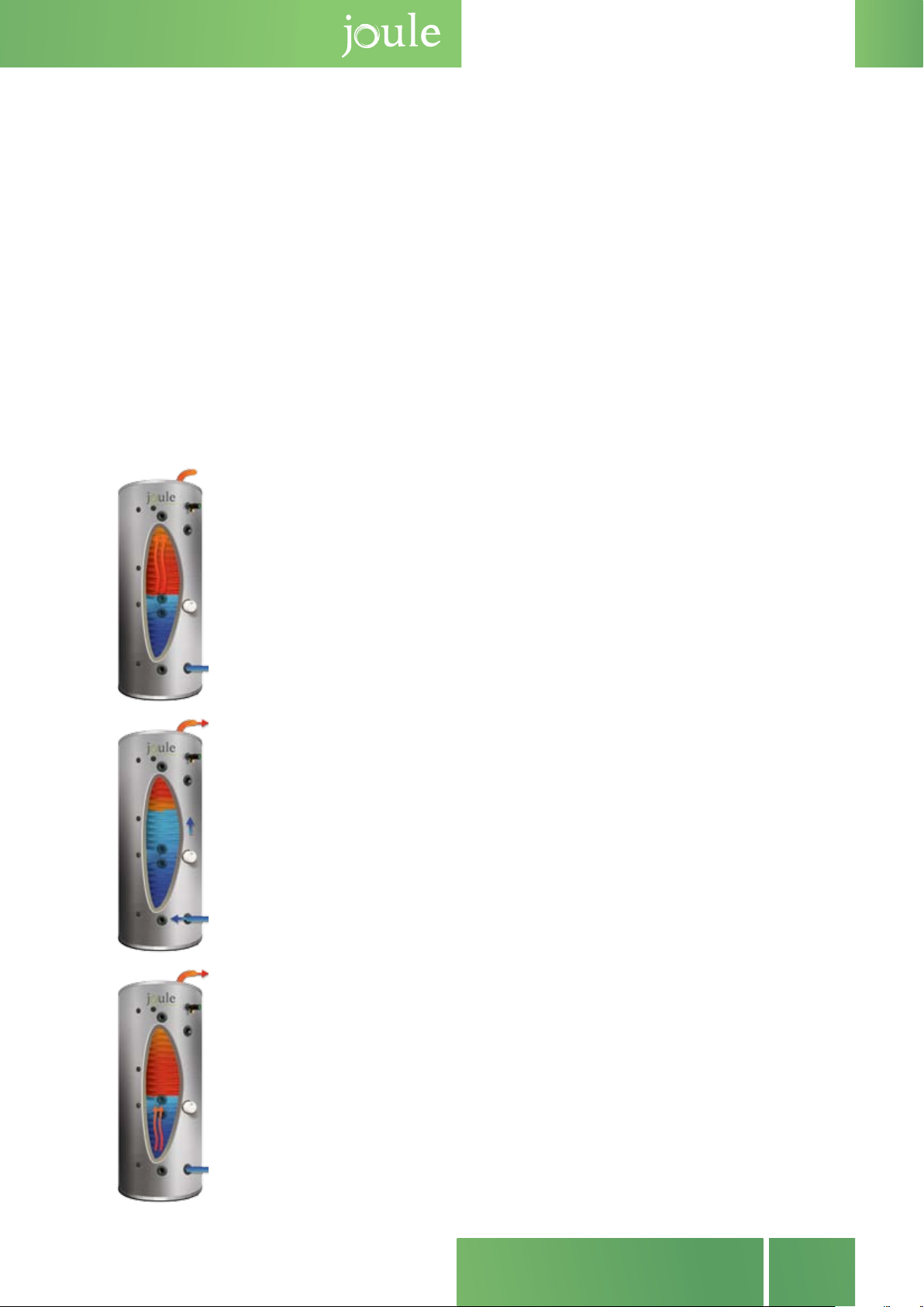
What happens when you go on holidays
When you go on holidays or leave your house for more than a couple of days then you are
not using any hot water out of your hot water cylinder. This means that the solar system
heats your cylinder on day 1 and then on day 2 it has no water left to heat because the
cylinder was heated the previous day and no water has been taken out of the hot water
cylinder. To change any options including setting up the controller for going on holidays
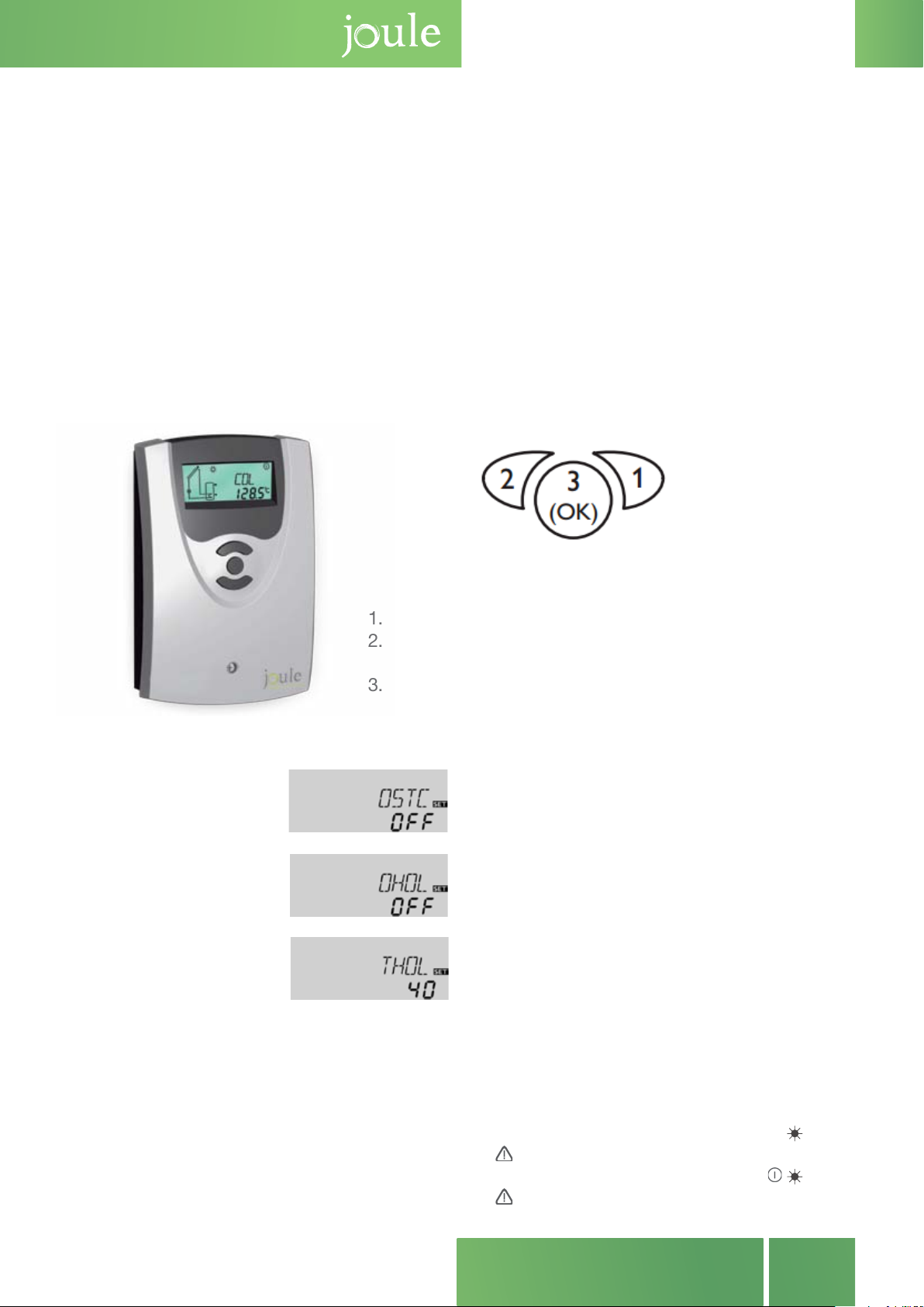
you must rst enter the service menu of the controller. To do this, follow these steps.
1. Tap button 1 until you reach the TIME screen
2. Press and hold button 1 until the screen moves.
(3 seconds to move).
3. Tap button 1 until you reach the desired screen.
The three buttons of the BS/4 controller
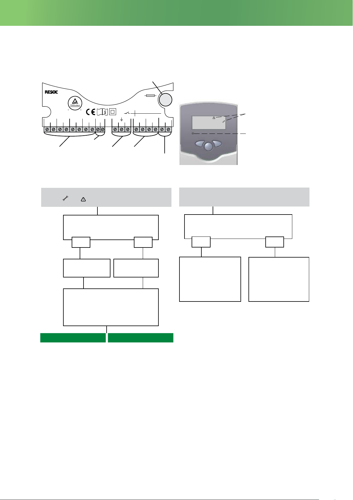
DeltaSol®BS/4
© RESOL_12089_deltasol_bs4_v2.monen.indd
23 |
CMN:
Collector minimum temp.
Adjustment range:
10 ... 90 °C [50...190 °F]
in steps of 0.5 K [1 °Ra]
Factory setting:
10 °C [50 °F]
Collector minimum limitation option
OCN:
Collector minimum limitation
Adjustment range: OFF / ON
Factory setting: OFF
If the collector minimum limitation option is activated,
the pump (R1) is only switched on if the adjustable
collector minimum temperature is exceeded.The minimum
temperature prevents the pump from being switched on too
often at low collector temperatures. A fixed hysteresis of
5 K [10 °Ra] is set for this function
If the collector minimum limitation is active, (flashing) is
shown on the display.
Antifreeze option
OCF:
Antifreeze function
Adjustment range: OFF / ON
Factory setting: OFF
The antifreeze function activates the loading circuit between
the collector and the store when the temperature falls below
the adjusted antifreeze temperature. This will protect the
fluid against freezing or coagulating.If the adjusted antifreeze
temperature is exceeded by 1 K [2 °Ra], the loading circuit
will be deactivated.
When the antifreeze function is activated, is shown on
the display. If the antifreeze function is active, and
(flashing) are shown on the display.
Note:
Since this function uses the limited heat quantity
of the store, the antifreeze function should be
used in regions with few days of temperatures
around the freezing point.
The antifreeze function will be suppressed if the
store temperature falls below 5 °C [40 °F] in
order to protect the store from frost damage.
CFR:
Antifreeze temperature
Adjustment range:
-40.0 ... +10.0 °C
[-40.0 ... +50.0 °F]
in steps of 0.5 K [1 °Ra]
Factory setting:
4.0 °C [40.0 °F]
Store cooling function
When the store cooling function is activated, the controller
aims to cool down the store during the night in order to
prepare it for solar loading on the following day.
If the adjusted maximum store temperature S MX is
exceeded and the collector temperature falls below the
store temperature, the system will be reactivated in order
to cool down the store. Cooling will continue until the store
temperature has fallen below the adjusted maximum store
temperature S MX again. A fixed hysteresis of 2 K [4 °Ra]
is set for this function.
Reference threshold temperature differences for the store
cooling function are DT O and DT F.
If no DHW consumption is expected for a longer period of
time, the additional holiday cooling option OHOL can be
activated in order to extend the store cooling function.The
adjustable temperature THOL then replaces the maximum
store temperature S MX as a switch-off temperature for the
store cooling function.
When the holiday cooling function is activated,and
(flashing) are shown on the display.
While the holiday cooling function is active, ,and
(flashing) are shown on the display.
OSTC:
Store cooling option
Adjustment range: OFF /ON
Factory setting: OFF
THOL:
Holiday cooling temperature
Adjustment range:
20 ... 80 °C [70 ... 175 °F]
in steps of 1 K [1 °Ra]
Factory setting:
40 °C [110 °F]
OHOL:
Holiday cooling option
Adjustment range: OFF /ON
Factory setting: OFF
Note:
If OSTC or OCF is active,the collector minimum
function will be overridden. In that case, the
collector temperature may fall below CMN.
When the store cooling function is activated, the
controller aims to cool down the store during the
night in order to prepare it for solar loading on the
following day.
If the adjusted maximum store temperature S MX
is exceeded and the collector temperature falls
below the store temperature, the system will be re-
activated in order to cool down the store. Cooling
will continue until the store temperature has fallen
below the adjusted maximum sture temperature S
MX again. A xed hysteresis of 2K [4 °Ra] is set for
this function.
Reference treshold temperature dierences for the
store cooling function are DT O and DT F.
If no DHW consumption is expected for a longer
period of time, the additional holiday cooling option
OHOL can be activated in order to extend the store
cooling function. The adjustable temperature THOL
then replaces the maximum store temperature S
MX as a switch-o temperature for the store cool-
ing function.
When the holiday cooling function is activated,
DeltaSol®BS/4
© RESOL_12089_deltasol_bs4_v2.monen.indd
23 |
CMN:
Collector minimum temp.
Adjustment range:
10 ... 90 °C [50...190 °F]
in steps of 0.5 K [1 °Ra]
Factory setting:
10 °C [50 °F]
Collector minimum limitation option
OCN:
Collector minimum limitation
Adjustment range: OFF / ON
Factory setting: OFF
If the collector minimum limitation option is activated,
the pump (R1) is only switched on if the adjustable
collector minimum temperature is exceeded.The minimum
temperature prevents the pump from being switched on too
often at low collector temperatures. A fixed hysteresis of
5 K [10 °Ra] is set for this function
If the collector minimum limitation is active, (flashing) is
shown on the display.
Antifreeze option
OCF:
Antifreeze function
Adjustment range: OFF / ON
Factory setting: OFF
The antifreeze function activates the loading circuit between
the collector and the store when the temperature falls below
the adjusted antifreeze temperature. This will protect the
fluid against freezing or coagulating.If the adjusted antifreeze
temperature is exceeded by 1 K [2 °Ra], the loading circuit
will be deactivated.
When the antifreeze function is activated, is shown on
the display. If the antifreeze function is active, and
(flashing) are shown on the display.
Note:
Since this function uses the limited heat quantity
of the store, the antifreeze function should be
used in regions with few days of temperatures
around the freezing point.
The antifreeze function will be suppressed if the
store temperature falls below 5 °C [40 °F] in
order to protect the store from frost damage.
CFR:
Antifreeze temperature
Adjustment range:
-40.0 ... +10.0 °C
[-40.0 ... +50.0 °F]
in steps of 0.5 K [1 °Ra]
Factory setting:
4.0 °C [40.0 °F]
Store cooling function When the store cooling function is activated, the controller
aims to cool down the store during the night in order to
prepare it for solar loading on the following day.
If the adjusted maximum store temperature S MX is
exceeded and the collector temperature falls below the
store temperature, the system will be reactivated in order
to cool down the store. Cooling will continue until the store
temperature has fallen below the adjusted maximum store
temperature S MX again. A fixed hysteresis of 2 K [4 °Ra]
is set for this function.
Reference threshold temperature differences for the store
cooling function are DT O and DT F.
If no DHW consumption is expected for a longer period of
time, the additional holiday cooling option OHOL can be
activated in order to extend the store cooling function.The
adjustable temperature THOL then replaces the maximum
store temperature S MX as a switch-off temperature for the
store cooling function.
When the holiday cooling function is activated,and
(flashing) are shown on the display.
While the holiday cooling function is active, ,and
(flashing) are shown on the display.
OSTC:
Store cooling option
Adjustment range: OFF /ON
Factory setting: OFF
THOL:
Holiday cooling temperature
Adjustment range:
20 ... 80 °C [70 ... 175 °F]
in steps of 1 K [1 °Ra]
Factory setting:
40 °C [110 °F]
OHOL:
Holiday cooling option
Adjustment range: OFF /ON
Factory setting: OFF
Note:
If OSTC or OCF is active,the collector minimum
function will be overridden. In that case, the
collector temperature may fall below CMN.
and
DeltaSol®BS/4
© RESOL_12089_deltasol_bs4_v2.monen.indd
23 |
CMN:
Collector minimum temp.
Adjustment range:
10 ... 90 °C [50...190 °F]
in steps of 0.5 K [1 °Ra]
Factory setting:
10 °C [50 °F]
Collector minimum limitation option
OCN:
Collector minimum limitation
Adjustment range: OFF / ON
Factory setting: OFF
If the collector minimum limitation option is activated,
the pump (R1) is only switched on if the adjustable
collector minimum temperature is exceeded.The minimum
temperature prevents the pump from being switched on too
often at low collector temperatures. A fixed hysteresis of
5 K [10 °Ra] is set for this function
If the collector minimum limitation is active, (flashing) is
shown on the display.
Antifreeze option
OCF:
Antifreeze function
Adjustment range: OFF / ON
Factory setting: OFF
The antifreeze function activates the loading circuit between
the collector and the store when the temperature falls below
the adjusted antifreeze temperature. This will protect the
fluid against freezing or coagulating.If the adjusted antifreeze
temperature is exceeded by 1 K [2 °Ra], the loading circuit
will be deactivated.
When the antifreeze function is activated, is shown on
the display. If the antifreeze function is active, and
(flashing) are shown on the display.
Note:
Since this function uses the limited heat quantity
of the store, the antifreeze function should be
used in regions with few days of temperatures
around the freezing point.
The antifreeze function will be suppressed if the
store temperature falls below 5 °C [40 °F] in
order to protect the store from frost damage.
CFR:
Antifreeze temperature
Adjustment range:
-40.0 ... +10.0 °C
[-40.0 ... +50.0 °F]
in steps of 0.5 K [1 °Ra]
Factory setting:
4.0 °C [40.0 °F]
Store cooling function When the store cooling function is activated, the controller
aims to cool down the store during the night in order to
prepare it for solar loading on the following day.
If the adjusted maximum store temperature S MX is
exceeded and the collector temperature falls below the
store temperature, the system will be reactivated in order
to cool down the store. Cooling will continue until the store
temperature has fallen below the adjusted maximum store
temperature S MX again. A fixed hysteresis of 2 K [4 °Ra]
is set for this function.
Reference threshold temperature differences for the store
cooling function are DT O and DT F.
If no DHW consumption is expected for a longer period of
time, the additional holiday cooling option OHOL can be
activated in order to extend the store cooling function.The
adjustable temperature THOL then replaces the maximum
store temperature S MX as a switch-off temperature for the
store cooling function.
When the holiday cooling function is activated,and
(flashing) are shown on the display.
While the holiday cooling function is active, ,and
(flashing) are shown on the display.
OSTC:
Store cooling option
Adjustment range: OFF /ON
Factory setting: OFF
THOL:
Holiday cooling temperature
Adjustment range:
20 ... 80 °C [70 ... 175 °F]
in steps of 1 K [1 °Ra]
Factory setting:
40 °C [110 °F]
OHOL:
Holiday cooling option
Adjustment range: OFF /ON
Factory setting: OFF
Note:
If OSTC or OCF is active,the collector minimum
function will be overridden. In that case, the
collector temperature may fall below CMN.
(ashing) are shown on the display.
While the holiday cooling function is active,
DeltaSol®BS/4
© RESOL_12089_deltasol_bs4_v2.monen.indd
23 |
CMN:
Collector minimum temp.
Adjustment range:
10 ... 90 °C [50...190 °F]
in steps of 0.5 K [1 °Ra]
Factory setting:
10 °C [50 °F]
Collector minimum limitation option
OCN:
Collector minimum limitation
Adjustment range: OFF / ON
Factory setting: OFF
If the collector minimum limitation option is activated,
the pump (R1) is only switched on if the adjustable
collector minimum temperature is exceeded.The minimum
temperature prevents the pump from being switched on too
often at low collector temperatures. A fixed hysteresis of
5 K [10 °Ra] is set for this function
If the collector minimum limitation is active, (flashing) is
shown on the display.
Antifreeze option
OCF:
Antifreeze function
Adjustment range: OFF / ON
Factory setting: OFF
The antifreeze function activates the loading circuit between
the collector and the store when the temperature falls below
the adjusted antifreeze temperature. This will protect the
fluid against freezing or coagulating.If the adjusted antifreeze
temperature is exceeded by 1 K [2 °Ra], the loading circuit
will be deactivated.
When the antifreeze function is activated, is shown on
the display. If the antifreeze function is active, and
(flashing) are shown on the display.
Note:
Since this function uses the limited heat quantity
of the store, the antifreeze function should be
used in regions with few days of temperatures
around the freezing point.
The antifreeze function will be suppressed if the
store temperature falls below 5 °C [40 °F] in
order to protect the store from frost damage.
CFR:
Antifreeze temperature
Adjustment range:
-40.0 ... +10.0 °C
[-40.0 ... +50.0 °F]
in steps of 0.5 K [1 °Ra]
Factory setting:
4.0 °C [40.0 °F]
Store cooling function When the store cooling function is activated, the controller
aims to cool down the store during the night in order to
prepare it for solar loading on the following day.
If the adjusted maximum store temperature S MX is
exceeded and the collector temperature falls below the
store temperature, the system will be reactivated in order
to cool down the store. Cooling will continue until the store
temperature has fallen below the adjusted maximum store
temperature S MX again. A fixed hysteresis of 2 K [4 °Ra]
is set for this function.
Reference threshold temperature differences for the store
cooling function are DT O and DT F.
If no DHW consumption is expected for a longer period of
time, the additional holiday cooling option OHOL can be
activated in order to extend the store cooling function.The
adjustable temperature THOL then replaces the maximum
store temperature S MX as a switch-off temperature for the
store cooling function.
When the holiday cooling function is activated,and
(flashing) are shown on the display.
While the holiday cooling function is active, ,and
(flashing) are shown on the display.
OSTC:
Store cooling option
Adjustment range: OFF /ON
Factory setting: OFF
THOL:
Holiday cooling temperature
Adjustment range:
20 ... 80 °C [70 ... 175 °F]
in steps of 1 K [1 °Ra]
Factory setting:
40 °C [110 °F]
OHOL:
Holiday cooling option
Adjustment range: OFF /ON
Factory setting: OFF
Note:
If OSTC or OCF is active,the collector minimum
function will be overridden. In that case, the
collector temperature may fall below CMN.
and
DeltaSol®BS/4
© RESOL_12089_deltasol_bs4_v2.monen.indd
23 |
CMN:
Collector minimum temp.
Adjustment range:
10 ... 90 °C [50...190 °F]
in steps of 0.5 K [1 °Ra]
Factory setting:
10 °C [50 °F]
Collector minimum limitation option
OCN:
Collector minimum limitation
Adjustment range: OFF / ON
Factory setting: OFF
If the collector minimum limitation option is activated,
the pump (R1) is only switched on if the adjustable
collector minimum temperature is exceeded.The minimum
temperature prevents the pump from being switched on too
often at low collector temperatures. A fixed hysteresis of
5 K [10 °Ra] is set for this function
If the collector minimum limitation is active, (flashing) is
shown on the display.
Antifreeze option
OCF:
Antifreeze function
Adjustment range: OFF / ON
Factory setting: OFF
The antifreeze function activates the loading circuit between
the collector and the store when the temperature falls below
the adjusted antifreeze temperature. This will protect the
fluid against freezing or coagulating.If the adjusted antifreeze
temperature is exceeded by 1 K [2 °Ra], the loading circuit
will be deactivated.
When the antifreeze function is activated, is shown on
the display. If the antifreeze function is active, and
(flashing) are shown on the display.
Note:
Since this function uses the limited heat quantity
of the store, the antifreeze function should be
used in regions with few days of temperatures
around the freezing point.
The antifreeze function will be suppressed if the
store temperature falls below 5 °C [40 °F] in
order to protect the store from frost damage.
CFR:
Antifreeze temperature
Adjustment range:
-40.0 ... +10.0 °C
[-40.0 ... +50.0 °F]
in steps of 0.5 K [1 °Ra]
Factory setting:
4.0 °C [40.0 °F]
Store cooling function When the store cooling function is activated, the controller
aims to cool down the store during the night in order to
prepare it for solar loading on the following day.
If the adjusted maximum store temperature S MX is
exceeded and the collector temperature falls below the
store temperature, the system will be reactivated in order
to cool down the store. Cooling will continue until the store
temperature has fallen below the adjusted maximum store
temperature S MX again. A fixed hysteresis of 2 K [4 °Ra]
is set for this function.
Reference threshold temperature differences for the store
cooling function are DT O and DT F.
If no DHW consumption is expected for a longer period of
time, the additional holiday cooling option OHOL can be
activated in order to extend the store cooling function.The
adjustable temperature THOL then replaces the maximum
store temperature S MX as a switch-off temperature for the
store cooling function.
When the holiday cooling function is activated,and
(flashing) are shown on the display.
While the holiday cooling function is active, ,and
(flashing) are shown on the display.
OSTC:
Store cooling option
Adjustment range: OFF /ON
Factory setting: OFF
THOL:
Holiday cooling temperature
Adjustment range:
20 ... 80 °C [70 ... 175 °F]
in steps of 1 K [1 °Ra]
Factory setting:
40 °C [110 °F]
OHOL:
Holiday cooling option
Adjustment range: OFF /ON
Factory setting: OFF
Note:
If OSTC or OCF is active,the collector minimum
function will be overridden. In that case, the
collector temperature may fall below CMN.
(ashing) are shown on the display.

Troubleshooting
10
DeltaSol®BS/4
© RESOL_12089_deltasol_bs4_v2.monen.indd
27 |
5. Troubleshooting
Operating control lamp
Warning symbols
Operating control lamp flashes red. On the display the
symbols and appear.
VBus®terminals
DE-45527 Hattingen
DeltaSol BS/4 V2
12
S1 S2 S3
3456
LNR1NR2N
201918171615
S4
78 141312
1 (1)A100 ... 240V~
1 (1)A100 ... 240V~
R1
R2
T4A
VBus
910
CU 72091163 01
100 ... 240V~
50-60 Hz
Temp. Sensor Pt1000
IP 20
Made in Germany
power supply
terminals
fuse
load terminalssensor terminals ground
terminals
In the case of an error, a message is shown on the display
of the controller:
Sensor defect. An error code instead of
a temperature is displayed in the sensor
display channel.
- 88.8888.8
Cable broken.
Check cable.
Short circuit.
Check cable.
Disconnected Pt1000 temperature sen-
sors can be checked with an ohmmeter. In
the following table, the resistance values
with the corresponding temperatures are
shown.
Operating control lamp off.
Check the power supply. Is it disconnected?
no
The fuse of the controller
could be blown. It can be
replaced after the front
cover has been removed
(spare fuse is enclosed in
the accessory bag).
yes
Check the supply line and
reconnect it.
°C °F Ω °C °F Ω
-10 14 961 55 131 1213
-5 23 980 60 140 1232
0 32 1000 65 149 1252
5 41 1019 70 158 1271
10 50 1039 75 167 1290
15 59 1058 80 176 1309
20 68 1078 85 185 1328
25 77 1097 90 194 1347
30 86 1117 95 203 1366
35 95 1136 100 212 1385
40 104 1155 105 221 1404
45 113 1175 110 230 1423
50 122 1194 115 239 1442
Resistance values of the Pt1000 sensors
°C °F Ω
-10 14 961
-5 23 980
032 1000
5 41 1019
10 50 1039
15 59 1058
20 68 1078
25 77 1097
30 86 1117
35 95 1136
40 104 1155
45 113 1175
50 122 1194
°C °F Ω
55 131 1213
60 140 1232
65 149 1252
70 158 1271
75 167 1290
80 176 1309
85 185 1328
90 194 1347
95 203 1366
100 212 1385
105 221 1404
110 230 1423
115 239 1442

11
SOLAR SYSTEMS
manual and maintenance
DeltaSol®BS/4
© RESOL_12089_deltasol_bs4_v2.monen.indd
|28
5.1 Various
Pump starts for a short moment, switches off, switches
on again, etc.
Temperature difference
at the controller too
small?
no yes
Wrong position of collec-
tor sensors?
yes
Change ∆Ton and ∆Toff
correspondingly. Problem
solved?
Mount the collector sen-
sor at solar flow (warmest
collector output); use sen-
sor well of the respective
collector.
Pump starts up very late The temperature difference between store and collector
increases enormously during operation; the collector cir-
cuit cannot dissipate the heat.
Collector circuit pump
defective?
no yes
Heat exchanger calcified?
yes
Check / replace it
Decalcify it
no
Heat exchanger blocked?
yesno Clean it
Heat exchanger too
small?
yes Replace with correctly
sized one.
no
Plausibility control of
the option tube collec-
tor special function
Change ∆Ton and ∆Toff
correspondingly.
Switch-on temperature
difference Ton to large?
no yes
Non-ideal position of the coll-
ector sensor (e.g. flatscrew
sensor instead of sensor in
sensor wells)?
no
Pump is overheated, but no heat transfer from the
collector to the store, flow and return have the same
temperature; perhaps also air / gas bubbles in the lines.
Air in the system; increase
the system pressure to at
least static primary pres-
sure plus 7. 25 psi (0.5 bar);
if necessary continue to
increase pressure; switch
the pump off and on for a
short time.
Air in the system?
no yes
Is the collector circuit
blocked at the dirt trap?
yes
Clean the dirt trap
Activate tube collector
function if necessary.
yes
o.k.
yes
o.k.

12
DeltaSol®BS/4
© RESOL_12089_deltasol_bs4_v2.monen.indd
29 |
Stores cool down at night
Collector circuit pump
runs during the night?
no yes
Check controller:
Manual operation active?
Tube collector function
active? Store cooling
or antifreeze function
active?
Collector temperature is
at night higher than the
outdoor temperature
no yes
Check the check valve in
the flow and the return
pipe with regard to the
functional efficiency.
Sufficient store insula-
tion?
yes no Increase insulation.
Insulation close enough
to the store?
yes no Replace insulation or in-
crease it.
Are the store connec-
tions insulated?
yes no Insulate the connections.
Warm water outflow
upwards?
no yes
Change connection and
let the water flow hori-
zontally or through a si-
phon (downwards); less
store losses now ?
Does the warm water
circulation run for a very
long time?
no yes
Use the circulation pump
with timer and switch-off
thermostat (energy effici-
ent circulation).
The solar circuit pump does not work, although the coll-
ector is considerably warmer than the store.
Is the control lamp (LED)
illuminated?
yes no
Does the pump start up
in manual operation?
yes
There is no current; check
fuses / replace them and
check power supply.
The adjusted temperature
difference for starting the
pump is to high; choose a
value which makes more
sense.
no
Is the pump current
enabled by the control-
ler?
yes
Is the pump stuck?
Turn the pump shaft using
a screwdriver; now pas-
sable?
Pump is defective - re-
place it
Are the controller fuses
o.k. ?
Controller might be defec-
tive - replace it or contact
the distributor.
no
yes
no
no yes
Replace fuses.
Circulation pump and
blocking valve should be
switched off for one night;
less store losses?
yes no
Check whether the
pumps of the afterheating
circuit run at night; check
whether the non-return
valve is defective; problem
solved ?
no
no yes
o.k.
Control the non-return
valve in warm water cir-
culation - o.k.
yes no
Further pumps which are
connected to the solar
store must also be che-
cked.
The thermosiphoning in
the circulation line is too
strong; insert a stronger
valve in the non-return val-
ve or an electrical 2-port
valve behind the circulati-
on pump; the 2-port valve
is open when the pump is
activated, otherwise it is
closed; connect pump and
2-port valve electrically in
parallel; activate the circu-
lation again
Clean or replace it
a
a b
b
yes
o.k.

13
SOLAR SYSTEMS
manual and maintenance
What Maintenance Is Required
The Joule solar system should be maintained annually by a competent person.
1. for correct operation of safety measures (over pressure and temperature)
2. continued system and expansion vessel pressurisation
3. any faults recorded on the solar controller
4. antifreeze acidity (to be checked with a refractomoter)
Every 3 years the transfer uid within the system should be changed if it has not been
changed during one of annual services to fresh transfer uid of the same type.
The power supply to the solar controller should not be switched o for any prolonged
period of time.
- Notify plumber if system pressure is 0.
- The controller should be on at all times and not turned off except for
maintainence.
Warranty Denition
All Joule products come with a manufacturers guarantee. Your solar system comes
with a 10 year guarantee on the collector and 2 year guarantee on the solar com-
ponents. This guarantee covers all manufacturing defects. This guarantee does not
cover failure or damage due to incorrect installation as per installation documents and
current plumbing best practices. If you notice an issue with your solar system call your
installer and ask them to have a look at the system. If the issue is a product warranty
issue your installer will contact Joule to arrange for the issue to be resolved.

14
Date of Service Service Engineer Name Engineer Number Issues Noted
Maintenance Sheet

15
SOLAR SYSTEMS
manual and maintenance

Kylemore Park West, Ballyfermot, Dublin 10
+353 (1) 623 7080
+353 (1) 626 9337
www.joule.ie
Unit 17C&D Power Road, Plantation Bus. Pk.
Bromborough, Wirral, CH62 3RN
+44 (0) 1513 551 094
+44 (0) 1513 568 336
www.jouleuk.co.uk
23-200 Kraśnik, ul. Towarowa 34.
+48 (0) 128811171
+48 (0) 814709046
www.joule-pl.pl
JOULE IE JOULE UK JOULE PL
mail
tel
fax
eml
web
mail
tel
fax
eml
web
mail
tel
fax
eml
web
Other manuals for ACAPELLA
2
This manual suits for next models
3
Table of contents
Other joule Solar Panel manuals