Joy Sport Z-11 Special User manual

OWNER’S MANUAL
Joy Sport
Z-11 Special

2
TABLE OF CONTENTS
*SAFETY & MAINTENANCE INSTRUCTION 3
*FEATURES 4
*Exploded Drawing of Home Spinner 5
*Bill of Material for Home Spinner 6
*ASSEMBLY INSTRUCTION
Parts List 8
Assembly Steps 10
* OPERATION
Leveling the Bike 12
Resistance Adjustment 12
Seat Adjustment 12
Handlebar Adjustment 13
Pedal Strap Adjustment 13
Workout 13
Dismounting the Bike 13
Moving the Bike 13

3
SAFETY & MAINTENANCE INSTRUCTION
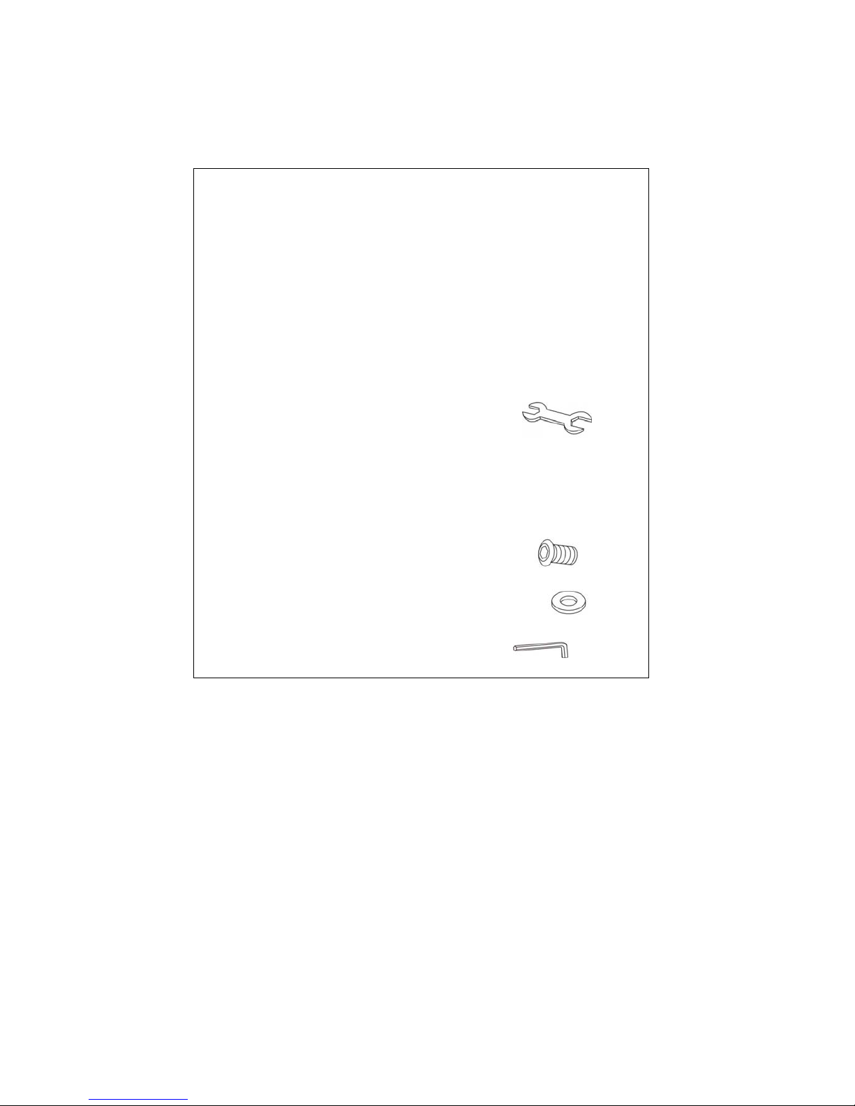
1. Once fully assembled, please check that all hardware parts such as bolts,
nuts and washers are positioned and secured firmly.
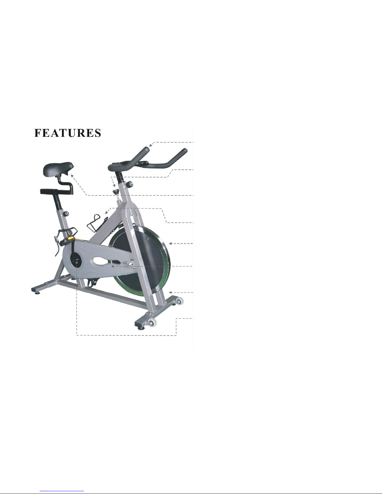
2. Please check regularly that the safety chain guard that protects the moving
parts of the machine is secured and in good order.
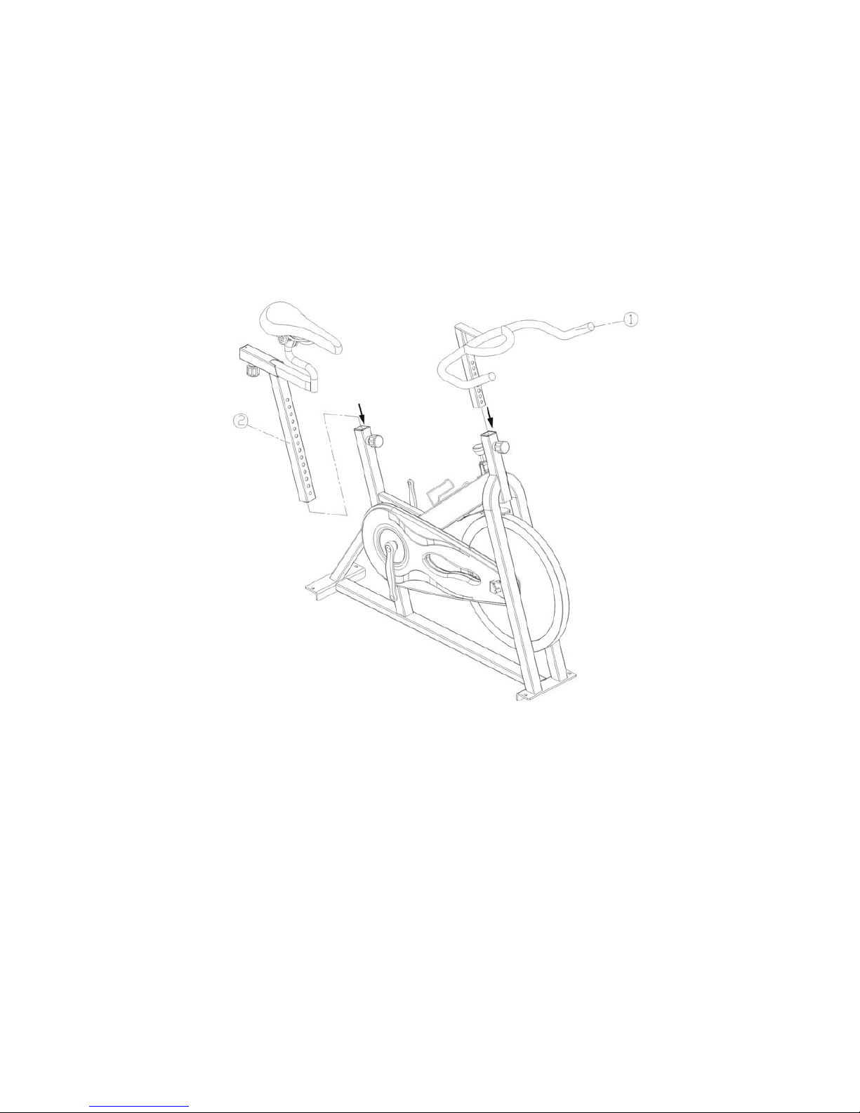
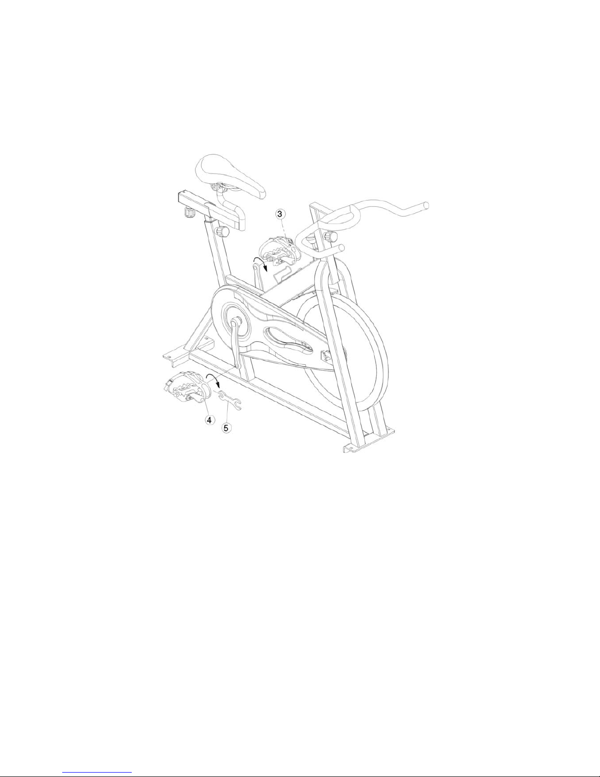
3. Please always check the seat post, seat slider, pedals and handlebar are
secured firmly before getting on the bike.
4. To lubricate all moving parts monthly is recommended.
5. Do not wear loose clothing to avoid entangling in any moving parts.
6. Do not remove feet from the pedals while they are in motion.
7. Always wear shoes when using the machine.
8. Dry the bike after each use to remove sweat and moisture. Wipe the machine
with a damp cloth, water and mild soap. Do not use a petroleum-based
solvent to clean the machine in order not to damage the finish .
9. Please keep children away from the bike while it is in use. Do not allow
children to use the bike. This bike is designed for adults, not children.
10. Do not dismount the bike until the pedals have stopped completely.
11. Stop exercise immediately in case of nausea, shortness of breath, faint,
headache, pain, tightness in your chest or any discomfort.
12. Do not place fingers or any other objects into the moving parts of the bike.
13. Prior to any exercise, consult with your physician first to establish the
exercise frequency, time and intensity appropriate for your particular age
and condition.
14. After exercising, please turn the tension control knob clockwise (+) to
increase resistance so that the pedals will not rotate freely and possibly hurt
someone.

4
Multi-positioned Handlebars
Multi-positioned handlebars for a comfortable and variable workout
Resistance Adjustment
Easy-to-use resistance control knob provides incremental resistance
adjustments, while, pushing down for emergency brake
Micro-adjustable Seat
Micro-adjustable position for various body types
Water Bottle Cage
Holds heavy bottle for thirst quenching
Cast Iron Flywheel
High-momentum flywheel simulates the feel of road riding
Chain Guard
Pretty guard attracts users’ attention
Welded Steel Frame
Robotic welded rigid frame structure provides maximum stability at
high speed
Direct-Drive
Having a direct drive system that allows the users to pedal either
forward or backward

5

6
Bill of Material
Drawing No
Description Q'TY
1 Flywheel 1 PC
1-1 Hub Set 1 SET
1-2 ( L ) Flywheel Cover ( L ) 1 PC
1-2 ( R ) Flywheel Cover ( R ) 1 PC
1-3 Self-Tapping Screw 6 PCS
1-4 Flange Nut 2 PCS
2 Rear Stabilizer 1 PC
2-1 Leveling Feet 4 PCS
2-2 End Cap 4 PCS
2-3 Pan Allen Bolt 4 PCS
2-4 Washer 4 PCS
3 Frame 1 SET
4 Front Stabilizer 1 SET
4-1 Transportation Wheel 2 PCS
4-2 Washer 4 PCS
4-3 Allen Bolt 2 PCS
4-4 Nylon Nut 2 PCS
5 Handlebar 1 SET
5-1 End Cap (for H/B) 2 PCS
6 Seat Post 1 SET
6-1 Sleeve 3 PCS
6-2 Adjustable Knob 3 PCS
7 Seat Slider 1 SET
7-1 End Cap (for Seat Slider) 1 PC
7-2 Saddle 1 SET
8 Water Bottle Cage 1 PC
9 Tension Control Knob 1 SET
9-1 Spacer 1 PC
9-2 Upper Brake Cap 1 PC
9-3 Allen Bolt (M5) 6 PCS
9-4 Helical Compression Spring 1 PC
9-5 Square Nut 1 PC
9-6 Allen Nut 1 PC
9-7 Cap Nut 1 PC
9-8 Rubber Absorber 1 PC
9-9 Beam 1 PC
9-10 Brake Pad Assembly 1 SET
9-11 Round Head Screw 2 PCS

7
9-12 Washer 4 PCS
9-13 Nylon Nut 2 PCS
10 Water Bottle 1 PC
11 Inner Chain Guard W/O Sticker 1 PC
12 Chain 1 PC
13 Outer Chain Guard W/O Sticker 1 PC
14 Pedal Set 1 SET
15 Pan Self Tapping Screw 4 PCS
16 Pan Self Tapping Screw 3 PCS
17 Chain Guard Spacer 1 PC
18 Allen Bolt 2 PCS
19 Allen Nut 2 PCS
20 Bottom Bracket 1 SET
21 Chain Wheel 1 PC
22( L ) Crank ( L ) 1 PC
22-1 Crank Bolt 2 PCS
22-2 Crank Cap 2 PCS

8
ASSEMBLY INSTRUCTION
■ PARTS LIST
NO DESCRIPTION Q’TY SPECIFICATION
1 Handlebar 1 Racing Style
2 Seat Post 1 With seat slider
3 Left Pedal 1 Deluxe
4 Right Pedal 1 Deluxe
5 Adjustable Wrench 1
6 Front Stabilizer 1 With transportation wheels
7 Rear Stabilizer 1 25* 50 * 2T * 450L
8 Allen Bolt 4
9 Washer 4
10 Allen Wrench 1

9
■ASSEMBLY STEPS
Prior to assembly of this product, remove all components from the package and verify all the listed
parts are supplied. Once certain, begin with the first assembly step.
STEP (A)
A1: Pull the pop pin and insert the handlebar(1) into the handlebar receptor and secure with the
pop pin.
A2:Pull the pop pin and insert the seat post (2) into the receptor and secure with the pop pin.

10
STEP (B)
B1:Attach the left pedal (3) and the right pedal (4) by adjustable wrench(5).
Please be aware that the pedals are marked L and R on the flat face of the
threaded area. The left and right pedals are referenced from a seated position on the bike. The left
pedal has a left-hand thread and must be tightened counterclockwise, and the right pedal must be
tightened clockwise.
B2: Tighten the pedals with the adjustable wrench supplied in your package.

11
STEP (C)
C1: Mount the front stabilizer (6) using two allen bolts(8) and two washers (9). Then tighten clockwise
using the allen wrench included in your package.
C2: Mount the rear stabilizer (7) using two allen bolts(8) and two washers (9) . Then tighten clockwise
using the allen wrench included in your package.
C3 : Apply your computer upon the handlebar as the instruction described in computer’s package.

12
OPERATION
Emergency Brake
This bike can be stopped immediately when pushing
down the tension knob.( Fig. 1 ).
Resistance Adjustment
Pedaling resistance is controlled by the tension control
knob ( Fig. 1 ). To increase resistance, turn the tension
control knob clockwise (+). To decrease resistance,
turn the tension control knob counterclockwise (-).
Resistance adjustment can be easily made at any time.
Leveling the Bike
This bike can be leveled to compensate for uneven
surfaces. To level the bike, please raise or lower four
leveler feet located on the underside of the front and
rear stabilizers.( Fig. 2 ).
Seat Adjustment
Appropriate seat height helps upgrade your exercise
efficiency & reduce the risk of injury and make you
feel more comfortable. Adjusting the seat forward or
backward helps you work on different lower body
muscle groups.
1. Place your foot in the toe clip, then get in the bike.
2. If your leg is bent too much, you should move the
seat up. If your foot can not touch the pedal or your
leg is too straight, you should move the seat down.
3. Dismount the bike. Loosen and pull the pop pin
( Fig. 3 ), then raise or lower the seat post to the
desired position.
4. Loosen and pull the pop pin ( Fig. 4 ), then move the
seat slider forward or backward to the desired
position. When the seat slider is in the desired
position, secure the pop pin firmly.
Fig.1

13
Handlebar Adjustment
Loosen and pull the pop pin ( Fig. 5 ), then raise or
lower the handlebar to the desired position for a more
efficient & comfortable ride. Make sure the pop pin
settles into the desired hole and then secure it firmly.
Pedal Strap Adjustment
Place the ball of each foot in the toe clip until the front
of the shoe fits snugly in the toe clip cage. Rotate one
foot to within arm’s reach, then pull up the strap until
the toe clip cage fits the shoe snugly ( Fig. 6 ). Repeat
for the other foot.
Workout
Once you are sitting comfortably, begin pedaling
slowly, with your hands resting comfortably on the
handlebar. After you feel secure, you can change seat
positions, hand positions and resistance levels for
added enjoyment and variety during your workout.
Dismounting the Bike
Increase the resistance by turning the tension control
knob clockwise until the flywheel stops, or pedal
slower until you come to a complete stop.
Warning !
Do not dismount the bike or remove your feet from
the pedals until the pedals have completely
stopped.
Moving the Bike
Carefully lift the rear stabilizer to move the bike to
another location ( Fig. 7 ). Please gently move the
bike as any sudden impact may affect the operation
of the machine.
Table of contents
Other Joy Sport Exercise Bike manuals