JP 4F400212C01 Parts list manual

Fuel stove and air integrated parking heater
Technical Description, Installation, Operation and Maintenance Instructions
Idle cooking is forbidden
Production Type Order No.
Double stoves Diesel DC12V 4F400212C01
Single stove Diesel DC12V 4F400212C21
Jan. 25th,2022

Thank you for using the parking heater
This manual describes the technical description, installation,
operation and maintenance instructions for the parking heater. To
ensure the correct use of the heater please read this manual carefully
before installation and use. Please keep it properly after reading it. For
review.
Note:
●The contents of this manual are subject to change without prior
notice, but the instructions are guaranteed to be consistent with the
products purchased.
●We try our best to express the problems that users should know
through the instructions. If you have questions or find something
wrong, please contact us directly.
●When the user unpacks for the first time, check the main unit and
accessories against the packing list. If you find any problems,
please contact the dealer immediately.
●If there is a problem in use, please contact the company's
marketing department or our authorized customer service station.
We will be happy to help you.
Please carefully save the after-sales service warranty sheet and
provide feedback as required. This sheet is the only valid proof of
after-sales service.
Note:
Must be installed and used in accordance with the requirements of the
manual to ensure long-term use of the product!
Subject to Change

1
1.Application
Air and stove heater (hereinafter referred to as
the fuel stove) is an integrated stove, heating
air as one of the special RV fuel stove.The
stoves can also be used for cooking in the wild,
such as on ships.
2. Main Technical Data
Table1
3. Function
This fuel stove is a safe diesel stove with no
open flame.The fuel stove is not allowed to be
used during running.
--Cooking mode
Adjust the heating power by controlling the
switch to cook and heat various kinds of food
-- Air conditioning mode
Close the upper cover and adjust the setting
temperature by controlling the switch to heat
the room temperature.
4. Safety instructions
Safe working environment
-- The danger of toxic fumes.If the vehicle is
parked in a closed room, in an enclosed space
(such as a garage, repair shop), the exhaust gas
from the fuel stove can be toxic.Therefore, in
the enclosed space to turn off the fuel supply of
the fuel stove, through the control switch to
turn off the fuel stove.
-- Thermosensitive objects (e.g., spray cans) or
flammable materials/liquids should not be
stored in the same compartment as the
equipment because, in some cases, the area
may be affected by high temperatures.
-- At all times, keep exhaust pipe and
combustion air inlet free from contamination
(slush, ice, leaves, etc.).
Obligations of the operator/owner
It is the owner's responsibility to operate the
equipment correctly.
The fuel system must comply with the
technical and administrative regulations of the
state.Must abide by national legislation and
regulations.
Safe operation
-- Make sure the interior is well
ventilated.When the burner is turned on, there
may be some smoke or odor due to dust or
dirt.Especially if the equipment has not been
used for a long time.
-- The integrity and tight fit of the intake and
exhaust pipes must be checked periodically,
especially at the end of a long journey.
Do not spray water directly into the exhaust
hood while cleaning the vehicle.
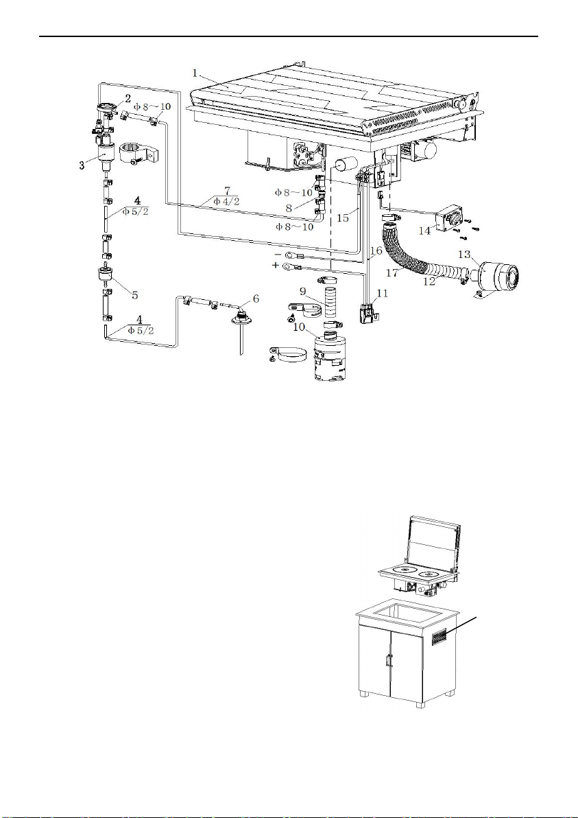
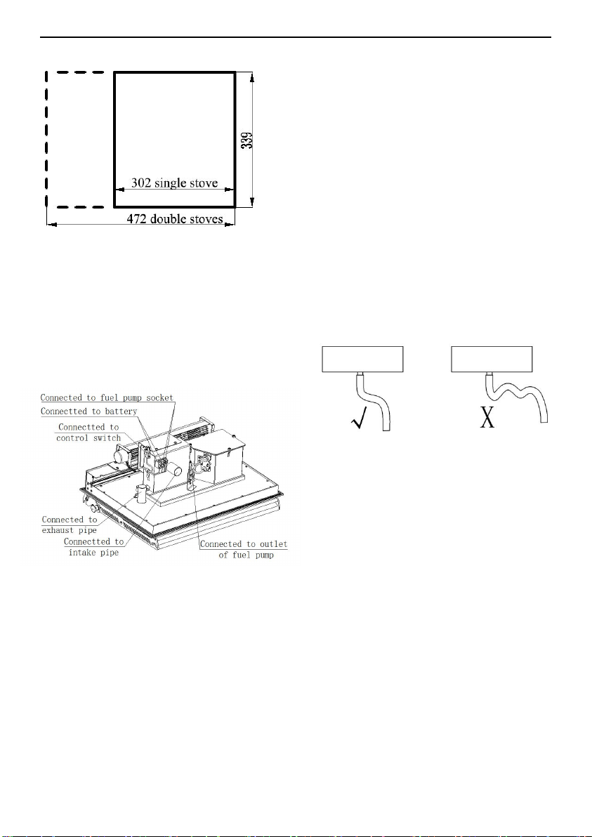
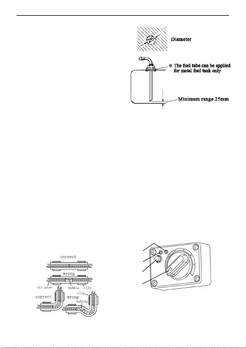
5. Installation
Typical installation diagram of fuel stoves
figure 1.
★Must be authorized by the company's
professional installation, maintenance!
The Company shall not be liable for any of the
following ACTS:
-- Refitting fuel stoves and accessories.
-- Modification of exhaust pipe path and
accessories.
-- Do not follow the operation installation
instructions.
-- Do not use our special accessories.
--Overheat damage caused by idle burning or
Double stoves
Single stove
Type
FJH-2.2/1C SZ N
FJH-1.8/1C DZ N
Rated Voltage
DC12V
Short-term Maximum Power
Consumption
8-10A
Average Power Consumption
0.55~0.85A
Heat Power
900-2200W
900-1800W
Fuel type
diesel
Fuel Consumption
110-264ml/h
110-192ml/h
Quiescent current
1mA
Warm Air Delivery
vvolumem3/H m3/h
148m3/h max
141m3/h max
Working Environment
Temperature
-25℃~+35℃
Working Altitude
≤5000m
Heater Weight
11.8kg
8.8kg
Dimensions(mm)
492×359×200
326×359×250
Stove vent
≥100cm2
≥40cm2

2
dry boiler burning.
Schematic diagram of fuel stove installation.As
shown in figure 2.
Fuel stoves should be installed horizontally,
with an inclination Angle of no more than 5° at
an upright level.If the fuel range is tilted too
much during operation (up to several hours),
the equipment may not be damaged, but will
affect the combustion effect, the burner is not
up to optimal performance.
Below the fuel stove should retain enough
space for installation accessories, this space
should maintain enough air circulation channel
with the outside, need more than 100cm2
ventilation cross section, in order to achieve
the equipment heat dissipation and
air-conditioning mode when the need for warm
airs.
Fig.1
1-Heater 2-Buffer 3-Fuel pump 4-Fuel pipe (blue:fuel tank to fuel pump) 5-Fuel filter 6-Fuel suction
pipe 7-Fuel pipe(white: heater to fuel pump) 8-Check valve 9-Air inlet pipe 10-Air filter (optional)
11-Fuse holder 12-Exhaust pipe 13-Fireproof cap 14-Control switch
15-Fuel pump lead wire 16-Power cord17-Insulated sleeve
Fig.2
Stove vent

3
Opening size of diesel cooking stove
Between the fuel stove and the stove is fixed
with glass glue. After fixing for one day, the
fuel stove can be used.Open the doors and
Windows after fixing the fuel stove to ventilate
the smell.
Schematic diagram of fuel stove external
connection line
Installation of inlet and outlet pipes
The combustion air must be inhaled from the
fresh air outside the vehicle;The exhaust gas
from combustion must be discharged into the
atmosphere through the exhaust pipe, and must
not enter the car.Prevent the exhaust gas from
burning to cause the danger of poisoning.
Pipe line through the vehicle's outer wall or
bottom through hole, must be able to seal to
prevent exhaust entry.
Inlet pipe and exhaust pipe must be equipped
with accessories of this machine.
The connection between the intake pipe and
exhaust pipe and the main engine shall be
fastened on the combustion inlet and exhaust
pipe with matching clips.The outlet of the
exhaust pipe should be positioned so that the
discharged gas is not taken in by the intake
pipe or the car heating fan (i.e. away from the
intake pipe and car heating fan).
Inlet pipe and exhaust pipe, from the fuel stove
to the car, should use downward direction
(Figure 5), otherwise, in the lowest point of the
pipeline should open a 4mm condensation
water discharge hole.If bending is required, the
bending radius of the pipe shall not be less than
50mm.Moreover, the sum of all bending angles
of each tube must not exceed 270°.
When the fuel stove is working, the
temperature of exhaust pipe is very high.
When installing, it must be kept away from
hot objects such as plastic parts of the car
body and properly fixed.
Intake and exhaust pipes are easy to freeze in
winter and should be checked frequently for
patency.
Inlet pipe and exhaust pipe are stainless steel
bellows.The connection between the engine
and the combustion engine shall be fastened on
the inlet and outlet of the exhaust pipe
respectively with corresponding supporting
clips.
No coating should be added to the surface of
the fuel stove.
Warning: Failure to comply with the above
requirements may result in fire.
Fuel system connection
Fig. 5
Fig.3
Fig.4

4
Fig.6
The fuel is extracted from the vehicle fuel tank,
and the fuel is transported and adjusted through
a special fuel pump (provided by the
manufacturer).Fuel is not allowed to be
extracted from the vehicle engine's return
system or downstream of the vehicle's internal
delivery pump.Please install using fuel hoses
and piping within the delivery range.
Fuel fuel shall conform to national standards
Gb19147-2013 for vehicle diesel standard.
In winter, the fuel should meet the
requirements of low temperature, and no
biofuel should be used.
Fuel line system
Installation of fuel line
The pipeline must be supplied with this
machine fitting, namely nylon fuel pipe with
good light resistance and thermal
stability.Permissible length of fuel line: the
maximum length of fuel line on the inlet side is
2m, and the maximum length of the pressure
side is 6m.As shown in figure 6.
Safety code for fuel lines
Be sure to use a hose cutter or a sharp tool to
cut the fuel hose and piping to a certain
length.The cut area cannot be compressed and
must be free of burrs.Fuel lines must be firmly
connected to prevent damage and/or noise due
to vibration (approximately 50 cm is
recommended between connection points).Fuel
lines must be protected against mechanical
damage.The laying of fuel pipeline will not
adversely affect the stability of vehicle rotation
and engine operation.Protect fuel carrying parts
from high temperatures that may affect
operation (use suitable fiberglass lined
aluminum thermal protective hoses).Do not
install or fix fuel line near heater or exhaust
line of vehicle engine.If the lines are crossed,
keep sufficient distance from the hot parts -- if
necessary, provide a thermal radiation
shield.The tubing should be installed in a way
that prevents flying stones from hitting, away
from hot parts of the vehicle, and protective
devices should be installed if necessary.
Installation of fuel pump
The fuel pump shall be fixed with the fuel
pump fixed jacket (rubber).The fuel outlet of
the fuel pump should tilt upward, and its
installation Angle should be selected within the
range of 15° ~ 35° (As shown in Fig.7).When
conditions permit, the tubing between the fuel
pump and the heater should rise gradually.To
prevent the fuel pump from heating (maximum
operating temperature 40℃), do not install
near the exhaust pipe.
a≤3m b≤0.5m (Avoid of negative pressure
may be produced in sealed fuel tank.
In such case, b≤0.15m) c≤2m.
1-Fuel pump 2-Max.fuel level
3-Min.fuel level 4-Fuel inlet level
①Allowable installation angle
②Optimum installation angle
Fig.7

5
Fig.9
The height difference between the fuel level
and the pump, and the height difference
between the pump and the main engine inlet,
will generate pressure (or suction) in the fuel
path, so these dimensions should be in
accordance with the requirements in Figure 7
(in a closed tank, negative pressure will be
generated, in which case, the minimum fluid
level maximum diagram of the tank should not
exceed 0.4m).
Connection between heater and fuel pump
The tubing direction from the fuel pump to the
main engine should be as upward as
possible.Mark a suitable place on the floor of
the vehicle for crossing
The hole where the fuel line and fuel pump are
connected to the cable.Before drilling, be sure
to check for hidden cables, fuel lines, frame
sections, etc.Then seal with underbody
protection
The edge of an opening in the floor of a
vehicle.In order to prevent the cable between
fuel pipe and fuel pump being cut, please add
the inlet bushing or the section edge protection
material.
Tubing should be tied in an appropriate place
for fixation, and the binding spacing should not
be greater than 50cm.
The connection between fuel pipe and fuel
pump, main engine and fuel tank (fuel
extractor) should use the fuel pipe joint
provided by this machine and tighten with the
fuel pipe clip.Prevent bubbles from forming at
the junction (Figure 8).
Installation of fuel suction pipe(Fig9)
Used when drawing fuel from the vehicle's
own tank.During installation, the 25±0.2 hole
size of the installation hole on the fuel tank (or
fuel tank cover) shall be noted, with neat edges
and smooth surroundings to ensure a good seal
between the fuel suction tubing seat.The
distance between the lower mouth of the
suction pipe and the bottom of the fuel tank
should be 30-40mm, which can not only ensure
the full absorption of fuel fuel, but also prevent
the impurities deposited at the bottom of the
fuel tank from being inhaled.
Mounting control switch
The fuel stoves must be operated by special
rotary switches.See related instructions for
details.
Fig.8
3
4
2
1
Fig 10
1- Control knob 2- Function button
3- Cooking indicator (red)
4-Air conditioning indicator (green)

6
Wiring diagram
.
Insert the control switch cable plug into the
corresponding position as shown in Figure 4.
The red and green light at the same time on and
off after power on .
If the red and green lights do not respond when
power on, the knob switch may not be
connected or the main power supply is not
connected.The communication between the
heater and the knob switch is defective if the
red and green light flickers 10s when the power
is on.
The cooking mode is adjusted by turning the
control knob.The power range is between
900W and 2200W.
The air conditioning mode is controlled by a
knob to set the temperature.The temperature
setting range is 5℃ ~ 35℃.
Electrical connection
Lay electric wire to avoid chafing.If there are
sharp edges, such as metal panels for threading,
use lead bushing or edge protection.
Connector cables shall not attach to or touch
metal surfaces, exhaust pipes or hot air pipes.
DC12V power supply
The electrical wiring, switches and control
equipment for the fuel stoves must be located
in a location that will not adversely affect their
operation under normal operating conditions.
The fuel stove circuit has reverse polarity
protection.If the controller is not connected
with the correct polarity, the LED indicator
will not work.
To ensure optimal power supply, the fuel stove
must be connected to a fusible (20A) The
length and cross-sectional area of the power
line shall ensure that the allowable voltage
drop is not greater than 0.5V and 1.0V when
the voltage is 12V and 24V. It is recommended
to configure the power cord according to the
following table.
Plus cable + minus cable
cross section
<8m
2.5mm2
8~12m
4mm2
12~16m
6mm2
Fig11

7
6. Operation instructions
Start fuel stove
Operate with a special knob switch.
If cooking function is needed, long press the
function button over 2S and the cooking
function will start.The fuel stove began to work
when cooking indicator light turns red after a
few seconds, adjust the control knob after
Igniting and burning steadily,power range
between 900W ~ (1600W) 2200W.Set the
power scale from 1 to 7 In cooking mode and
increase the knob scale from left to right.The
fuel stove needs more than 5 minutes from
startup to stable combustion.
If you need air conditioning function, press
the function button and the red light goes
out.Switch to air conditioning mode when the
green light turns on.
Adjust the knob switch to set the required room
temperature after stable combustion, and the
fuel stove automatically adjusts the combustion
power according to the ratio of the actual room
temperature and the set temperature.
If you need to change to air conditioning mode
during cooking mode, you must press the
function button and close the top cover for
conversion.You can't just button the top cover
without switching to air conditioning mode.
If you press the function button again, switch
back to cooking function.
Turn off fuel stoves
The fuel stove can be turned off through long
press the function button for more than 2S
when the fuel stove is in normal operation.
Fuel stove stops supplying fuel for heating
after the corresponding indicator light goes off.
After the burner is turned off, the combustion
fan and heating fan will continue to operate for
several minutes to reduce the temperature of
the furnace and body.
7. Fault
General fault handling
During the use of the fuel stove, it may not
start normally or shut off by itself after starting
and be in the state of failure lock.At this point,
you can turn off the fuel stove more than 5S to
restart by pressing function button.
Fuel stoves may cause circuit faults due to the
following reasons: joint corrosion, poor contact,
wrong insertion, wire or fuse corrosion, battery
pile corrosion, etc., pay attention to the use of
inspection, maintenance, prevent these
phenomena occur.
When the following situations occur, they can
be handled and eliminated by the user:
● The fuel stove does not start and the control
switch indicator light does not light after
starting up, the reason is open fuse or wiring
error;In addition, check whether the plug on
the control switch lead is properly connected to
the host.
Fail-lock status
The fault of the fuel stove is shown by the
corresponding cycle flicker on the control
switch.Each cycle includes a 3s long snuff and
several flashes at intervals of 0.5s.The number
of flickers that occur between two long
extinguishment intervals indicates the type of
fault.
Press the function button to exit the fault
locking state.
The troubleshooting methods can be listed in
Table 2.

8
Troubleshooting methods of fault lock
Flash
frequency
Fault
code
fault handling
Method of troubleshooting
1
31
Start failure
A Check the fuel supply system
B. Check whether the combustibles inlet and
outlet are blocked
C Check the electric plug and flame sensor
2
32
Burner failure
A Check the fuel supply system
B. Check whether the combustibles inlet and
outlet are blocked
C Check the flame sensor
3
10
Overvoltage fault
A Check the vehicle power supply system
11
Low voltage fault
A Check the vehicle power supply system
4
33
Flame sensor failure
A Check the flame sensor lead
B Check the flame sensor
5
51
Communication failure
A Check the connection cable
6
25
Outside temperature sensor
broken circuit
A Check whether the sensor is in goo condition
26
Outside temperature sensor
short circuit
A Check whether the sensor is in good condition
7
61
Fuel pump broken circuit
A Check whether the fuel pump lead is damaged
B Check whether the fuel pump lead connection
is reliable
C repair fuel pump
D Replace the main board
62
Fuel pump short circuit
A Check whether the fuel pump lead is damaged
B Check whether the fuel pump lead connection
is reliable
C repair fuel pump
D Replace the main board
Table 2

9
Troubleshooting methods of fault lock
Flash
frequency
Fault
code
fault handling
Method of troubleshooting
8
81
Combustion fan broken circuit
A Check the combustion fan
82
Combustion fan failed to start
A. Check the motor lead
connection
B Check the combustion fan
83
Fan speed is too low
A Check the combustion fan
9
63
Glow plug broken circuit
A Check the supply voltage
B check the glow plug temperature
resistance (0.2 Ω / 12 v)
C. Clean the heating plug for
carbon deposition
D Replace the main board
65
Glow plug is not actuate
A Replace the main board
10
84
Fan broken circuit
ACheck warm air fan
85
The warm air fan failed to
start.
A Check the warm air fan B Check
warm air fan
86
speed of the warm air fan over
low
ACheck warm air fan
11
Heater cover overheat
A Check whether the sensor is in
good condition
12
Short circuit of heater cover
temperature sensor
A Check whether the sensor is in
good condition
Broken circuit of heater cover
temperature sensor
A Check whether the sensor is in
good condition
B Check the cable
13
Heater cover temperature
overheat
A Incorrect control mode
14
Pneumatic sensor failure
A Replace control switch
Table 2 continued

10
8. Notes
● First installation
- The first installation of the fuel stove, in order
to completely remove the air in the fuel supply
system, so that the fuel pipeline filled with fuel,
we set a special pump fuel function.Knob the
switch in the minimum position, press the
function button then knob the switch right to
the maximum position, and knob the switch
left to the minimum position, then the red light
is on, knob the switch in the middle position,
Both the red light and green light flashes at the
same time, and the fuel pump began to pump
fuel quickly.Default pump time is 90s.If any
key is pressed during the fast fuel pumping, the
fast fuel pumping stops.
-- The fuel stoves should be tested before
use.Carefully check all connections for leaks
and safety during the trial run.In case of smoke
emission, abnormal combustion noise or fuel
odor, turn off the heater and unplug the fuse so
that it cannot operate.After professional
maintenance can be used.
The first time you use a fuel stove, it may take
a short time
Smell.This is normal in the first few minutes of
operation, and it does not mean that the fuel
stoves are not functioning properly.
Maintenance
- During maintenance, an inspection must be
conducted by a professional to carry out the
following maintenance work:
Check inlet and outlet for contamination and
foreign matter.
Clean the outside of the fuel stove.
Check the circuit connector for rust and
looseness.
Check the intake and exhaust pipes for
obstruction or damage.
Check the fuel line for leaks.
● Long-term shutdown
-- When the fuel stove is not in use for a long
time, it should be operated once every 4 weeks
for about 10 minutes each time to prevent
failure of mechanical parts such as combustion
air fan (fixed).
- When replacing low-temperature fuel, make
the fuel stove run for at least 15 minutes and
fill the fuel system with new fuel.
● Fuel stove use life
-- The heat exchanger for the fuel range shall
not be used for more than 10 years.After
expiration, it must be replaced by genuine parts
and replaced by the fuel stove manufacturer or
its authorized agent.
The exhaust pipes from the fuel stoves that
discharge combustion gases must be replaced
with genuine parts when they have been in use
for 10 years.
● Other precautions
-- In the process of transportation and storage,
the ambient temperature should not exceed
-40℃ ~ 85℃ to prevent damage to electronic
components.
- Only authorized customer service stations are
allowed to install and repair the heater, and the
use of non-original parts is prohibited to avoid
risks.
The manufacturer is not responsible for the
warranty of heater damage caused by improper
installation and operation.
You must turn off the fuel range before
refueling.
- When welding the car, first remove the
positive power line of the fuel stove from the
battery and ground it to prevent damage to the
controller.
This manual suits for next models
1
Table of contents
Other JP Heater manuals
Popular Heater manuals by other brands

Fakir
Fakir RF-O9 TURBO manual

Pinnacle Climate Technologies
Pinnacle Climate Technologies PROTEMP PT-45-KFA User's manual & operating instructions

Superior Radiant
Superior Radiant eWAVE Series Installation, operation and service instructions

Saunum
Saunum Professional Instructions for use and installation

Clas Ohlson
Clas Ohlson 36-4586 instruction manual

Dimplex
Dimplex PFH30E instruction manual