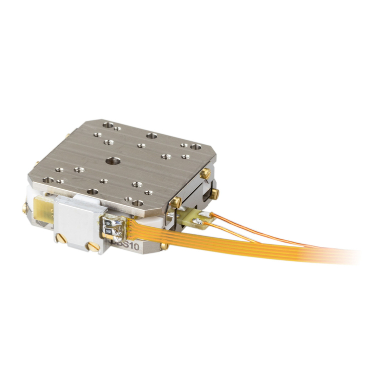
JPE CRYO STAGE 02 User manual

Page 1 / 11
JPE
+31 (0) 43 3585 777
Property of: JPE
Last update: 2021-07-08
www.jpe.nl
Author: JPE
Revision: 03
Aziëlaan 12
Filename: CNP_MAN01-04_R03_CS02.docx
Doc status: Released
6199 AG Maastricht-Airport
The Netherlands
MAN01-04 –CRYO STAGE 02 (CS02) USER MANUAL
CRYO & NANO PRODUCTS

MAN01-04 –CRYO STAGE 02 (CS02) USER MANUAL
Cryo & Nano Products
Page 2 / 11
Property of: JPE
Last update: 2021-07-08
Author: JPE
Revision: 03
Filename: CNP_MAN01-04_R03_CS02.docx
Doc status: Released
CONTENTS
1. INTRODUCTION 4
1.1 Prerequisites 4
2. INSIDE THE BOX 5
3. MOUNTING INSTRUCTIONS 6
4. CONNECTING TO THE CONTROLLER 7
4.1 Drive Signal 7
4.2 Position sensor signal 8
4.3 Connecting to Controller 8
5. SENSOR CALIBRATION 10
6. DECLARATION OF CONFORMITY 11

MAN01-04 –CRYO STAGE 02 (CS02) USER MANUAL
Cryo & Nano Products
Page 3 / 11
Property of: JPE
Last update: 2021-07-08
Author: JPE
Revision: 03
Filename: CNP_MAN01-04_R03_CS02.docx
Doc status: Released
RELEVANT DOCUMENTATION
Ref
Title, Author
[1]
CNP_MAN00_Rxx_Getting-Started.pdf (JPE)
[2]
CNP_MAN02_Rxx_Software-User-Manual.pdf (JPE)
[3]
CNP_APN01_Rxx_Connection-Overview.pdf (JPE)
[4]
CS02_Interface-drawings.pdf (JPE)
[5]
CS02_Brochure.pdf (JPE)
DOCUMENT HISTORY
Author
Date
Comment
JPE
2019-06-20
R01. Creation.
JPE
2021-02-01
R02. Update.
JPE
2021-07-08
R03. Update.
DEFINITIONS
Definition
Description
ABBREVIATIONS
Abbreviation
Description

MAN01-04 –CRYO STAGE 02 (CS02) USER MANUAL
Cryo & Nano Products
Page 4 / 11
Property of: JPE
Last update: 2021-07-08
Author: JPE
Revision: 03
Filename: CNP_MAN01-04_R03_CS02.docx
Doc status: Released
1. INTRODUCTION
Thank you for using JPE’s Cryo & Nano Products!
This User Manual describes the handling and use of Cryo Stage 02 (CS02), from here on described as
stage).
Please read this document carefully prior to installation and (initial)
operation of the controller, (stand-alone) positioners, actuators and
stages. Failure to observe the safety regulations results in a risk of electric
shock and/or damage to the controller(s), positioner(s), actuator(s) and/or
stage(s)!
JPE shall not be liable for damage or injury resulting from misuse of the
controller(s), positioner(s), actuator(s) and/or stage(s) or unauthorized
alterations to either of those.
All products mentioned in this manual are intended for use in a laboratory and/or scientific research
environment only and may only be installed, maintained and used by higher educated, technical skilled
personnel (from here on described as operators).
Please note that all content in this document is superseded by any new versions of this document. Visit
the JPE website (www.jpe-innovations.com) to obtain the most recent version. All images in this
document are for illustrative purposes only.
1.1 Prerequisites
Before continuing with this user manual, please make sure to read and understand the contents of the
(latest version of the) Cryo & Nano Positioning Products Getting Started Guide (MAN00).

MAN01-04 –CRYO STAGE 02 (CS02) USER MANUAL
Cryo & Nano Products
Page 5 / 11
Property of: JPE
Last update: 2021-07-08
Author: JPE
Revision: 03
Filename: CNP_MAN01-04_R03_CS02.docx
Doc status: Released
2. INSIDE THE BOX
Stages will be delivered in a white-colored (membrane) polypropylene box (one stage per box). The
stage is fixed onto the inner part of the polypropylene using fasteners. The inner part can be taken out
and bend in such way that the stage can be easily unpacked.
Do not cut the membrane plastic. Keep the box in case products need to be returned.
Unpacking stages require a bit more attention as it can be easy to damage cabling (flex PCB) or
connectors.
Figure 1: Example packaging with 1x CS021-RLS

MAN01-04 –CRYO STAGE 02 (CS02) USER MANUAL
Cryo & Nano Products
Page 6 / 11
Property of: JPE
Last update: 2021-07-08
Author: JPE
Revision: 03
Filename: CNP_MAN01-04_R03_CS02.docx
Doc status: Released
3. MOUNTING INSTRUCTIONS
Consult the Interface Drawing for detailed dimensions and mounting interfaces.
Make sure the wiring to the Connector Interface PCB and/or Sensor (product type option -RLS) does not
get damaged or stuck in the setup when mounting the stage in the customer setup. All connectors must
be mounted properly prior to connecting the stage to the electronics!
An optional reference frame (I1-CS021) is also available. If ordered, this reference frame will be delivered
pre-mounted on the CS021(-RLS). However, the frame can also be removed by the customer if desired.

MAN01-04 –CRYO STAGE 02 (CS02) USER MANUAL
Cryo & Nano Products
Page 7 / 11
Property of: JPE
Last update: 2021-07-08
Author: JPE
Revision: 03
Filename: CNP_MAN01-04_R03_CS02.docx
Doc status: Released
4. CONNECTING TO THE CONTROLLER
Consult the Connection Overview application note for a simple and clear overview on how to connect
positioners to the controller.
4.1 Drive Signal
All positioners in the stage are assembled with ~150[mm] Kapton coated wire and a Connector Interface
PCB at the end with a 2-pin 2.54mm pitch header mounted (Molex KK 22-05-7028). There are two
mounting holes available for M2 bolts.
Figure 2: Connector Interface PCB (top view)
Figure 3: Connector Interface PCB
The Ambient Cable (ACL) or Cryostat Cable (CCL) can be connected directly to the Connector Interface
PCB. If any custom cabling is required, please consult the Getting Started Guide (MAN00) or the
Connection Overview application note (APN01).
Please consult the Interface Drawing to determine which Connector Interface PCB corresponds to which
positioner (X-axis, Y-axis, Z-axis or Z-scan) since all PCBs are identical.
Pin configuration
Pin
Name
Note
1
(Piezo) Signal
Routes to the pad labeled “S” or “SIG” on the positioner
2
(Piezo) REF
Routes to the pad labeled “R” or “REF” on the positioner
Make sure that there is no force applied to the wires connected to the positioners!
Please note that (Piezo) REF is NOT the same as (system) GND or PE, so do not connect these to each
other and do not use standard oscilloscope probes!
Because of design constraints, open voltage contacts are present!

MAN01-04 –CRYO STAGE 02 (CS02) USER MANUAL
Cryo & Nano Products
Page 8 / 11
Property of: JPE
Last update: 2021-07-08
Author: JPE
Revision: 03
Filename: CNP_MAN01-04_R03_CS02.docx
Doc status: Released
4.2 Position sensor signal
If the positioners in the stage are equipped with Resistive Linear Sensors (product type option –RLS), the
stage is assembled with an additional ~150[mm] Kapton FPC (flexible PCB) that can connect directly to
the Cryostat Cable for RLS (CCR) or Ambient Connector Kit for RSM (I1-RSM).
If any custom cabling is required, please consult the Getting Started Guide (MAN00) or the Connection
Overview application note (APN01).
Figure 4: FPC (for 3 axis) connected to CCR (right)
Figure 5: RLS X- / Y- / Z-axis reference (PFC top view)
Pin configuration (for each axis)
Pin
Name
RLS PCB Reference
1
Wiper Negative
A
2
Excitation Positive
B
3
Wiper Positive
C
4
Excitation Negative
D
Make sure that there is no force applied to the FPC connected to the sensor! The FPC is designed for
easy connection at (re-)installation; however, it’s recommended to disconnect or reconnect only when
required.
4.3 Connecting to Controller
Controller with Plug-in Modules 1
Module
Slot #
CS02 (X)
CADM2 Output
1
CS02 (Y)
CADM2 Output
2
CS02 (Z)
CADM2 Output
3
CS02 (Z-scan)
CADM2 Output or
PSM Output A
4
CS02-RLS (X)
CADM2 Output
1
CS02-RLS (Y)
CADM2 Output
2
CS02-RLS (Z)
CADM2 Output
3
1
For available Modules see CNP-Products MAN01-09 (CPSC).

MAN01-04 –CRYO STAGE 02 (CS02) USER MANUAL
Cryo & Nano Products
Page 9 / 11
Property of: JPE
Last update: 2021-07-08
Author: JPE
Revision: 03
Filename: CNP_MAN01-04_R03_CS02.docx
Doc status: Released
CS02-RLS (X)
RSM Input A
4
CS02-RLS (Y)
RSM Input B
CS02-RLS (Z)
RSM Input C
CS02(-RLS) (Z scanning)
CADM2 Output or
PSM Output A
5

MAN01-04 –CRYO STAGE 02 (CS02) USER MANUAL
Cryo & Nano Products
Page 10 / 11
Property of: JPE
Last update: 2021-07-08
Author: JPE
Revision: 03
Filename: CNP_MAN01-04_R03_CS02.docx
Doc status: Released
5. SENSOR CALIBRATION
If the stage is equipped with Resistive Linear Sensors (product type option –RLS), the device will be
delivered pre-calibrated. This calibration is done to determine the (maximum) stroke the sensor can
measure as well as the center (nominal) position.
Calibration is done in cooperation with the Resistive Sensor Module (RSM). This means that the
calibration settings for a specific RLS will be stored for a specific input channel of the RSM.
For that reason, or for a re-calibration, it is also possible to do a manual calibration. This involves moving
the positioners through their ranges (free movement required) and storing measurement calibration
values. This can all be done with the user software, please read the Software User Manual (MAN02) on
how to do this.

MAN01-04 –CRYO STAGE 02 (CS02) USER MANUAL
Cryo & Nano Products
Page 11 / 11
Property of: JPE
Last update: 2021-07-08
Author: JPE
Revision: 03
Filename: CNP_MAN01-04_R03_CS02.docx
Doc status: Released
6. DECLARATION OF CONFORMITY
Manufacturer
:
JPE B.V.
Address
:
Aziëlaan 12
6199 AG Maastricht-Airport
The Netherlands
The manufacturer hereby declares that the product:
Product Name
:
Cryo Stage 02 (CS02)
Product Description
:
Orthogonal xyz positioning with high load capacity, fitting a
50mm bore.
Product Number
:
C181103
Complies with the following European directives:
2014/35/EU
Low Voltage Directive
2014/30/EU
EMC Directive
2011/65/EU
RoHS
A copy of the Technical file for this equipment is available at JPE.
Maastricht-Airport, 20 June 2019
Ir. H. Janssen
Founder & CEO
JPE B.V.
The Netherlands
This manual suits for next models
1
Table of contents
Other JPE Laboratory Equipment manuals