2
▋▋About▋the▋Proportional▋System
This company cannot be responsible for any accident
or failure that may occur from any modication of this
product, use of non-genuine parts, natural disaster, or
nonobservance of the precautions described in this
manual.
Further, for damages caused by an accident or failure,
please understand that items (excepting this product
and this Company’s genuine parts) such as airplanes,
competitor’s products, etc will not be covered under the
warranty.
The use of radio waves required by this product is
dened in the Radio Law of Japan.
▋▋Basic▋Precautions▋for▋Safe▋Use▋of▋
the▋2.4GHz▋System
The 2.4GHz band is not exclusively for use with
RC airplanes. This frequency band is in common
use with the ISM (industry, science, and medical
care) band which is widely used for short-distance
transmission such as microwave ovens, wireless
LAN, digital cordless phones, audio games, cellphone
Bluetooth, and VICS. Therefore, the steering
response of the 2.4GHz system may be degraded
in an urban area. Further, as it is also used for ham
and local area radio communications for mobile
identification, please pay attention to possible
influences from these. In the event of any adverse
radio wave interference on an existing wireless
station, immediately stop emitting radio waves and
take interference avoidance measures.
At a race track/aireld, minimize use of device that
can affect the transmitter/receiver and be sure
to confirm safety beforehand. Also, always follow
instructions given by the facility sta.
If an aircraft is allowed to fly behind a building,
a pylon, trees, etc. so that the radio-wave range
is blocked, the steering response may drop, even
resulting in an “out-of-control” situation. Always let
the aircraft fly within a range that can be visually
observed.
▋▋Indications▋and▋Symbols▋Related▋
to▋Safety
The following symbols used in this manual indicate the
precautions regarding possible danger which may occur
following improper handling. Be sure to strictly observe
them, as they contain important safety instructions.
If incorrect operation methods are used, there will
be a danger of death or serious injury.
DANGER
CAUTION
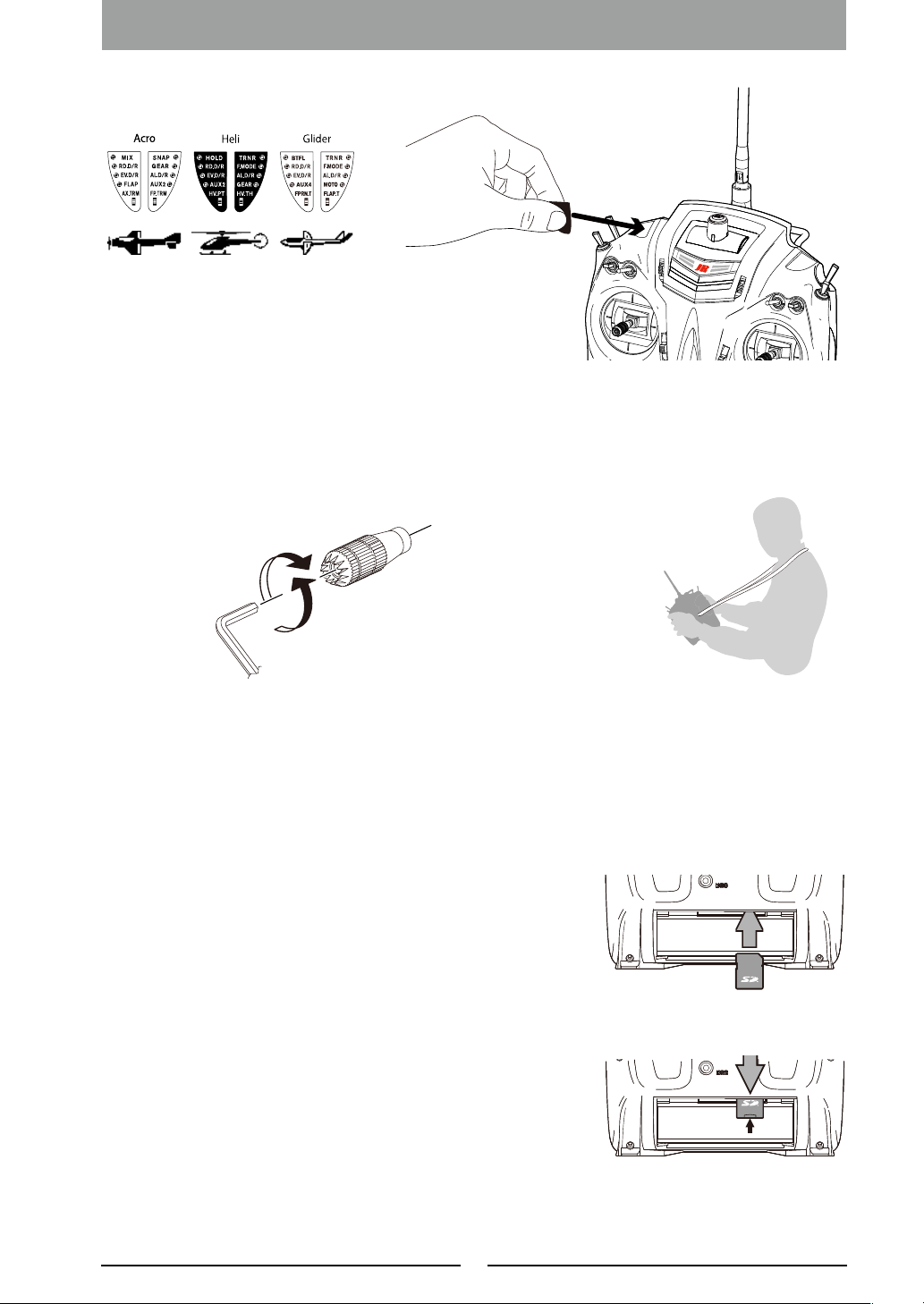
Helicopter
Airplane
Glider
WARNING
If incorrect operation methods are used, there will be a
possibility of death or serious injury.
DANGER
CAUTION
Helicopter
Airplane
Glider
WARNING
If incorrect operation methods are used, it can be expected
that there will be a possibility of problems occurring.
CAUTION
Helicopter
Airplane
Glider
WARNING
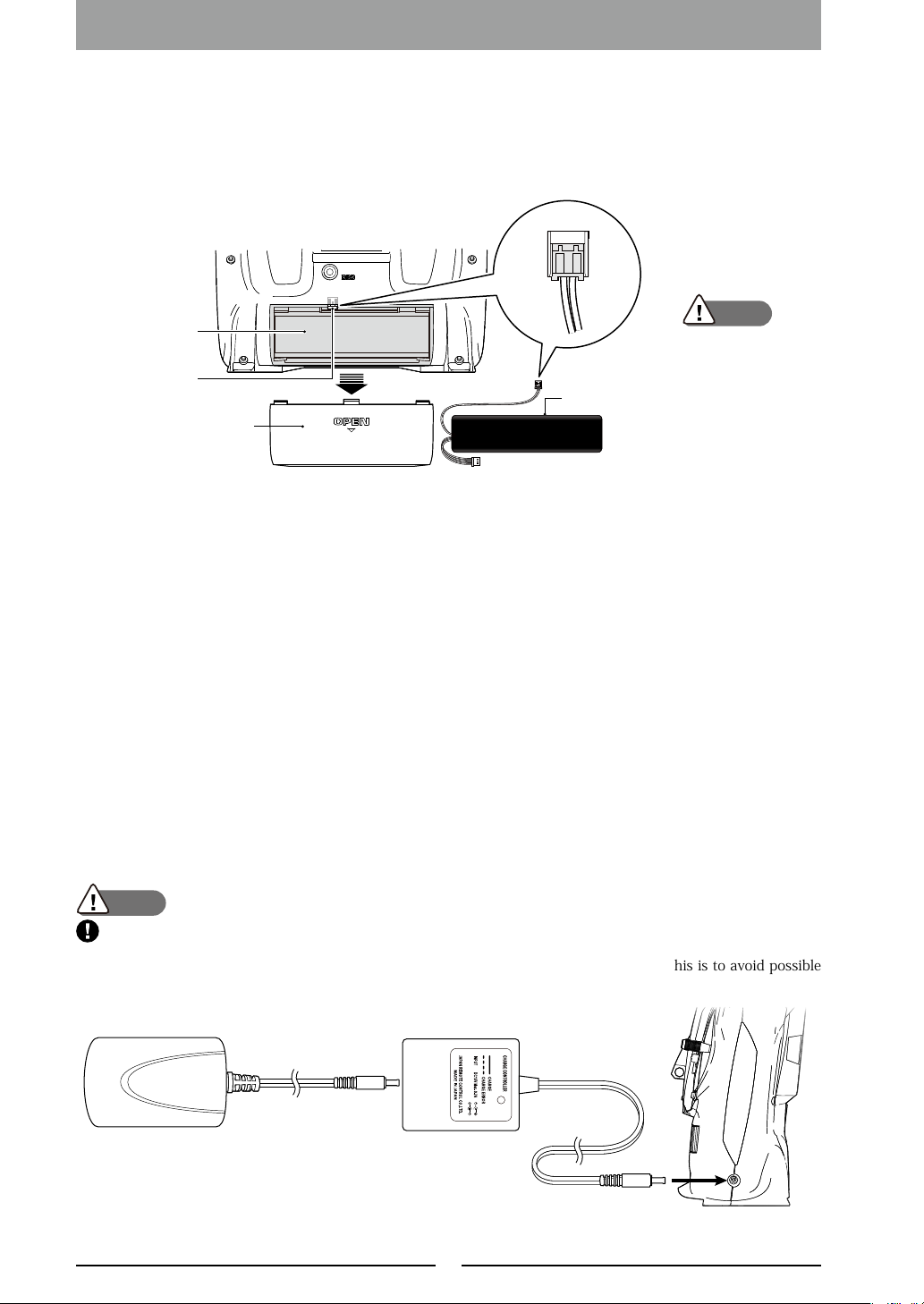
▋▋How▋to▋Handle
Before starting use, make sure that all the parts are provided.
Then, connect the switch harness and servo to the receiver,
and insert batteries into the transmitter/receivers. Turn
on the transmitter/receiver and confirm that they operate
correctly. If they do not operate, check the batteries. If a
rechargeable battery is used for the rst time after purchase
or is used after being left unused for a long period, be sure to
charge it with the battery charger before use, and confirm
the transmitter and receiver are correctly bound.
Refer to the Page 10 "Binding Procedure
(pairing the transmitter and receiver)"
In the event of any missing parts, malfunction, etc., please
contact your JR agent or distributor in your country.
Out-of-controlanddangeroussituationscanbe
caused.
DO NOT use the product on rainy days since it
may cause malfunction if water gets inside the
transmitter/receiver. If use is a necessity, be sure to
take waterproof measures.
Injuryduetoheatgeneration,fire,orelectric
shockcanoccur.
Never disassemble or modify this product.
Theengineandthemotor(inthecaseofan
electrically-drivenmodel)canstartrotatingat
highspeed,causingdanger.
When turning on the power switch, set the
transmitter throttle stick to the lowest speed position
(where the engine/motor rotation does not become
high) and turn on the transmitter power switch and
the receiver power switch in this order.
For turning o power, turn o the receiver and then
transmitter in this order.
When this product is used overseas, authorization
by the law of the country will be required.
When this product is used overseas for a purpose other
than as radio control system for a model, it may be
subject to the restrictions in accordance with the Export
Trade Control Order. In such a case, an export permit
under the Order is required.
This indicates actions that are forbidden.
This indicates actions that must be implemented.
DANGER
CAUTION
Helicopter
Airplane
Glider
WARNING
Introduction
▋General▋Safety▋Precautions
* It is very important to ensure that you
observe the following precautions.