JRC DGPS224 User manual

DGPS224(JLR-4341)
1/20
DGPS SENSOR
JLR-4341
<INTRODUCTION>
<NOTES TO USERS>
In order to ensure safe and correct use of the equipment, symbols in this manual and on the
equipment itself alert the user to important operational precautions that could prevent personal
injury or damage. The followings show such symbols and their meanings. Please read this
manual carefully and take note of these symbols.
Other Symbols and Their Meanings:
This symbol indicates that the action is prohibited.
This symbol indicates that the action must be taken.
CODE : 7ZPNA4162 JRC
WARNING This symbol indicates warning items that, if ignored,
may result in serious personal injury or even death.
Thank you for choosing the JRC GPS sensor DGPS224.
This manual describes Model DGPS224, JRC DGPS Sensor and Beacon receiver with Built-In
Antenna and SBAS capability.
•To ensure correct operation of the DGPS224, please read this Instruction Manual carefully before starting
to use.
•This manual should be kept on hand to provide as quick reference whenever you need it.
•It will also help you if you come across any problems in its operation.
This symbol indicates cautionary items that, if
ignored, may result in personal injury or physical
damage.
CAUTION
Prohibited
Do This
DGPS224

DGPS224(JLR-4341)
2/20
SECTION 1 GENERAL INFORMATION
1.1 Function
By receiving GPS signals from up to twelve satellites, DGPS224 sensor provides highly accurate
position fixing. Furthermore, the DGPS224 can implement DGPS measurement by receiving the
correction data, and can achieve the measurement of high accuracy than the GPS measurement.
1.2 Features
•Built-In Beacon receiver
The DGPS224 can implement DGPS measurement by receiving the correction data from
Beacon station, and can achieve the measurement of high accuracy than the GPS
measurement.
•SBAS function
The DGPS224 can implement DGPS measurement by receiving the correction data from SBAS
satellite (WAAS/EGNOS/MSAS), and can achieve the measurement of high accuracy than the
GPS measurement.
•RAIM function
The accuracy of position fixes is self-tested by the equipment. (RAIM function)
This function assures higher reliability to the position fix than conventional method.
•Twelve-channel, twelve-satellite tracking, and all in view
Highly accurate position fixing is ensured by simultaneous tracking of up to twelve satellites by
twelve channels.
•Switching between IEC61162-1,NMEA0183 versions 1.5, 2.1 and 2.3.
The data output conforms to IEC61162-1 or NMEA 0183, and version switching is possible. This
feature allows the unit to be connected with various types of marine equipment including radars,
fish finders, and plotters.
1.3 Items Supplied
Table 1-1 indicates a listing of items that are included with your DGPS224.
Table 1-1 Components of the DGPS224
No. Name Model Code Q'ty Notes
1 DGPS Sensor JLR-4341JLR-43411 Including 15m (49.5ft) cable with
connector
2 Instruction Manual 7ZPNA4162 7ZPNA4162 1
3 Cable Guard Rubber MPPK31468 MPPK31468 1
4 Warranty Card
Europe
North America
Asia/Oceania
7ZPBS2901C
7ZPBS2902D
7ZPBS2903C
1
1
1
Option
1 Extension Cable CFQ-9000 CFQ-9000 1 15m cable with connector

DGPS224(JLR-4341)
3/20
SECTION 2 PARTS AND FUNCTIONS
1
2
3
4
6
5
①SENSOR: GPS signals from up to twelve satellites and provides highly accurate position fixing.
②CABLE: Supplies DC power for the sensor and inputs/outputs data to a navigation equipment.
6-wirecable
③BASE: Mount unit which conforms to 1"×14 NPT standards.
With this, the sensor can be installed onto a antenna mount or extension mast.
④CONNECTOR: Hooks up the sensor to a navigation equipment. 6-pin
12VDC/24VDC (Red)
0VDC (Black)
Data Common (White)
Data Output (Green)
Set Data Input (Yellow)
Not Use (Brown)
Fig. 2.2 Arrangement of Connector
①Sensor
②Cable 15m
③Base
④Connector
φ134mm
155mm
Mounting Screw
1"-14UNS-2B
Fig. 2.1 Parts of DGPS224
Mass:Approx. 1.7Kg

DGPS224(JLR-4341)
4/20
SECTION 3 INSTALLATION
3.1 Unpacking and Checking
Take out the DGPS224 from the packing case carefully. Check each item listed in Table 1-1 is
contained in the case. Save the case and the packing material until the equipment will be installed
successfully. In case the equipment is to be returned, kindly use the kept packing material.
3.2 Locating the Position for Installation
When connecting the cable attached to the equipment, do not bend it
acutely, twist it, or impart excessive force. Doing so sometimes causes
cracks or damage to the coating, resulting in fire or electrocution.
Do not install the sensor where there is excessive vibration.
Vibration may cause sensor failure.
Do not paint the sensor.
Doing so may result in reception problems.
Install the sensor where there are no obstacles, in order to ensure that
GPS signals can be directly received from satellites without
interference or reflection of signals from surrounding objects.
Whenever possible, select a place with the following characteristics.
If it is difficult to find an ideal site, select a place temporarily and install the
equipment. Conduct a test to make sure that the proper performance can be
obtained and then fix the equipment in position. If it is installed at an improper
place, reception accuracy may be impaired.
1. An open space, which allows uniform reception of satellite signals.
2. Far away from any high power transmission antennas.
3. Outside radar beams.
4. Away from the INMARSAT antenna by at least 5 meters and outside the
INMARSAT beam.
5. Away from the antenna of a VHF transmitter and a direction finder
by at least 3 meters.
6. Away from a Magnetic Compass by at least 1 meters.
7. 3 meter or more away from amateur radio antennas.
CAUTION

DGPS224(JLR-4341)
5/20
3.3 Installation Procedure
3.3.1 Installation of the Sensor
The sensor base contains 1 inch 14UNS-2B screw holes. It can be attached to poles with cut male
screws, or off-the-shelf adapters.
(1) When performing attachment, always hold and turn the sensor base. Holding and turning the
radome may result in a large amount of force applied at the junction of the base and the radome,
resulting in damage to the sensor.
Do not apply force to the joint. Hold and turn the base.
(2) Secure the sensor cable in position with a clamp band as shown below to protect it against damage
due to vibration.
(3) When connecting an extension cable to the DGPS sensor, always seal with self-bonding tape in
order to waterproof the connector, and wrap this section with vinyl tape to protect it.
Radome
Base
Joint
Off-the-shelf
adapter, etc
Off-the-shelf
adapter, etc Clamp band
Cable
Fig.3-1 Installation
Fig. 3-2 Appearance

DGPS224(JLR-4341)
6/20
3.3.2 Installation of the Sensor to pass a cable through a pole
It is possible to pass cable into pole, when DGPS sensor attached to poles with cut male
screws. (1”-14 UNS-2A). In this case, Cable guard rubber (attached article) used.
(1) The cable is installed as following figure.
Do not bend the cable acutely. Doing so may result in damage to the cable.
Cable installation figure
(2) Cable guard rubber is set in DGPS sensor. See below.
Do not bend it acutely
Cable guard rubber
(attached article) Push all the way in
Fig. 3-4 How to fit Cable guard rubber in DGPS sensor
Fig. 3-3 How to Cable form

DGPS224(JLR-4341)
7/20
(3) When DGPS sensor attached to poles with cut male screws, round off the corners. See below.
(4) When performing attachment, always hold and turn the sensor base. Holding and turning the
radome may result in a large amount of force applied at the junction of the base and the
radome, resulting in damage to the sensor.
Do not apply force to the joint. Hold and turn the base.
1”14-UNS-2A
About 25mm
round off the corners
Radome
Base
Joint
Fig. 3-5 How to attached to poles and work example
Fig. 3-6 Attention at installation

DGPS224(JLR-4341)
8/20
3.4 Cable connection
3.4.1 Connection to Navigation Equipment that can be connected directly
CAUTION
When you connect the DGPS224 to the navigation equipment that is
possible to connect directly, confirm the type of connector and pin
arrangement beforehand. If the possibility of direct connection with
DGPS224 is not described in the manual of the navigation equipment,
confirm the all pin assignment. Incorrect pin connection may cause a
damage of the equipment.
When the DGPS224 is connected to directly connectable GPS navigation equipment, 12 VDC is
supplied from the equipment to the DGPS224. In this case, connect the 6-pin connector to the plug
where the GPS/DGPS label is attached on the rear panel of the equipment.
3.4.2 Connection to Navigation equipment that cannot be connected directly
CAUTION
Connect it taking care about the polarity of the power supply.
The faulty wiring might damage the DGPS224.
DGPS 224 is designed for the power supply of 12/24VDC.
If the power supply of over 40V is fed to the equipment,
It might be damaged.
Normally, the 12/24VDC power is supplied out of the DC power switchboard or main battery.
As the normal current of the equipment is approximately 0.15A, it is recommended using a fuse not
exceeding 2A in the power line.
When the initialization is not provided, leave pin 5 open.
Fig. 3.7 shows the connection with the equipment that cannot be connected directly.
①
②
③
④
⑤
⑥
3 White Data Common
4 Green Data Output
5 Yellow Set Data Input
6 Brown Not Use
6-Pin Connector
CB
Circuit Breaker
Battery
12/24VDC
+
-
1 Red 12/24VDC
2 black/Shield
0VDC

DGPS224(JLR-4341)
9/20
3.5 NMEA Version Switching
When the equipment is shipped from the factory, the NMEA output version is set to the version 1.5. If
you want to change the output data, please carry out the following procedure:
1. Connect pin 4 and pin 5 of the connector.
2. Turn on the DGPS224.
3. The output data is switch.
(If procedures 1-3 are repeated, the output data is switched to NMEA0183 Ver1.5, Ver2.1, Ver2.3,
IEC*1 and Beacon correction data sequentially.)
*1:IEC61162-1
SECTION 4 AFTER-SALES SERVICE
If the DGPS224 appears to be defective, check the connection again. If the equipment still
appears faulty after that, stop using the equipment and contact our representative or our sales
office directly.
During the warranty period, JRC representative or our company replaces your DGPS224
sensor free of charge. This warranty does not cover damage, which has occurred in transit, or
results from alteration, accident, misuse or abuse.
JRC needs to have the following information:
•Product name, model name, serial number, and purchase date
•Detailed failure conditions
•Name of the company/organization, address, and telephone number
•Contact name
For further information on after-sales service, please contact JRC representative,
JRC branch office or sales office. For details, see "Place of Contact" (page 10).
SECTION 5 DISPOSAL
Disposal of the DGPS224
The DGPS224 contains a lithium battery for memory backup.
Observe all the laws and regulations concerned when you dispose of the GPS sensor.
WARNING
Do not remove the cover of the DGPS224 otherwise it may cause fire,
electric shock, and malfunction. It may also cause poor
waterproofing.
WARNING
Do not throw lithium battery into the fire and overheat it.
It may cause an explosion and ignition.

DGPS224(JLR-4341)
10/20
SECTION 6 SPECIFICATIONS
・Sensor Type :Multichannel 12ch+SBAS 1ch
・Maximum Number of
Tracked Satellites :12 Satellites
・Accuracy :13m 2DRMS (HDOP≦4 SA off)
5m 2DRMS (Beacon DGPS)
7m 2DRMS (SBAS)
・SBAS :WAAS, MSAS, EGNOS
・Geodetic Datum :Selection among 46 geodetic datum (Default:WGS-84)
・Data input :Initial input, SBAS Setting input, Beacon Setting input
・Data output :Selection among NMEA0183, IEC61162-1
Selection among NMEA0183 Version 1.5, 2.1, 2.3 (Default:Version 1.5)
NMEA0183 Version 1.5:GGA,RMC,GLL,VTG
NMEA0183 Version 2.1:GGA,VTG,RMC,GLL,GSV,GSA,DTM,MSS
NMEA0183 Version 2.3:GGA,VTG,RMC,ZDA,GSV,GSA,DTM,MSS,GLL,
GBS,GRS,GST,GNS
IEC61162-1 :GGA,VTG,RMC,ZDA,GSV,GSA,DTM,MSS,GLL,
GBS,GRS,GST,GNS
・Reception Beacon Frequency :283.5~325kHz
・Selection of Beacon Station :Automatic or manual
・Power Supply Voltage :DC12/24V(+30%,-10%)
・Power Consumption :less than 2.5W
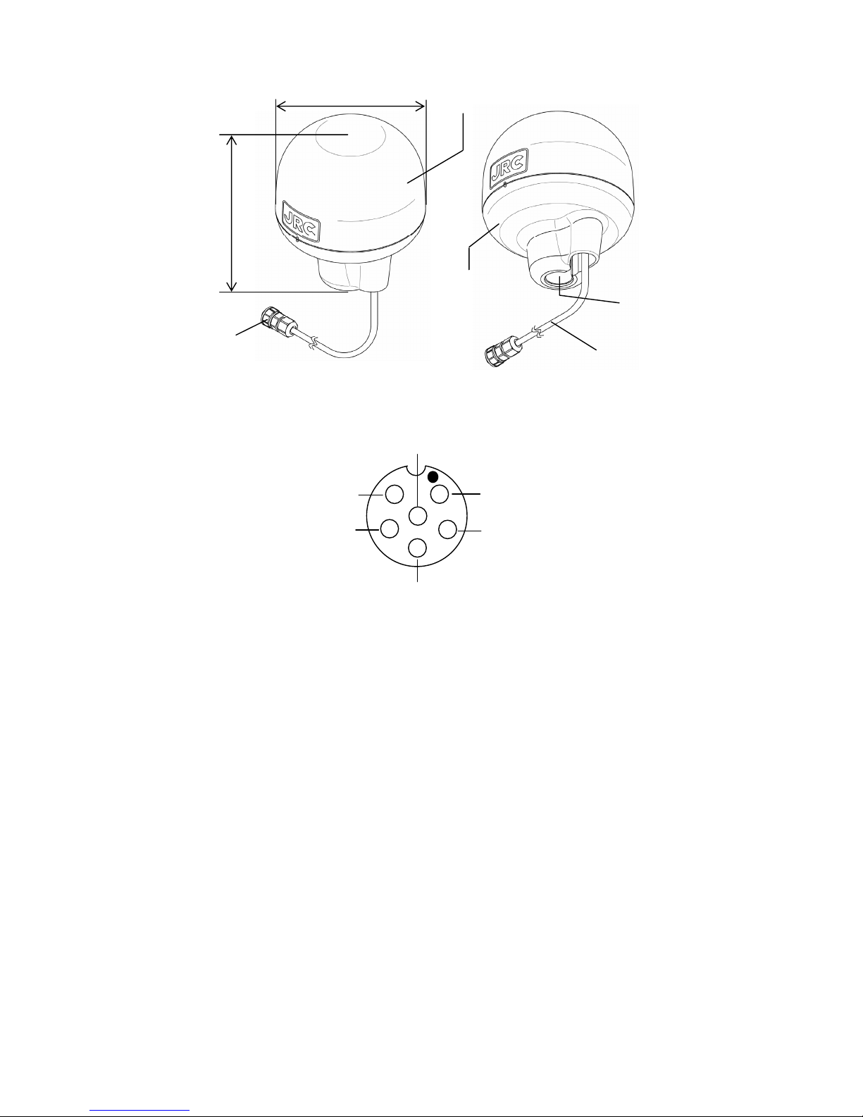
・Dimension :φ134m×155Hmm
・Mass :Approximately 1.7Kg
・Operation Temperature :-25℃~+55℃
・Storage Temperature :-25℃~+70℃
・Vibration :IEC60945 ed.4 conformant
・EMC :IEC60945 ed.4 comformant
・Waterproof :IP56
When the Lithium battery runs out, the settings are restored to the default values. In addition, it will take
about a minute for position fix. The battery life expires in about 10 years under the normal use
condition, but it may differ depending on the environment or use conditions.
PLACE OF CONTACT
TOKYO OFFICE
SEATTLE BRANCH OFFICE
AMSTERDAM BRANCH OFFICE
Nittochi Nishi-Shinjuku bldg.
10-1, Nishi-Shinjuku 6-chome, Shinjuku-ku,
Tokyo 160-8328 JAPAN
Phone : +81-3-3348-4126
Fax : +81-3-3348-4183
Web : http://www.jrc.co.jp
1021 SW Klickitat Way, Bldg. D,
Suite 101, SEATTLE, WA98134 USA
Phone : +1 (206) 654-5644
Fax : +1 (206) 654-7030
Web : http://www.jrcamerica.com
Cessnalaan 40-42 1119NL Schiphol-Rijk
THE NETHERLANDS
Phone : +31-(0) 20-658-0750
Fax : +31-(0) 20-658-0755
Web : http://www.jrceurope.com/

DGPS224(JLR-4341)
11/20
Appendix1 Data Format
1.Protocol
・Bit Rate :4800,9600,19200,38400bps selectable(Defaute:4800bps)
When power is turned on, bit rate is set to 4800bps.
・Data Bit :8 bit
・Parity :None
・Stop Bit :1 bit
・Output Interval :1 second
2.Output Data
(1)GGA (Global Positioning System Fix Data)
Version 1.5
$GPGGA, hhmmss,ddmm.mmm,a,dddmm.mmm,a,x,x,xx,uxxxx,M,uxxx,M,xx,xxxx<CR><LF>
1 2 3 4 5 6 7 8 9 10 11 12 13 14
Version 2.1
$GPGGA,hhmmss,ddmm.mmmm,a,dddmm.mmmm,a,x,xx,xx,uxxxx,M,uxxx,M,xx,xxxx*hh<CR><LF>
1 2 3 4 5 6 7 8 9 10 11 12 13 14 15
Version 2.3, IEC
$GPGGA, hhmmss.ss,ddmm.mmmm,a,dddmm.mmmm,a,x,xx,xx,uxxxx,M,uxxx,M,xx,xxxx*hh<CR><LF>
1 2 3 4 5 6 7 8 9 10 11 12 13 14 15
1 : UTC time (hours, minutes, seconds)
Measured UTC [1/100 sec] (Version 2.3, IEC)
2, 3 : Latitude (deg, min), N / S
4, 5 : Longitude (deg, min), E / W
6 : GPS measurement status
0 = No position measurement, 1 = GPS positioning, 2 = DGPS positioning
7 : Number of satellites used for position fix
8 : HDOP (0 – 20)
9, 10 : Antenna altitude above sea level (m), u: sign (+,-)
Thesignisomittedifvalueispositive.(IEC)
11, 12 : Geoid height (m), u: sign (+,-)
Thesignisomittedifvalueispositive.(IEC)
13 : Version 1.5 →DGPS data seconds expired
(NULLifnotperformingDGPSpositioning)
Version 2.1 →DGPS data seconds expired (00 if not performing DGPS positioning)
Version 2.3, IEC →DGPS data seconds expired
(NULLifnotperformingDGPSpositioning)
14 : Version 1.5 →DGPS reference station ID
Version 2.1 →DGPS reference station (0000 if not performing DGPS positioning)
Version 2.3, IEC →DGPS reference station (NULL if not performing DGPS positioning)
15 : Checksum
Note 1.
For version 1.5, when the position is not fixed, outputs last measured position data.
For version 2.3, IEC, when the position is not fixed, outputs last measured position data, date, and time.
For version 2.3, IEC, when power is turned on, or master reset is performed, the initial time, date, and
position settings are NULL.

DGPS224(JLR-4341)
12/20
(2)VTG (Track Made Good and Ground Speed)
Version 1.5
$GPVTG, xxx.x,T,,,xxx.x,N,,<CR><LF>
1 2 3 4
Version 2.1
$GPVTG, xxx.x,T,,,xxx.x,N,xxx.x,K*hh<CR><LF>
1 2 3 4 5 6 7
Version 2.3, IEC
$GPVTG, xxx.x,T,,,xxx.x,N,xxx.x,K,x*hh<CR><LF>
1 2 3 4 5 6 7 8
1, 2 : Course bearing (deg)
3, 4 : Speed (knots)
5, 6 : Speed (km/h)
7 : Checksum (Version 1.5, 2.1)
7 : Mode Indicator (Version 2.3, IEC)
A : GPS positioning
D : DGPS positioning
N : Not positioning
8 : Checksum (Version 2.3, IEC)
(3)RMC (Recommended Minimum Specific GPS/TRANSIT Data)
Version 1.5
$GPRMC, hhmmss,f,ddmm.mm,a,dddmm.mm,a,xxx.x,xxx.,xxxxxx,,*hh<CR><LF>
1 2 3 4 5 6 7 8 9 10
Version 2.1
$GPRMC, hhmmss,f,ddmm.mmmm,a,dddmm.mmmm,a,xxx.x,xxx.,xxxxxx,,*hh<CR><LF>
1 2 3 4 5 6 7 8 9 10
Version 2.3, IEC
$GPRMC, hhmmss.ss,f,ddmm.mmmm,a,dddmm.mmmm,a,xxx.x,xxx.x,xxxxxx,,,x*hh<CR><LF>
1 2 3 4 5 6 7 8 9 1011
1 : UTC time (hours, minutes, seconds)
Measured UTC [1/100 sec] (Version 2.3, IEC)
2 : Status A= Valid, V= Invalid
3, 4 : Latitude (deg, min), N / S
5, 6 : Longitude (deg, min), E / W
7 : Speed (knots)
8 : Course bearing (deg)
9 : UTC day, month, year
10 : Checksum (Version 1.5, 2.1)
10 : Mode Indicator (Version 2.3, IEC)
A : GPS positioning
D : DGPS positioning
N : Not positioning
11 : Checksum (Version 2.3, IEC)
Note 1
For version 1.5, when not performing positioning, outputs last measured position data.
For version 2.3, IEC, when not performing positioning, outputs last measured position data, date, and time.
For version 2.3, IEC, when power is turned on, or master reset is performed, the initial time, date, and position
settings are NULL.

DGPS224(JLR-4341)
13/20
(4)GLL (Geographical Position, Latitude / Longitude)
Version 1.5
$GPGLL,ddmm.mm,a,dddmm.mm,a<CR><LF>
1 2 3 4
Version 2.1
$GPGLL,ddmm.mmmm,a,dddmm.mmmm,a,hhmmss.ss,A*hh<CR><LF>
1 2 3 4 5 6 7
Version 2.3, IEC
$GPGLL,ddmm.mmmm,a,dddmm.mmmm,a,hhmmss.ss,A,x*hh<CR><LF>
1 2 3 4 5 678
1, 2 : Latitude (deg, min), N / S
3, 4 : Longitude (deg, min), E / W
5 : UTC time (hours, minutes, seconds 1/100 sec fixed at 00)
Measured UTC [1/100 sec] (Version 2.3, IEC)
6 : Status A= Valid, V= Invalid
7 : Checksum (Version 1.5, 2.1)
7 : Mode Indicator (Version 2.3, IEC)
A : GPS positioning
D : DGPS positioning
N : Not positioning
8 : Checksum (Version 2.3, IEC)
Note 1. For version 1.5, when not performing positioning, outputs last measured position data.
For version 2.3, IEC, when not performing positioning, outputs last measured position data,
date, and time.
For version 2.3, IEC, when power is turned on, or master reset is performed, the initial time,
date, and position settings are NULL.
(5)GSA (GPS DOP and Active Satellites)
Version 2.1 only
$GPGSA, a,x,xx,xx,xx,xx,xx,xx,xx,xx,xx,xx,xx,xx,xx.x,xx.x,xx.x*hh<CR><LF>
1 2 3 4 5 6 7 8 9 10 11 12 13 14 15 16 17 18
Version 2.3, IEC only
$GPGSA, a,x,xx,xx,xx,xx,xx,xx,xx,xx,xx,xx,xx,xx,xx.x,xx.x,xx.x*hh<CR><LF>
1 2 3 4 5 6 7 8 9 10 11 12 13 14 15 16 17 18
1 : Positioning mode M = manual selection, (2-D or 3-D fixed), A = automatic selection
2 : Positioning dimensions
1 = No position measurement, 2 = 2-D positioning, 3 = 3-D positioning
3 - 14 : Number of satellites used for positioning PRN number
(For less than 12 satellites, the field is "00".)(Version 2.1,JLR-4340)
15 : PDOP (4 digit fixed length) (Version 2.1)
16 : HDOP (4 digit fixed length) (Version 2.1)
17 : VDOP (4 digit fixed length) (Version 2.1)
18 : Checksum (Version 2.1)
3 - 14 : Number of satellites used for positioning PRN number
(For less than 12 satellites, the fields is NULL.)(Version 2.3, IEC)
SBAS satellites 120 to 138 are represented by 33 to 51
33 to 64 are reserved for SBAS satellite use.
If there are 12 or more GPS satellites when positioning, even if there are SBAS
satellites, the output gives priority to GPS
15 : PDOP (4 digit fixed length) (Version 2.3, IEC)
16 : HDOP (4 digit fixed length) (Version 2.3, IEC)
17 : VDOP (4 digit fixed length) (Version 2.3, IEC)
18 : Checksum (Version 2.3, IEC)

DGPS224(JLR-4341)
14/20
(6)GSV (GPS Satellites in View)
Version 2.1, 2.3, IEC only
$GPGSV, x,x,xx,xx,xx,xxx,xx,xx,xx,xxx,xx,xx,xx,xxx,xx,xx,xx,xxx,xx*hh<CR><LF>
1 2 3 4 5 6 7 8 9 10 11 12 13 14 15 16 17 18 19 20
1 : Total number of GSV messages (1 - 3) (Version 2.1)
2 : GSV message number (1 - 3) (Version 2.1)
1 : Total number of GSV messages (1 - 4) (Version 2.3, IEC)
2 : GSV message number (1 - 4) (Version 2.3, IEC)
3 : Satellites in view
4 : 1st satellite PRN number (01 - 32) (2 digit fixed length)
SBAS satellites 120 to 138 are represented by 33 to 51. (Version 2.3, IEC)
33 to 64 are reserved for SBAS satellite use. (Version 2.3, IEC)
5 : 1st satellite elevation angle (00 - 32) (2 digit fixed length)
6 : 1st satellite bearing angle (00 - 90 deg) (3 digit fixed length)
7 : 1st satellite SNR signal strength C/No (00 - 99dB) (2 digit fixed length)
8 – 11 : 2nd satellite information (same as 4 - 7)
12 – 15 : 3rd satellite information (same as 4 - 7)
16 – 19 : 4th satellite information (same as 4 - 7)
Null fields are not required for unused sets when less than four sets are transmitted. (IEC)
20 : Checksum
Note. Each GSV sentence includes 4 satellites, so the number of GSV sentences varies based on
the number of satellites detected.
If bit rate is set to 4800bps, Maximum GSV message numbers are three (Max 12 satellites).
Therefore, if satellites in view are 12 GPS satellites and 1 SBAS satellite (total 13 satellites),
the GSV sentence is output only 11 GPS satellites and 1 SBAS satellite (total 12 satellites).
(7)DTM (Datum Reference)
Version 2.1, 2.3, IEC only
$GPDTM,ccc,,x.x,a,x.x,a,ux.x,ccc*hh<CR><LF>
1 2 3 4 5 6 7 8
1 : Datum symbol
W84 - WGS84
W72 - WGS72
IHO - datum code (Version 2.1: JRC proprietary value)
IHO - datum code (Version 2.3, IEC: IHO datum code)
(Please refer to "Tables 1 and 2" for datum code)
999 - user defined number
2, 3 : Latitude deviation (min), N / S Note 1)
4, 5 : Longitude deviation (min), E / W Note 1)
6 : Elevation deviation (m), u: sign (+,-) Note 1)
Thesignisomittedifvalueispositive.(IEC)
7 : Reference datum Null or W84 (Version 2.1,JLR-4340)
Reference datum Null or W84 (Version 2.3, IEC)
8 : Checksum
Note 1) Deviation length is not fixed
(8)ZDA (Date and Time)
$GPZDA, hhmmss.ss,xx,xx,xxxx,,*hh<CR><LF>
1 2 3 4 5
1 : UTC time (hours, minutes, seconds, 1/100 sec is fixed at 00)
2 : UTC day (01 - 31)
3 : UTC month (01 - 12)
4 : UTC year
5 :Checksum

DGPS224(JLR-4341)
15/20
(9)GBS (GPS satellite fault detection for RAIM)
Version 2.1, 2.3, IEC only
$GPGBS,hhmmss.ss,uxxx.x,uxxx.x,uxxx.x,xx,x.xxxxx,uxxxx.x,xxxx.x*hh<CR><LF>
1 2 3 4 5 6 7 8 9
1 : Measured UTC (hr. min. sec. 1/100 sec)
2 : Latitude estimated error [m] u: sign (+,-)
Thesignisomittedifvalueispositive.(IEC)
3 : Longitude estimated error [m] u: sign (+,-)
Thesignisomittedifvalueispositive.(IEC)
4 : Elevation estimated error [m] u: sign (+,-)
Thesignisomittedifvalueispositive.(IEC)
5 : Faulty satellite ID GPS: 1-32(NULL is inserted when faulty satellite cannot be
decided.)
SBAS satellites 120 to 138 are represented by 33 to 51.
33 to 64 are reserved for SBAS satellite use.
6 : Faulty satellite detection overlook ratio (0.00000 to 1.00000)
7 : Estimated bias [m] u: sign (+,-) The sign is omitted if value is positive. (IEC)
8 : Standard bias deviation [m]
9 : Checksum
(10)MSS (Beacon Receiver Status)
Version 2.1 only
$GPMSS,III,SSS,FFF.F,BBB*hh<CR><LF>
1 2 3 4 5
Version 2.3, IEC only
$GPMSS,III,SSS,FFF.F,BBB,x*hh<CR><LF>
1 2 3 4 5 6
1 : Signal level
2 : SNR
3 : Frequency
4 : Bit rate
5 : Checksum
5 : Beacon channel: 1 or Null (Version2.3, IEC)
6 :Checksum

DGPS224(JLR-4341)
16/20
3.Input Data
Interval of two input sentences must be more than 1 second.
(1)PJRCI,GP (Initial Position and Time setting)
$PJRCI, GP, llll.ll, a, yyyyy.yy, a, uxxxx, hhmmss, xx, xx, xxxx, A, A, A, A, A, A*hh<CR><LF>
1 2 3 4 5 6 7 8 9 10 1112131415 16
1,2 : Latitude (Degree, Minute), N/S
3,4 : Longitude (Degree, Minute), E/W
5 : Antenna height above mean-sea-level (m), u : sign (+,-)
6 : UTC (Hour, Minute, Second)
7 : Day (UTC)
8 : Month (UTC)
9 : Year (UTC)
10 : Flag of Lat/Lon setting A : Set, V : No set
11 : Flag of Antenna height setting A : Set, V : No set
12 : Flag of Date/Time setting A : Set, V : No set
13 : Flag of Master Reset A : Set, V : No set
14 : Flag of Cold Start Fix A : Set, V : No set
15 : Flag of Differential GPS fix A : Set, V : No set
16 : Checksum
Note1. When this sentence is input, GPS sensor is initialized according to the items 10 to 15.
Note2. This sentence must be sent after this first data output when power is on or master reset is executed.
Note3. Setting of the flag have the following priority. When flags of both high and low priority set at the same
time, only a flag of high priority is executed. If flag of same priority set, flags are executed at same time.
FLAG
1 Master Reset
2 Cold Start Fix
3 Lat/Lon setting
Antenna height setting
Date/Time setting
High
↑
PRIORITY
↓
Low 4 Differential GPS fix
Note4. Interval of two input sentences must be more than 7 second.
Note5. Power must not be off for 20 seconds after initial setting.
(2)PJRCE,GP,0 (GPS Sensor Mode Setting)
$PJRCE, GP, 0, x, xx, x, x, x, 00, 00, 00, 00, 00, 00, 0, xx*hh<CR><LF>
1 2 3 4 5 6 7
1 : Fix mode (default : 2)
0 : 2D 1 : 3D 2 : AUTO
2 : Elevation Mask (default : 5 degrees)
Range from 1 to 89 degrees
3 : DOP switch ( default : 1)
0 : less than 4 1 : less than 10 2 : less than 20
4 : Smoothing level ( default : 1)
0 : 40 seconds 1 : 10 seconds 2 : variable from 1 to 999 ( default : 2 seconds)
5 : Locale Geodetic System ( default : WGS-84) See Table 1
6 : Additional Local Geodetic System See Table 2
7 : Checksum
Note1. This sentence must be sent after the first data output when power is on or master reset is executed.

DGPS224(JLR-4341)
17/20
(3) E0 (Beacon manual setting)
E0BfBfBfBfDf (Binary data)
1 2 3
1 : Manual search setting
2 : Frequency Bf Bf Bf Bf : fff.f kHz
ex) 309.0kHz : B3B0B9B0
3 : Bit rate D5 : 50bps D6 : 100bps D7 : 200bps
(4) E1 (Beacon automatic setting)
E1E3 (Binary data)
1
1 : Automatic setting
(5) PJRCG,GP,0 (SBAS setting)
$PJRCG, GP, 0, x, A, x, A, x, A, xxx, A*hh<CR><LF>
1 2 3 4 5 6 7 8 9
1 : DGPS correction mode
1:BeaconDGPSFix 2:SBAS DGPS Fix 3:Beacon/SBAS DGPS automatic selection
4:reserved 5:reserved
2: Flag of DGPS correction mode setting A : Set V : No set
3: Ranging 0 : No 1 : Yes
4: Flag of ranging setting A : Set V : No set
5: Using of NG ( or under the test ) SBAS setting 0 : Not use 1 : Use
6: Flag of using of NG SBAS setting A : Set V : No set
7: SBAS satellite PRN number 000:Automatic selection 120~138 : Desired PRN number
8: Flag of SBAS satellite PRN number A : Set V : No set
9: Checksum
Note1. Under the condition that "Flag of Differential GPS fix" is "V" in the "PJRCI,GP" sentence and "DGPS
correction mode" is "1:Beacon DGPS fix" in the "PJRCG,GP,0" sentence, "Ranging", "Using of NG
SBAS setting" and "SBAS satellite PRN number" of "PJRCG,GP,0" sentence are not effective.
Note2. Even if each parameter from DGPS Correction Mode to SBAS Satellite PRN Number is not set
(When a flag is “V”), please set arbitrary effective values.
(6) PJRCC,GP,5 (Data bit rate setting)
$PJRCC, GP, 5, x, A, xxx.x, A, x, A*hh<CR><LF>
1 2 3 4 5 6 7
1 : Bit rate (bps) 0 : reserved 1 : reserved 2 : 4800 3 : 9600 4 : 19200 5 : 38400
2 : Flag of bit rate A : Set V : No set
3 : Reserve
4 : Flag of reserve No3 field A : Set V : No set
5 : Reserve
6 : Flag of reserve No5 field A : Set V : No set
7 : Checksum
(7)PJRCC,GP,6 (Position, Speed, Course Smoothing setting)
$PJRCC, GP, 6, xxx, A, xxx, A, xxx, A, xxx, A*hh<CR><LF>
1 2 3 4 5 6 7 8 9
1 : Position Smoothing level Range from 0 to 100 (default:10seconds)
2 : Flag of Position Smoothing level A : set V : No set
3 : Speed Smoothing level Range from 0 to 100 (default:10seconds)
4 : Flag of Speed Smoothing level A : set V : No set
5 : Course Smoothing level Range from 0 to 100 (default:10seconds)
6 : Flag of Course Smoothing level A : set V : No set
7 : Reserve
8 : Flag of Reserve No7 field A : set V : No set
9 : Checksum

DGPS224(JLR-4341)
18/20
(8)PJRCE,GP,2 (Station health, Smoothing setting)
$PJRCE, GP, 2, x, xxx*hh<CR><LF>
1 2 3
1 : Station health Range from 0 to 7 (default 5:JLR-4341 6:JLR-4340)
2 : Smoothing level Range from 0 to 99 seconds
Setting of variable smoothing level in PJRCE,GP,0
3 : Checksum
Table 1. Number of Local Geodetic Systems
No Local Geodetic System CODE
0 WGS-84 W84
1WGS-72 W72
2Tokyo Bessel TOY
3North American 1927(America) NAS
4North American 1927(Canada, Alaska) NAS
5European 1950(Europe) EUR
6Australian geodetic 1966(Australia) AUA
7Ordnance Survey of Great Britain(England) OGB
8NAD-83 **
9Use additional Local Geodetic System in 13 sequence
Table 2. Number of Additional Local Geodetic systems
No Local Geodetic System CODE
11 Adindan(Ethiopia, Sudan) ADI
12 ARC 1950(Botswana) ARF
13 Australian Geodetic 1984(Australia) AUG
14 Bermuda 1957(Bermuda Islands) BER
15 Bogota Observatory(Colombia) BOO
16 Campo Inchauspe(Argentina) CAI
17 Chatham 1971(Chatham Island) CHI
18 Chua Astro(Paraguay) CHU
19 Corrego Alegre(Brazil) COA
20 Djakarta(Sumatra) BAT
21 European 1979(Europe) EUR
22 Geodetic datum 1949(New Zealand) GEO
23 Guam 1963(Guam) GUA
24 Hayford 1910(Finland) **
25 Hjorsey 1955(Iceland) HJO
26 Indian(India, Nepal) IND
27 Ireland 1965(Ireland) IRL
28 Kertau 1948(West Malaysia, Singapore) KEA
29 L.C.5 Astro(Cayman Brac Island) LCF
30 Liberia 1964(Liberia) LIB
31 Luzon(Philippines) LUZ
32 Merchich(Morocco) MER
33 Minna(Cameroon) MIN
34 Nahrwan(Oman) NAH
35 Naparima,BWI(Torinidad, Tobago) NAP
36 Old Egyptian(Egypt) OEG
37 Old Hawaiian(Hawaiian Island) OHA
38 Pico de las Nieves(Canary Island) PLN
39 Provisional south American 1956(South America) PRP
40 Provisional south Chilean 1963(Southern Chile) HIT
41 Puerto Rico(Puerto Rico, Virgin Island) PUR
42 Qornoq(South Greenland) QUO
43 RT90(Sweden) ***
44 Santa Braz(Sao Maguel, Santa Maria Island) SAO

DGPS224(JLR-4341)
19/20
45 South American 1969(South America) SAN
46 Southwest Base(Faial, Graciosa, Pico, Sao Jorge,
Terceira Island)
**
47 Timbalai 1948(Brunei, East Malaysia) TIL
** : No appear in s-60
*** : CODE is not appeared in s-60
There is no CODE, JRC original local geodetic number is appeared.

DGPS224(JLR-4341)
20/20
形式名(Type): JLR-4341 名称(Name): DGPS Receive
r
铅 汞 镉 六价铬 多溴联苯 多溴二苯醚
(Pb) (Hg) (Cd) (Cr6+)(PBB) (PBDE)
GPS接收器
(Antenna) ×○××××
船内装置(Inboard Unit)
・显示装置(Display Unit)
・信号处理装置
(Processing Unit)
------
外部设备(Peripherals)
・选择(Options)
・电线类(Cables)
・手册(Documennts)
×○××××
部件名称
(Part name)
有毒有害物质或元素
(Toxic and Hazardous Substances and Elements)
○:表示该有毒有害物质在该部件所有均质材料中的含量均在SJ/T11363-2006 标准规定的限量要求以下。
(Indicates that this toxic, or hazardous substance contained in all of the homogeneous materials for this part is below the requirement in
SJ/T11363-2006.)
×:表示该有毒有害物质至少在该部件的某一均质材料中的含量超出SJ/T11363-2006 标准规定的限量要求。
(Indicates that this toxic or hazardous substance contained in at least one of the homogeneous materials used for this part is above
the limit requirement in SJ/T 11363-2006.)
有毒有害物质或元素的名称及含量
(Names & Content of toxic and hazardous substances or elements)
Table of contents
Other JRC Boating Equipment manuals