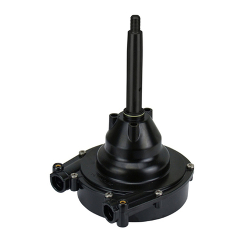
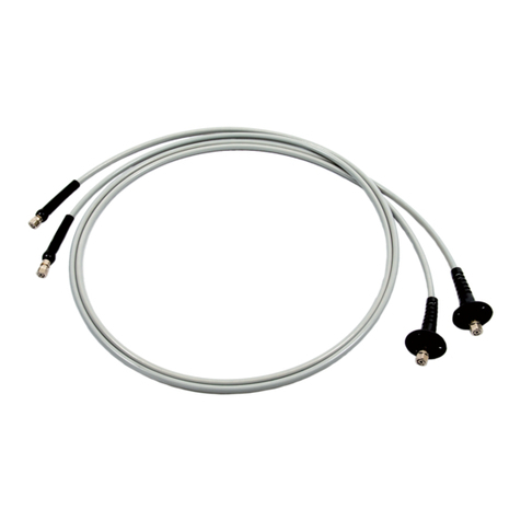
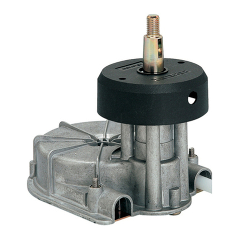
Ultraflex B 310 Manual

SINGLELEVER CONTROL
Installationandmaintenancemanual
R
B310
ITALIANO
(Dr./Dis./Des.n°25975/a13/02/2015)
ENGLISHITALIANOFRANÇAIS
PARTNER
I
UK F
page. 2 pag.21 page. 41

DearCustomer,
We wouldliketo thankyoufor choosingan ULTRAFLEX product.
ULTRAFLEX hasbeenaleader insteeringsystemsforpleasureandprofessionalboatsfor manyyears.
ULTRAFLEX productionissinceeversynonimousof reliabilityandsafety.
All ULTRAFLEX productsare designedandmanufacturedtoensurethebestperformance.
To ensure yoursafety andto maintainahighquality level, ULTRAFLEX productsare guaranteedonlyif
theyareusedwithoriginalspareparts.
ULTRAFLEX and UFLEX QualityManagementSystemsare certifiedCISQ-IQNet bytheItalianShipping
Registry(RINA),inconformitywiththeUNIENISO9001:2008 rule. ULTRAFLEX certificationNo.6669/02/S
(former420/96). UFLEX certificationNo.8875/03/S.
Thequality managementsysteminvolvesall thecompanyresourcesandprocessesstartingfromthe
design,inorderto:
- ensure productqualitytothecustomer;
-maintainandimprove thequality standardsconstantly;
-pursueacontinuous process improvementto meet themarket needsandto increasethecustomer
satisfaction
ULTRAFLEX EnvironmentalManagementSystemiscertifiedCISQ-IQNet bytheItalianShippingRegistry
(RINA),inconformitywiththeUNIENISO14001rule. ULTRAFLEX certificationNo.EMS-1282/S.
Productsforpleasure boatsare constantlytestedtochecktheirconformitywiththe2013/53/EU.
ULTRAFLEX S.p.A.
ULTRAFLEX
16015Casella(Genova)Italia -ViaCrose,2
"ULTRAFLEX hasover 80 yearsof experience inthemarineindustry andisaworldleader intheproduction
ofmechanical,hydraulicandelectronicsteeringsystems,controlboxesandsteeringwheelsforany
kindof pleasure,fishingor commercialboats.
Thekey factorswhichexplaintheincreasingsuccess of ourproductsall over theworldare thereliability
of ourproductsandthebefore andafter saleservice,thequality of thecompanyorganizationandof the
humanresourcesandthecontinuousspendinginresearchanddevelopment".
ENGLISH

SINGLELEVERCONTROLB310 -page 3 of63
Installationandmaintenancemanual
ULTRAFLEX
ENGLISH
SECTION1-PRODUCT DESCRIPTION
1.1 PRODUCTDESCRIPTIONANDRECOMMENDEDUSE..........................................................6
1.2 DIMENSIONS.................................................................................................................6
TABLEOF CONTENTS
SECTION2-TRANSPORT
2.1 GENERALWARNINGS............................................................................................................................7
2.2 PACKAGINGCONTENTS...........................................................................................................................7
SECTION6-MAINTENANCE
6.1 ORDINARYMAINTENANCE.................................................................................................................19
6.2 EXTRAORDINARYMAINTENANCE......................................................................................................20
SECTION3-INSTALLATION
3.1 NECESSARYTOOLS.................................................................................................................................8
3.2 THROTTLE REVERSING.....................................................................................................8
3.3 C2-C7-C8-MACHZERO CABLEINSTALLATION....................................................................9
3.3.1 SHIFTCABLECONNECTION............................................................................................9
3.3.2 THROTTLECABLE CONNECTIONWITHPUSHMECHANISM...........................................10
3.3.3 THROTTLECABLECONNECTIONWITHPULLMECHANISM.....................................................11
3.4 C14 ANDMACH14 CABLE INSTALLATION.......................................................................................12
3.4.1 SHIFTCABLECONNECTION.......................................................................................12
3.4.2 THROTTLECABLE CONNECTIONWITHPUSHMECHANISM......................................12
3.4.3 THROTTLE CABLECONNECTIONWITHPULLMECHANISM............................................13
3.5 X12 NEUTRALSAFETYSWITCHINSTALLATION....................................................................13
3.6 CONTROLBOXPOSITIONING.........................................................................................14
3.7 ASSEMBLINGB310LEVER-MECHANISM...........................................................................15
3.8 ADJUSTINGLEVERFRICTION.............................................................................................15
3.9 TRIMELECTRICALCONNECTIONS...........................................................................................................16
SECTION5-SAFETYWARNINGS
5.1 SAFETY WARNINGSDURINGINSTALLATIONANDUSE............................................................19
5.2 CLOTHES...........................................................................................................................19
SECTION7-DISMANTLING
7.1 DISMANTLING..............................................................................................................................20
!
USEOFTHEMANUALANDSYMBOLSUSED...................................................................................................4
INFORMATIONLETTER....................................................................................................................................5
WARRANTY..............................................................................................................................5
SECTION4-LEVER USE
4.1 LEVERUSE..............................................................................................................................18
4.2 NEUTRALWARM-UP.......................................................................................................................18
4.3 TRIMOPERATION................................................................................................................................18

Installationandmaintenancemanual
ULTRAFLEX
page 4 of63-SINGLELEVERCONTROLB310
ENGLISH
Inthismanualthefollowingsymbolsare usedtoensuretheuser safetyandtoguaranteethecorrect
operationoftheproduct:
USEOFTHEMANUALANDSYMBOLSUSED
THEINSTALLATIONAND MAINTENANCE MANUAListhedocument accompanyingtheproductfromits sale
toitsreplacementanddischarge.Themanualisanimportantpartoftheproductitself.
Itisnecessary toreadcarefullythemanual,beforeANYACTIVITY involvingtheproduct,handlingand
unloadingincluded.
STERN
BOW
STARBOARD
BULKHEAD
PORT
BULKHEAD
MOTORBOAT
Thedrawingsmakeiteasierto
undrstandsomenauticalterms
containedinthis manual.
SAILBOAT
STERN
BOW
PORT
BULKHEAD
STARBOARD
BULKHEAD
DANGER ImmediatehazardswhichCAUSEsevere personalinjury or death.
WARNING
CAUTION
Thesymbolasideindicatesall theoperations whichmust becarriedout
byqualifiedorskilledstaff,inordertoavoidhazards.
Werecommendtrainingthestaff inchargeoftheproductinstallation
andcheckingtheirknowledge.
NOTICE Important informationfor thecorrectinstallationandfor maintenance,that
doesnotcauseanydamage.
Denotesthatahazardexists whichcanresultininjury or death ifproper
precautions are nottaken.
Denotesareminder ofsafetypracticesordirectsattentiontounsafe
practiceswhichcouldresultinpersonalinjury or damagetothecraft or
components or totheenvironment.

SINGLELEVERCONTROLB310 -page 5 of63
Installationandmaintenancemanual
ULTRAFLEX
ENGLISH
WARRANTY
ULTRAFLEX guaranteesthatits products are well designedandfree frommanufacturingandmaterialdefects,
foraperiodoftwoyearsfromthedateofmanufacturing.
Fortheproductswhichare installedandusedonworkingorcommercialboatsthewarrantyislimitedto
oneyearfromthedateofmanufacturing.
Ifduringthisperiodtheproductprovestobedefectiveduetoimpropermaterialsand/ormanufacture,the
manufacturerwill repairor replace thedefective parts freeofcharge.
Directorindirectdamageisnotcoveredbythiswarranty.Inparticularthecompanyisnotresponsibleandthis
warrantywill notcover thedamageresultingfromincorrectinstallationoruseoftheproduct(exceptfor
replacementor repairofdefective partsaccordingtotheconditionsandterms above).
Thiswarrantydoesnotcover theproducts installedonrace boats or boats usedincompetitions.
Thedescriptionsandillustrations containedinthismanualshouldbeusedasgeneralreferenceonly.
For anyfurther informationpleasecontactourTechnicalAssistance Service.
ULTRAFLEX steeringsystemcomponents are markedaccordingtotheDirective 2013/53/EU.
Weremindyouthatonly markedsteeringsystemsmust beusedontheboats marked .Weinform
youthatthe ULTRAFLEX warrantyisnullifsome ULTRAFLEX componentsareinstalledonasteeringsystem
togetherwithproductsofotherbrands.
TECHNICALASSISTANCE SERVICE
INFORMATIONLETTER
UFLEX S.r.l.
ViaMiliteIgnoto,8A
16012Busalla(GE)-Italy
Ph.: +39.010.962.0239(Italy)
Ph.:+39.010.962.0244(Abroad)
Fax:+39.010.962.0333
Email: ut@ultraflexgroup.it
www.ultraflexgroup.it
North-South -CentralAmerica:
UFLEX USA
6442 ParklandDrive
Sarasota,FL34243
Ph.:+1.941.351.2628
Fax:+1.941.360.9171
Email: uflex@uflexusa.com
www.uflexusa.com
Thisinstallationandmaintenance manualrepresents animportant partoftheproductandmust beavailable
tothepeopleinchargeofitsuseandmaintenance.
Theuser must knowthecontent ofthismanual.
ULTRAFLEX declinesall responsibilityfor possiblemistakesinthismanualduetoprintingerrors.
Apartfromtheessentialfeatures ofthedescribedproduct, ULTRAFLEX reservestheright tomakethose
modifications,suchasdescriptions,detailsandillustrations,thatareconsideredtobesuitableforits
improvement,or for designor salesrequirements,atanymoment andwithout beingobligedtoupdatethis
publication.
ALLRIGHTSARERESERVED.Publishingrights,trademarks,partnumbersandphotographs of ULTRAFLEX
products containedinthismanualare ULTRAFLEX property.
Greatcare hasbeentakenincollectingandcheckingthedocumentationcontainedinthismanualto
makeitascomplete andcomprehensibleaspossible. Nothingcontainedinthismanualcanbeinterpreted
as warrantyeither expressedor implied-including,notinarestrictedway,thesuitabilitywarrantyfor any
specialpurpose.Nothingcontainedinthismanualcanbeinterpretedasamodificationorconfirmationof
thetermsofanypurchasecontract.
Toensure thecorrectproductandcomponent operation,theproductmust beinstalledbyqualifiedstaff.
Incaseofpart damageormalfunction,pleasecontactthequalifiedstaff or ourTechnicalAssistance
Service.
WARNING
Installationandmaintenancemanual
ULTRAFLEX
page 6 of63-SINGLELEVERCONTROLB310
ENGLISH
1.2Dimensions
1PRODUCT DESCRIPTION
1.1Productdescriptionandrecommendeduse
Thesinglelevercontrolmust beassembledonthestarboard
bulkheadcloser totheboatdrivingposition.Theleverisprovided
with adjustablefriction,warming-updevice with shift gear inneutral
andin-neutrallocktoprevent accidentaloperations.
TheB310singlecontrollever isalsoequippedwithtrim.
The B310 controlunitcanusethefollowing ULTRAFLEX cables:
-C2 - C7 - C8-MACHZero - C14-MACH14 (noconnectionkit
required)
-C5-MACH5 - C16 (K35 connectionkitrequired)
ThedrawingbelowshowsthedimensionsoftheB310singlelevercontrol.
B310
B310
R191 (7.52")
231(9.09")
107(4.21") 49.5
(1.95")
32
(1.26")
136(5.35")
191(7.52")
MINIMUMOVERALL DIMENSIONS FORTHE
LEVER ROTATION

SINGLELEVERCONTROLB310 -page 7 of63
Installationandmaintenancemanual
ULTRAFLEX
ENGLISH
Thepackagingmustbe disposedofaccordingtothelawsinforce.
2.1Generalwarnings
2TRANSPORT
Theproductweightwithitspackagingis2.5kg (5.5pounds) andsoitcanbehandledmanually.
2.2Packagingcontents
Beforeusingtheequipmentcheckthattheproducthasnotbeendamagedduringtransport.
Alsomakesurethatall thestandardcomponents are inthepackaging(seelist).Incaseofdamage,
notifytheclaimtotheforwarderandinformthesupplier.
WARNING
Thestaffinchargeofhandlingmustoperatewithprotectiveglovesandsafetyshoes.
CAUTION
Contentsofthecontrolboxpackaging:
B
C
C
M
D
FGLEP
I
H
N
O
A
B310
A1
A2
SCREWBAG
REF
A
A1
A2
B
C
D
E
F
G
H
I
L
M
N
O
P
lever unit
1casingfastener
1plasticscrewcover
2splitpins
2cheese-headedscrewsM5x14
1countersunkscrewM5x14
1plasticcap
2terminals
4washers
3snaprings
1redconnectorforthrottle cable
1blackconnectorforshift gear
COMPONENT
mechanismwithhub
4screwsM5x35
4nutsM5
bezel

Installationandmaintenancemanual
ULTRAFLEX
page 8 of63-SINGLELEVERCONTROLB310
ENGLISH
3INSTALLATION
3.1Necessarytools
Phillips
screwdriver
Pliers Openend
wrench
10mm[0,395”]
Punch
Ø6-6,5mm
[0,23"-0,25"]or
screwdriver
Drill
3.2Throttlereversing
Thisprocedureisonlynecessaryforthrottlemechanismsthatrequireapull insteadofpush toopen.
NOTICE
1Makesure the
controlisinthe
neutralposition
(rocker arm1as
showninthe
drawing).
2Removescrew(2),washer (3).tube(4),
spring(5) andlever(6).
1
2
34
5
PUSHOPERATINGCABLE
6
THEB310CONTROLIS SUPPLIED
WITHTHEMECHANISM
ALLOWINGENABLINGTHE
ENGINETHROTTLELEVERBY
PUSHINGITWHENTHEBOAT
SPEEDINCREASES(SEE THE
DRAWING)
Enginethrottlelever
IFTHETHROTTLE LEVEROF
THEBOATMOTORMUSTBE
ENABLEDBYPULLINGIT,
WHENTHESPEEDINCREASES,
THECONTROLTHROTTLE
SYSTEM MUSTBEMODIFIEDTO
OBTAINTHECONFIGURATION
SHOWN IN THEDRAWING
PULL OPERATINGCABLE

SINGLELEVERCONTROLB310 -page 9 of63
Installationandmaintenancemanual
ULTRAFLEX
ENGLISH
3Turnthelever (6)180degreesasshowninthe
drawing.
Reinstall spring(5),tube(4),washer (3) andscrew(2).
2
34
56
-Correctcontroloperationdependsonprecise
adjustmentoftheshift geartravel.
Innocasethetravelprovidedbythecontrolunit
(67mm (2,64") atinner holeand78mm(3,07") at
outer holeofrockerarm)shouldbelongerthan
thetravelallowedbytheenginemountedlever.
Failureoftheabovewillresultincableandcontrol
unitdamage.
-Thesheathsofthecablesbelowthecontrolunit
canbewrappedtogetherorfastenedataminimum
distance of500 mm(19,7") fromthecontrolunit
itself.
WARNING
3.3 C2-C7 -C8-MACHZerocableinstallation
3.3.1Shiftcable connection
1Remove rubberseals(7),(8)andnut (9)
(ontheboxside).
2Insertthecableintothe(black)connector (G)andfastenit
with thesplitpin(I).
WARNING
Insertandfoldthelongsideofthesplitpinontheconnectortolockit.
G
I
9
7
8
WARNING
78
£78
RECESS

Installationandmaintenancemanual
ULTRAFLEX
page 10 of63-SINGLELEVERCONTROLB310
ENGLISH
3Insertnut (10)onthe
cableendandscrewthe
terminal(H).Tightennut
(10).Connecttheterminal
tothepivotpin(11)using
snapring(E).
4Insertthepivotpin(11)intooneofthetwo holesofthe rocker
arm(1)(innerholefora67 mm (2,64") andouter holefora78
mm (3,07") travel)thenattachwith thescrew(12).
The(black)connector(G),preassembledonthecable,must be
installedintheseat(c)iftheterminalofthecableisfastenedto
(c1)orintheseat(d)ifitisfastenedontheother sideofthe
rockerarm(d1).
11
12
1
cd
G
15 13
14
3.3.2Throttle cable connectionwith push mechanism
1Remove rubber seals(13),(14) andnut (15)
(ontheboxside).
2Insertthecableintothe(red)connector (F)
andattachwith thesplitpin(I),usingseat(b).
WARNING
Insertandfoldthelongsideofthesplitpinonthe
connector tolockit.
F
I
b
d1
c1
E
11
H
10
RECESS

SINGLELEVERCONTROLB310 -page 11 of63
Installationandmaintenancemanual
ULTRAFLEX
ENGLISH
3.3.3Throttle cable connectionwith pull mechanism
3Insertnut (10) on
thecableendand
screwtheterminal
(H).Tightennut(10).
Connecttheterminal
tothethrottlelever
(16)usingsnapring
(E).The(red)
connector (F),
preassembledonthe
cable,must be
installedinseat(g).
4Attachcasing
fastener(O)with
screws(L)to
preventcable
disengagement
fromcontrol
box.
16
H
F
E
g
L
L
O
15 13
14
1Remove rubber seals(13),(14) andnut (15)
(ontheboxside).
2Insertthecableintothe(red)connector (F)
andattachwith thesplitpin(I),usingseat(a).
WARNING
Insertandfoldthelongsideofthesplitpinonthe
connector tolockit.
F
I
a
3Insertnut (10) on
thecableendand
screwtheterminal
(H).Tightennut(10).
Connecttheterminal
tothethrottlelever
(16) usingsnapring
(E).The(red)
connector (F),
preassembledon
thecable,mustbe
installedinseat(g).
4Attachcasing
fastener(O)with
screws(L)to
preventcable
disengagement
fromcontrol
box.
16
H
F
E
g
L
L
O
16
H
E
10
16
H
E
10
RECESS

Installationandmaintenancemanual
ULTRAFLEX
page 12 of63-SINGLELEVERCONTROLB310
ENGLISH
3.4C14andMACH14cableinstallation
3.4.1Shiftcable connection
2Insertthecross cylinder ofcablesheath end
intoseat(e)iftheterminalofthecableis
fastenedin(e1) or intoseat(f) ifitisfastened
ontheother sideoftherocker arm(f1).
NOTICE
(Black)connector(G)andsplitpin(I)arenot
used.
1Connecttheterminalofthecable(H) topivotpin(11)
locatedontheinner holeoftherocker arm(67 mm (2.64")
travel),thenattachwith snapring(E).
11
H
E
25
3.4.2Throttle cableconnectionwith push mechanism
1Connectthe
terminalofthecable
tothethrottlelever
(16),thenattachwith
springring(E).Insert
thecrosscylinderof
cablesheath endinto
seat(h).
16
E
h
NOTICE
(Red)connector(F)andsplitpin(I)are notused.
2Attachcasingfastener(O)with screws(L)to
prevent cabledisengagement fromcontrolbox.
L
L
O
f1
e1
f
e

SINGLELEVERCONTROLB310 -page 13 of63
Installationandmaintenancemanual
ULTRAFLEX
ENGLISH
3.5X12neutralsafetyswitchinstallation
1Secure theX12
neutralsafetyswitch
(17) with screw(18),
washer (19) andnut
(20).
Thisoptionaldeviceallowsstartingtheengineonly with theshift gearin"neutral" position, byavoiding
undesiredmovementsoftheboat.
To assembleit,followtheinstructionsbelow:
NOTICE
Keepthescrewhead
ontheswitchsurface. 20
19
18
17
3.4.3Throttle cableconnectionwith pull mechanism
1Connecttheterminalofthecabletothethrottle
lever(16),thenattachwith snapring(E).Insertthe
crosscylinderofcablesheathendintoseat(g).
16
E
NOTICE
(Red)connector(F) andsplitpin(I)are notused.
2Attachcasingfastener(O)with screws(L)to
prevent cabledisengagement fromcontrolbox.
L
L
O
g

Installationandmaintenancemanual
ULTRAFLEX
page 14 of63-SINGLELEVERCONTROLB310
ENGLISH
2Afterchoosingtherightposition,drill
toinsertthecontrolboxusingthesuitable
template.
4Fixflange(3)usingscrews(B),washers
(D),nuts(C).Theflangeshouldbepositioned
insuchaway thattheslit(x) isalignedwith
theslidingelementinthecontrollever that
providesthelockinginneutral.
B3
D
5Fix
mechanism
with hub(A)
toflange(3)
using
screws(2).
2
3
A
C
x
3.6Controlbox positioning
1Tomakesuretheboxcanbeinstalledinthedesiredpositionsee theoveralldimensionsindicated
insection1.2.Themechanism with thecablesconnectedmust beinstalledinsidetheboatbulkhead.
Avoidbendingthecablestootight (Minimumradius:200mm(8").
Werecommendusing ULTRAFLEX cables.
WARNING
WARNING
Theflangemustbeassembledsothattheslit
(x) isontheupper side.
3Removebezel
(A1)fromthefront
part ofthecontrol
box.Thenremove
the4fastening
screws(2) andsepa-
rateflange(3) from
mechanismwithhub
(A).
A1
2
3
A

SINGLELEVERCONTROLB310 -page 15 of63
Installationandmaintenancemanual
ULTRAFLEX
ENGLISH
3.7AssemblingB310 lever-mechanism
1Insertbezel(A1)on
flange(3) bypressingit.
Inserttheelectriccableof
lever (A2) throughthehole
ofthecover.
2Attachthelever unitusingscrew(M)andpress
oncap(N).
A2
3.8Adjustingleverfriction
1Gainaccess toadjustingscrew(21) by
drillingaholeinthecircularimpressionof
bezel(A1) near themechanism friction.Usea
6(0.23") to6,5mm (0.25") diameter punchor a
screwdriver.
2Adjustthrottlelever frictionturningonscrew
(21)withaPhillipsheadscrewdriver(clockwise
toincreaseandcounterclockwisetodecrease
thefriction).Whenadjustment isended,close
thedrilledholebyinsertingtheprovidedscrew
cover(P).
21
A1
21
P
NOTICE
Thisadjustmentcanbecarriedonlyafter
disassemblingtheflangeifthemechanismis
assembledinverticalposition.
A1
3
M
N

Installationandmaintenancemanual
ULTRAFLEX
page 16 of63-SINGLELEVERCONTROLB310
ENGLISH
3.9Trimelectricalconnections
Carryout theelectricalconnectionsofthecables comingfromtheleverbyfollowingthediagrams
belowaccordingtothemotorused.
These controlsworkonly onthemotorsshown below.Controlsmarkedwith (*) needanadditionalTILT
switch.Refertothecircuitdiagram ofthemotorused.
Thecircuitdiagram forMERCURY,MERCRUISERandMARINERneedsMercurysolenoid kitandharness
unit.
WARNING
NOTICE
MOTORS
MercuryO/B
MercruiserI/O
MarinerO/B
Johnson/EvinrudeO/B
YamahaO/B
Suzuki O/B
BMW I/O
VolvoI/O
OMC
ChryslerI/O
CONTROLS
OnlyTrim(*)
Trim&Tilt
Trim&Tilt
OnlyTrim(*)
OnlyTrim(*)
OnlyTrim(*)
Trim&Tilt
Trim&Tilt
OnlyTrim(*)
OnlyTrim(*)
Br-BROWN

SINGLELEVERCONTROLB310 -page 17 of63
Installationandmaintenancemanual
ULTRAFLEX
ENGLISH
SWITCH TECHNICALDATA:
Resistiveload: 6Ohm12V
Inductiveload: 2A12V
In case ofhighinductiveload, itisadvisabletouse asupportingrelaytoprotect theswitch.
NOTICE

Installationandmaintenancemanual
ULTRAFLEX
page 18 of63-SINGLELEVERCONTROLB310
ENGLISH
Thelevertravelincludes twomovements:inthefirstphase theshift gearisenabled; inthesecondone
thethrottleisenabled. If theleverisinforwardposition,theboatmoves forward; iftheleverisin
backwardposition,theboatgoes inreverse.To unlocktheB310 controlleverfrom theneutralposition,
press theleverunittrigger(22)onthelowerpartofthehandleandsimultaneously movethelever
forwardorbackward.
4.1Leveruse
B310
22
4.2Neutralwarm-up
1Pull leverhubinthedirectionshownbythearrow(23)androtate
clockwiseorcounterclockwiseuntildesiredwarm-up.
Withleverinneutral.returnspringwillbringhubtoinitialposition.
23
4LEVER USE
DANGER
If thecontrolhas nosafety switch,beforestartingtheenginemakesurethatitisinneutralposition.
4.3Trimoperation
Thetrimallowschangingtheboatattitude.
Bypressingthe"UP" push button,theboatbowlifts;bypressing
the"DOWN"push button,itlowers.
THROTTLE
FORWARD
SHIFTGEAR
SHIFTGEAR
THROTTLE
BACKWARD

SINGLELEVERCONTROLB310 -page 19 of63
Installationandmaintenancemanual
ULTRAFLEX
ENGLISH
5SAFETYWARNINGS
Thissectionshowsthesafetyruleswhichmustbefollowedforthecorrectequipmentoperation.
Werecommendreadingcarefullythissectionandalsotheother manualssuppliedwith theother components
ofthesinglelever control.
5.1Safetyrulesduringinstallationanduse
RESPECTSTRICTLYthefollowingsafetyrules.
ULTRAFLEX declinesall responsibilityincasetheuserdoesnotfollowtheserulesanditisnotresponsible
fornegligenceduringtheuseofthesystem.
-DONOTPUTHANDS BETWEENTHEMOVINGPARTS.
-Donotdisablethesafetydevices.
-Donotmodifyoradddevicestothesystem,without ULTRAFLEX writtenauthorisationortechnical
interventionwhichwill provethemodification.
-Donotusetheequipmentfor apurposedifferent fromtheoneithasbeendesignedfor,whichis
specifiedintheinstallationandmaintenance manual.
- Donotletnon-specializedstaffperformtheinstallation.
DANGER
WARNING
-Duringthesysteminstallation,cleancarefullytopreventforeignmattersfromenteringthe
system.Evenalittleobjectmaycauselastingdamagethatisnotdetectedimmediately.
-Avoidtoonarrowbendradiusofcables<200 mm (8").
-Avoidthecablecontactwith edgesor sharpcorners.
-Avoidthecablecontactwithheatsources.
Duringinstallation,inspectionormaintenance,ITISSTRICTLY FORBIDDENtowearnecklaces,braceletsor
clotheswhichcouldgetcaughtinthemovingparts.
5.2Clothes
WARNING
6MAINTENANCE
6.1Ordinarymaintenance
Poorinstallationandmaintenance may resultinlossofsteeringandcausepropertydamageand/or
personalinjury. Maintenance requirementschangeaccordingtoclimate, frequency andtheuse. Inspections
arenecessary atleasteverytwoyearsandmustbecarriedoutbyspecializedmarinemechanics.
Carry outthefollowingmaintenance operations:
- Periodicallywash thecomponentswith soft waterbyremovinganysaltdeposit.
-Every monthcheckandifnecessary tightenall thenutsfasteningthesystem.
WARNING
DANGER
Ifthechecknutsareremovedordisassembled,thiscouldcausethesinglelevercontrol
malfunctionaswellasdamagetopeopleorthings.
-Periodicallychecktheabsenceofcorrosiononthemetalpartsofthecableterminalsandofabrasions
onthesheath.
-Replace thedamagedparts thatcancompromisethesinglelevercontrolintegrity.
!

Installationandmaintenancemanual
ULTRAFLEX
page 20 of63-SINGLELEVERCONTROLB310
ENGLISH
Technicalassistance
Foranyinformationorfor assistancewith unusualapplicationspleasecontactourtechnicalsupport
personnel(Seeparagraph"Informationletter").
6.2Extraordinarymaintenance
7DISMANTLING
7.1Dismantling
Whenfor anyreason,thesystemisput outofservice, itisnecessary tofollowsomerulesinorder to
respecttheenvironment.
Sheaths,pipelines,plasticornon-metallic componentsmustbedisassembledanddisposedofseparately.
Table of contents
Languages:
Other Ultraflex Boating Equipment manuals

Ultraflex
Ultraflex T73NRFC Manual

Ultraflex
Ultraflex OB/R5 User manual

Ultraflex
Ultraflex UC 130 Manual

Ultraflex
Ultraflex A98 Manual

Ultraflex
Ultraflex K65 User manual

Ultraflex
Ultraflex T93ZT Manual

Ultraflex
Ultraflex S39 User manual

Ultraflex
Ultraflex UC130-SVS Manual

Ultraflex
Ultraflex ZTF Tiller System User manual

Ultraflex
Ultraflex T85 Manual
Popular Boating Equipment manuals by other brands

Windpilot
Windpilot PACIFIC LIGHT manual

Grammer
Grammer AVENTO MSG 65/511 Repair manual

Opacmare
Opacmare Box Gangway 1204 Use and maintenance instructions

Volvo Penta
Volvo Penta QL Boat trim system User & installation instructions

GME
GME AIS SART instruction manual

PRIJON
PRIJON PRO-seat-system How to Adjust