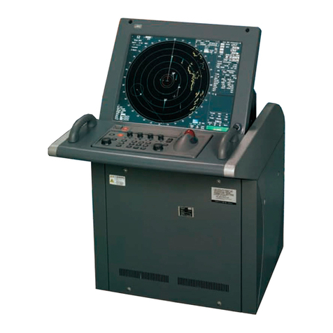
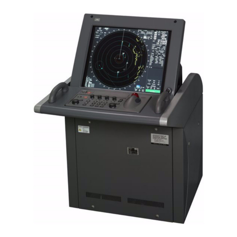
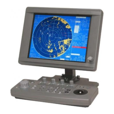
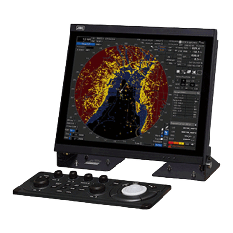
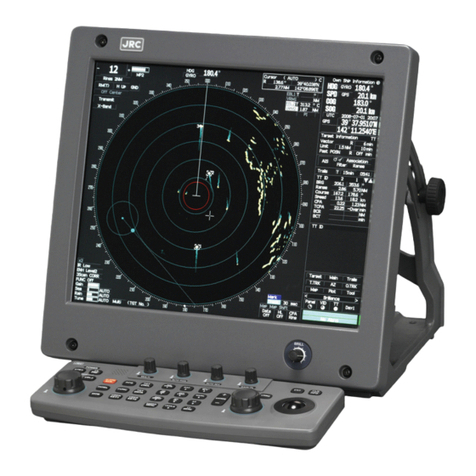
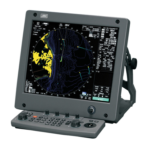
JRC JMA-5212-4/6 User manual

MARINE RADAR
MARINE RADAR
EQUIPMENT
EQUIPMENT
FIELD SERVICE
FIELD SERVICE
MANUAL
MANUAL
JMA-5212-4/6
JMA-5212-4/6
JMA-5222-7/9
JMA-5222-7/9
JMA-5212-4HS/6HS
JMA-5212-4HS/6HS
%1&'0Q<24&
1%6'FKVKQP,4%


Contents
Chapter 1_Equipment Overview
1.1. Overview ................................................................................................................................ 1-1
1.2. Scanner Unit .......................................................................................................................... 1-1
1.3. Display System ...................................................................................................................... 1-2
1.4. Principal Functions................................................................................................................. 1-2
Chapter 2_Equipment Overview
2.1. Configuration.......................................................................................................................... 2-1
2.1.1. Scanners and Transmitted Output Powers ..................................................................... 2-1
2.1.2. Radar Configuration and Ship's Mains............................................................................ 2-2
2.2. Power System Diagram ......................................................................................................... 2-4
2.3. Functional System Diagram ................................................................................................... 2-6
2.3.1. Scanner Unit ................................................................................................................... 2-6
2.3.2. Display System ............................................................................................................... 2-9
2.4. Input/Output Specifications .................................................................................................. 2-12
2.4.1. SCANNER (J2) ............................................................................................................. 2-12
2.4.2. GPS (J3) ....................................................................................................................... 2-13
2.4.3. GYRO/COMPASS (J5).................................................................................................. 2-13
2.4.4. AIS/NMEA (J6).............................................................................................................. 2-14
2.5. DIP-SW/Jumper Setting ....................................................................................................... 2-15
2.5.1. Power Circuit CBD-1702A............................................................................................. 2-15
2.5.2. GYRO I/F Circuit CMJ-304E ......................................................................................... 2-17
2.5.3. Radar Processing Circuit CDC-1350 ............................................................................ 2-20
2.5.4. AIS Processing Circuit CDC-1353 ................................................................................ 2-20
2.5.5. T/R Control Circuit CMC-1205R.................................................................................... 2-21
Chapter 3_Service Parts
3.1. Service Parts Lists for the Units ............................................................................................. 3-1
3.1.1. Spare Parts .....................................................................................................................3-1
3.1.2. Special Parts ...................................................................................................................3-2
3.1.3. NKE-2103 (JMA-5212-4/6/4HS/6HS).............................................................................. 3-2
3.1.4. NKE-2254 (JMA-5222-7/9).............................................................................................. 3-3
3.1.5. NCD-4380....................................................................................................................... 3-3

3.2. Exploded Diagrams................................................................................................................ 3-4
3.2.1. NKE-2103 ....................................................................................................................... 3-4
3.2.2. NKE-2254 ....................................................................................................................... 3-8
3.2.3. NDC-1460 ..................................................................................................................... 3-12
3.2.4. NCE-7699A................................................................................................................... 3-16
Chapter 4_Replacement of Major Units
4.1. Scanner Unit .......................................................................................................................... 4-1
4.1.1. Precautions for replacing parts in the scanner unit ......................................................... 4-1
4.1.2. Parts Replacement for the Scanner Unit NKE-2254 ....................................................... 4-2
4.1.3. Magnetron replacement / NKE-2254............................................................................... 4-3
4.1.4. Motor replacement / NKE-2254....................................................................................... 4-5
4.1.5. Motor drive circuit board replacement / NKE-2254 ......................................................... 4-7
4.1.6. Modulator circuit (CPA-264) replacement / NKE-2254.................................................... 4-8
4.1.7. Power supply circuit board (CBD-1682A) replacement / NKE-2254 ............................. 4-10
4.1.8. T/R control circuit (CMC-1205R) replacement / NKE-2254............................................4-11
4.1.9. Receiver (NRG-162A) replacement / NKE-2254........................................................... 4-13
4.1.10. Encoder replacement / NKE-2254 ................................................................................ 4-15
4.1.11. Magnetron fan replacement / NKE-2254....................................................................... 4-17
4.1.12. Modulator fan replacement / NKE-2254........................................................................ 4-18
4.1.13. NKE-2103 scanner unit parts replacement ................................................................... 4-21
4.1.14. Magnetron Replacement for the NKE-2103 .................................................................. 4-22
4.1.15. Motor Replacement for the NKE-2103 .......................................................................... 4-24
4.1.16. Motor Control Power Circuit Replacement for the NKE-2103 ....................................... 4-25
4.1.17. Modulation Circuit (CME-363) Replacement for the NKE-2103 .................................... 4-26
4.1.18. Power Circuit (CBD-1783) Replacement for the NKE-2103 .......................................... 4-27
4.1.19. Receiver (NRG-610) Replacement for the NKE-2103................................................... 4-28
4.1.20. Encoder Replacement for the NKE-2103...................................................................... 4-30
4.2. Display System .................................................................................................................... 4-32
4.2.1. Brilliance Control Circuit CCK-970 ................................................................................ 4-32
4.2.2. Power Supply Unit NBD-866A ...................................................................................... 4-34
4.2.3. Radar Processing Circuit CDC-1350 ............................................................................ 4-36
4.2.4. Battery .......................................................................................................................... 4-38
4.2.5. Target Tracking (TT) Unit NCA-877A ............................................................................ 4-40
4.2.6. AIS Processing Circuit NQA-2155 ................................................................................ 4-41
4.2.7. GYRO I/F Circuit CMJ-304E ......................................................................................... 4-43
4.2.8. GYRO I/F Circuit Fuses ................................................................................................ 4-45

4.2.9. Operation Circuit CCK-979 for the Standard Operation Unit......................................... 4-47
4.2.10. PS2 Connector Circuit CQC-1204 for the Standard Operation Unit .............................. 4-49
4.2.11. Trackball TRD-101S(BK)N1 for the Standard Operation Unit........................................ 4-51
Chapter 5_Program Update
5.1. Main Program Update Procedure........................................................................................... 5-1
5.1.1. Items to be Provided ....................................................................................................... 5-1
5.1.2. Update Procedure........................................................................................................... 5-1
5.2. AIS Processing Circuit Update Procedure ............................................................................. 5-2
5.2.1. Items to be Provided ....................................................................................................... 5-2
5.2.2. Update Procedure........................................................................................................... 5-2
5.3. How to Check the Version...................................................................................................... 5-3
Chapter 6_Troubleshooting
6.1. Operation Check .................................................................................................................... 6-1
6.1.1. Self-diagnostic Function (Self Test)................................................................................. 6-2
6.1.2. Display Unit Check (Monitor Test)................................................................................... 6-3
6.1.3. Operation Unit Check (Keyboard Test)............................................................................ 6-4
6.1.4. Performance Monitor (MON Display) .............................................................................. 6-5
6.1.5. System Alarm Log Display (Alarm List/Log) .................................................................... 6-5
6.1.6. System Information Display (System INFO).................................................................... 6-6
6.2. Error Message Lists ............................................................................................................... 6-7
6.2.1. Error Messages for the Scanner Unit.............................................................................. 6-7
6.2.2. Error Messages for the Display System........................................................................ 6-14
6.2.3. Error Messages for the External Input-Output Equipment ............................................ 6-19
6.3. Examples of Trouble ............................................................................................................ 6-31
6.3.1. Internal Circuits ............................................................................................................. 6-31
6.3.2. External Equipment....................................................................................................... 6-33
Chapter 7_Drawings
7.1. Outline Drawings.................................................................................................................... 7-1
7.1.1. Outline Drawing of the Scanner Unit NKE-2254-7 .......................................................... 7-2
7.1.2. Outline Drawing of the Scanner Unit NKE-2254-9 .......................................................... 7-3
7.1.3. Outline Drawing of the Scanner Unit NKE-2103-4/4HS .................................................. 7-4
7.1.4. Outline Drawing of the Scanner Unit NKE-2103-6/6HS .................................................. 7-5
7.1.5. Outline Drawing of the Display System NDC-1460 ......................................................... 7-6
7.1.6. Outline Drawing of the Display Unit NWZ-164 ................................................................ 7-7

7.1.7. Outline Drawing of the Operation Unit NCE-7699A ........................................................ 7-8
7.1.8. Outline Drawing of the Multi-function Operation Unit NCE-7729A .................................. 7-9
7.1.9. Outline Drawing of the Rectifier NBA-5111 (Option)...................................................... 7-10
7.2. System Diagrams..................................................................................................................7-11
7.2.1. Overall System Diagram of the Radar JMA-5222-7/9 ....................................................7-11
7.2.2. Overall System Diagram of the Radar JMA-5212-4/6/4HS/6HS ................................... 7-12
7.3. Inter-Unit Connection Diagram............................................................................................. 7-13
7.3.1. Inter-Unit Connection Diagram of the JMA-5222-7/9 .................................................... 7-13
7.3.2. Inter-Unit Connection Diagram of the JMA-5212-4/6/4HS/6HS .................................... 7-14
7.4. Unit Internal Connection Diagrams ...................................................................................... 7-15
7.4.1. Internal Connection Diagram of the Scanner Unit NKE-2254 ....................................... 7-15
7.4.2. Internal Connection Diagram of the Scanner Unit NKE-2103 ....................................... 7-16
7.4.3. Internal Connection Diagram of the Processor Unit NDC-1460 .................................... 7-17

Chapter 1
Equipment Overview


1-1
1.1. Overview
This equipment is marine radar equipment satisfying the IMO standard. The radar
equipment consists of a scanner unit that generates transmitting signals, transmits and
receives radio waves, and amplifies receiving signals, and a display system that displays
radar images after removing unwanted radio wave from the radar signals.
The radar equipment with which a magnetron tube is used as the transmitting tube
transmits 9.4 GHz (X band) pulse-modulated waves.
In addition to the basic radar functions, the radar equipment has functions for safe
navigation such as a radar trail display function, target tracking function*1, and AIS
information display function*1.
*1 The function is optional for radar equipment (not an IMO radar) which is designed for
fishing boats.
1.2. Scanner Unit
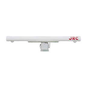
The scanner unit is an antenna that transmits a radar
signal into space, and sends the radar signal reflected
from a target into the equipment. The horizontal antenna
beam width is small for identifying the target bearing, and
the scanner unit has a rotating mechanism for detection in
the entire surrounding area.
Two types of scanner units are provided for this
equipment, and their usage is as follows:
ԘX band (10 kW) scanner unit: Compact and light
weight
ԙX band (25 kW) scanner unit: High resolution, and high sensitivity
Figure 1.2 X-25 kW scanner unit
Figure 1.1 X-10kW scanner unit

1-2
1.3. Display System
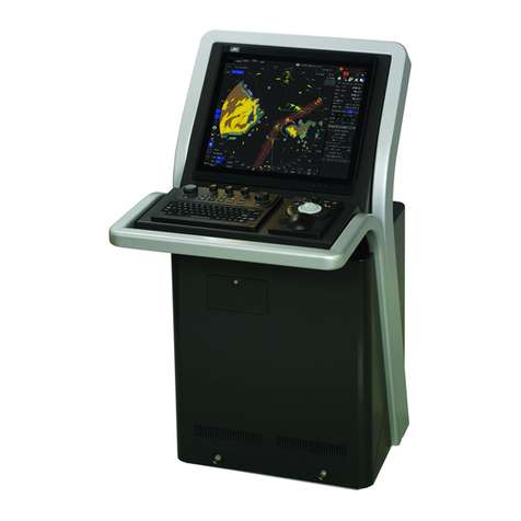
The display system processes a radar signal transmitted from the scanner unit, removes
unwanted radio wave, and plots/displays radar images in a specified observation range.
The user is to stand in front of the display system and observe the conditions around the
own ship with the radar images displayed on the display unit by operating the switches and
trackball on the operation unit.
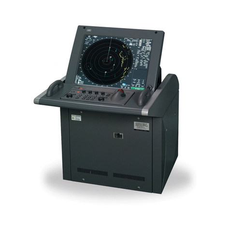
The display system consists of the following three units:
1.4. Principal Functions
This radar equipment satisfies the performance requirements defined in the IMO
standard MSC.192 (79) and has the following functions:
ԘSensitivity adjustment, and sea clutter and rain/snow clutter suppression
ԙInterference rejecter
ԚNavigation tools (cursor, VRM, EBL, and parallel cursor)
ԛOwn track display
ԜUser map creation and display
ԝRadar trail display
ԞTarget tracking*1
ԟAIS information display*1
ԠSelf-diagnostic function
ԡRadar performance monitoring (Performance Monitor)*1
*1 The function is optional for radar equipment (not an IMO radar) which is designed for
fishing boats.
Figure 1.4 Display unit (NWZ-164)
Operation unit (NCE-7699A)
Figure 1.3 Processor unit (NDC-1460)

Chapter 2
Equipment Overview


2-1
2.1. Configuration
2.1.1. Scanners and Transmitted Output Powers
IMO compliance
MODEL
NUMBER SCANNER TRANSMITTED
OUTPUT POWER BAND RATE OF
ROTATION CATEGORY
JMA-5212-4 4 FT SLOT ANTENNA 10kW X 27rpm CAT 2
JMA-5212-6 6 FT SLOT ANTENNA 10kW X 27rpm CAT 2
JMA-5222-7 7 FT SLOT ANTENNA 25kW X 24rpm CAT 2
JMA-5222-9 9 FT SLOT ANTENNA 25kW X 24rpm CAT 2
* Type of transmitted radio wave: P0N for all the models
Non IMO compliance
MODEL
NUMBER SCANNER TRANSMITTED
OUTPUT POWER BAND RATE OF
ROTATION
JMA-5212-4 4 FT SLOT ANTENNA 10kW X 27rpm
JMA-5212-6 6 FT SLOT ANTENNA 10kW X 27rpm
JMA-5222-7 7 FT SLOT ANTENNA 25kW X 24rpm
JMA-5222-9 9 FT SLOT ANTENNA 25kW X 24rpm
JMA-5212-4HS 4 FT SLOT ANTENNA 10kW X 48rpm
JMA-5212-6HS 6 FT SLOT ANTENNA 10kW X 48rpm

2-2
2.1.2. Radar Configuration and Ship's Mains
IMO compliance
MODEL
NUMBER
SCANNER PERFORMANCE
MONITOR UNIT
DISPLAY
SYSTEM
SHIP'S MAINS
JMA-5212-4 NKE-2103-4 NJU-85 NCD-4380 DC24V
JMA-5212-6 NKE-2103-6 NJU-85 NCD-4380 DC24V
JMA-5222-7 NKE-2254-7 NJU-85 NCD-4380 DC24V
JMA-5222-9 NKE-2254-9 NJU-85 NCD-4380 DC24V
Non IMO compliance
MODEL
NUMBER SCANNER PERFORMANCE
MONITOR UNIT
DISPLAY
SYSTEM SHIP'S MAINS
JMA-5212-4 NKE-2103-4 NJU-85 NCD-4380 DC24V
JMA-5212-6 NKE-2103-6 NJU-85 NCD-4380 DC24V
JMA-5222-7 NKE-2254-7 NJU-85 NCD-4380 DC24V
JMA-5222-9 NKE-2254-9 NJU-85 NCD-4380 DC24V
JMA-5212-4HS NKE-2103-4HS NJU-85 NCD-4380 DC24V
JMA-5212-6HS NKE-2103-6HS NJU-85 NCD-4380 DC24V

2-3
(Notes)
ԘA deicing mechanism (neck heater) is optional. "D" is suffixed to the model number
of a scanner unit with a deicing mechanism. Keep in mind that only power supply of
100-115 VAC, 50/60 Hz and single phase is applicable to the neck heater and that a
deicing mechanism cannot be installed in the NKE-2103.
ԙA scanner unit and display system are indicated on the nameplate of the equipment
as follows:
SCANNER UNIT
DISPLAY UNIT
ԚThe display system has a separate structure consisting of the following:
Display unit NWZ-164
Control unit NCM-866-E
The control unit NCM-866-E (IMO compliance) consists of the following:
Processor unit NDC-1460
Operation unit NCE-7699A

2-4
2.2. Power System Diagram
DC24V
+30%-10%
DC24V
+30%-10%
Processor NDC-1460
Filter
PWR
SENSE
P12V
±12V
AVR
PWR
CNT
Relay
+5V AVR
+3.3V
Poly-sw
Poly-sw
Filter
Filter
Motor
Motor
Control
AVR
System
Power
Supply
Scanner Unit NKE-2103/2254
NSK UNIT
NCT-4106A
(option)
Power SW
Keyboard Unit
NCE-7699A
15 inch LCD
NWZ-164
To GPS(6W)
0.5A
0.5A
Logic
Logic
4A
2A
Analog
Analog
PWR-O
+12V 1.0A
-12V 0.2A
F3
F2
Figure 2.1 Power System Diagram

2-5
Figure 2.1 shows the power system diagram of this equipment.
DC power passes through the circuit breaker via the line filter in the power circuit
CBD-1702A, and it is re-input to the power circuit CBD-1702A for generating the supply
voltage to be used inside the equipment. The power circuits are of the high-efficiency
switching type.
This equipment has an overvoltage protection function. If the input voltage exceeds
about 42 VDC, the power circuit CBD-1702A stops the output of the supply voltage to be
used inside the equipment; if the input voltage exceeds 50 VDC, it turns off the circuit
breaker, thus protecting the equipment from an overvoltage. The protective voltage is set
with the constant in the power circuit CBD-1702A.
The P+12V power supply is active even when the power switch on the operation unit is
turned off. This power supply is used with circuits such as the control circuits in the power
circuits.
When the power switch on the operation unit is turned on, the power supply to be used
inside the equipment is started, and the +5V, +3.3V, +12V, and -12V power supplies are
output for starting the equipment. The +5V and +3.3V power supplies are used mainly
with the ICs of control circuits. The +12V and -12V power supplies are used mainly with
external interface circuits.
The power output relay for the scanner unit operates in conjunction with the power switch
on the operation unit.
An overcurrent protection function is provided for each power output. If a load is
short-circuited or exceeds the rating, the protection function works to turn off the output.

2-6
2.3. Functional System Diagram
2.3.1. Scanner Unit
SLOT ANTENNA
MOTOR
B101
SAFETY SWITCH
S101
MAG
V101
PULSE
TRANS
SWITCHING
CIRCUIT
PC201
MH
GENERATOR
AVR
PC1001
㱂A,㱂B,㱂Z
FILTER
DUMMY
LOAD
DC+24V
Serial Com, BP, BZ, VD, TRIG
NKE-2254 Scanner Unit
POWER
SUPPLY
CIRCUIT
MOTOR CONTROL
POWER
PC1501
Rotation Control
Speed control
Status
DC+24V
Tx Trigger/Pulse Width
DC+24V
ENCODER
ROTARY
JOINT
INTERFACE CIRCUIT
PC1101
RF AMP
IF AMP
VIDEO
AMP
RECEIVER
Receiver
Bandwidth
Control
Tune Control
DIODE
LIMITER
Figure 2.2 Functional System Diagram of NKE-2254 Scanner Unit

2-7
Figure 2.2 shows the functional system diagram of the scanner unit for this equipment.
When the power relay for the scanner unit in the display system is turned on and power is
supplied to the scanner unit, the power circuit starts power supply to each circuit of the
scanner unit. The CPU in the interface circuit is started by starting the power supply, and
preheating of the magnetron is started after initialization. The scanner unit waits for a
communication signal from the display system. A communication link is established when
a communication signal is received, and then the scanner unit is placed under control of the
display system.
While the magnetron is being preheated, the interface circuit sets the operation of each
circuit of the scanner unit according to the initial setting value transmitted by the display
system. After completion of preheating, the scanner unit informs the display system that
the preheating is complete. When the operator performs operation to start transmission, a
transmission start command is sent through the communication line from the display
system, and the scanner unit starts the scanner motor and the transmission.
A transmission timing pulse is generated in the interface circuit and input to the modulator
switching circuit. After high-voltage switching for the modulator, the high-voltage pulse is
further boosted by the pulse transformer and applied to the magnetron for obtaining
pulse-modulated microwave. The radar-signal pulse width and repetition frequency are
specified by a control command from the display system.
The radar signal passes through the duplexer circuit configured with the circulator and
the rotary joint and transmitted into space from the antenna.
A signal reflected from a target is input through the antenna, and then input to the
receiving block by the duplexer function. After the received signal is amplified, it is
converted to IF frequency and log-detected, and turns into a radar video signal. If the
receiving tuning function is in automatic mode, the interface circuit processes the received
signal and automatically controls the tuning voltage to obtain optimum local frequency.
The motor power circuit controlled by the interface circuit is turned on, DC power is
supplied to the motor driver circuit, and the motor starts running. The rotation control
signal output by the interface circuit is supplied to the motor driver circuit after
frequency-voltage conversion in the motor power circuit, by which the motor speed is
controlled. When the safety switch is turned off, power supply to the motor driver is
forcibly turned off, by which the motor is stopped. The radiation bearing of scanner beam
is detected by the encoder.

2-8
The received radar video signal, transmission timing signal, and antenna rotation signal
are sent to the display system. The radar video signal is a non-processed, log-compressed
signal. The antenna rotation signal is an incremental signal, and 2048 rotation pulses and
reference bearing pulses per cycle are used.
When a specified time has passed during the stopping of the communication signal from
the display system, the interface circuit moves into the protection mode, and forcibly stops
the transmission and the scanner unit.
Other manuals for JMA-5212-4/6
1
This manual suits for next models
8
Table of contents
Other JRC Marine Radar manuals

JRC
JRC JMR-7296-6X User manual

JRC
JRC JMA-9110-6XA User manual

JRC
JRC JMR-5410-6X User manual

JRC
JRC JMA-5208HS User manual

JRC
JRC JMA-5104 User manual

JRC
JRC JMA-7133-SA User manual

JRC
JRC JMA-7710-6 User manual

JRC
JRC JMR-7230-S3 User manual

JRC
JRC JMA-5352-9R User manual

JRC
JRC JMA-1030 Series User manual

JRC
JRC 2000 Quick start guide

JRC
JRC JMA-7110-6XA User manual

JRC
JRC JMA-1032 User manual

JRC
JRC JMA-9133-SA User manual

JRC
JRC JMA-3806 User manual

JRC
JRC RADAR 1800 User manual

JRC
JRC JMA-5312-6/6HS User manual

JRC
JRC JMR-5406-X User manual

JRC
JRC JUE-250 - Operator's manual

JRC
JRC JMA-5312-6HS User manual