Safety
1.3.2 Warning of property damage
WARNING
Risk of water damage or damage
to property
The device may only be installed by
qualified technical personnel.
The installation room must be dry and
free from frost.
The ambient temperature must not
exceed 30 °C! In higher temperatures
or direct sunlight, material damage may
occur up to and including breakage of
device parts.
An adequately sized waste water con-
nection (e.g. floor drain) in compliance
with DIN 1986 must be provided.
In order to ensure safe drinking water
hygiene, a free discharge of the waste
water acc. to DIN EN 1717 must be
ensured.
The pipe must be able to safely sup-
port the device (weight: see chapter 7).
If necessary, the pipes must be provided
with additional fastenings or support.
If no bypass valve is installed, a shut-
off valve must be installed upstream of
the unit in order to interrupt the water
supply during installation, maintenance,
repair or malfunction of the device.
Install the device in a vertical position
(± 5°). Otherwise, water may escape and
cause water damage.
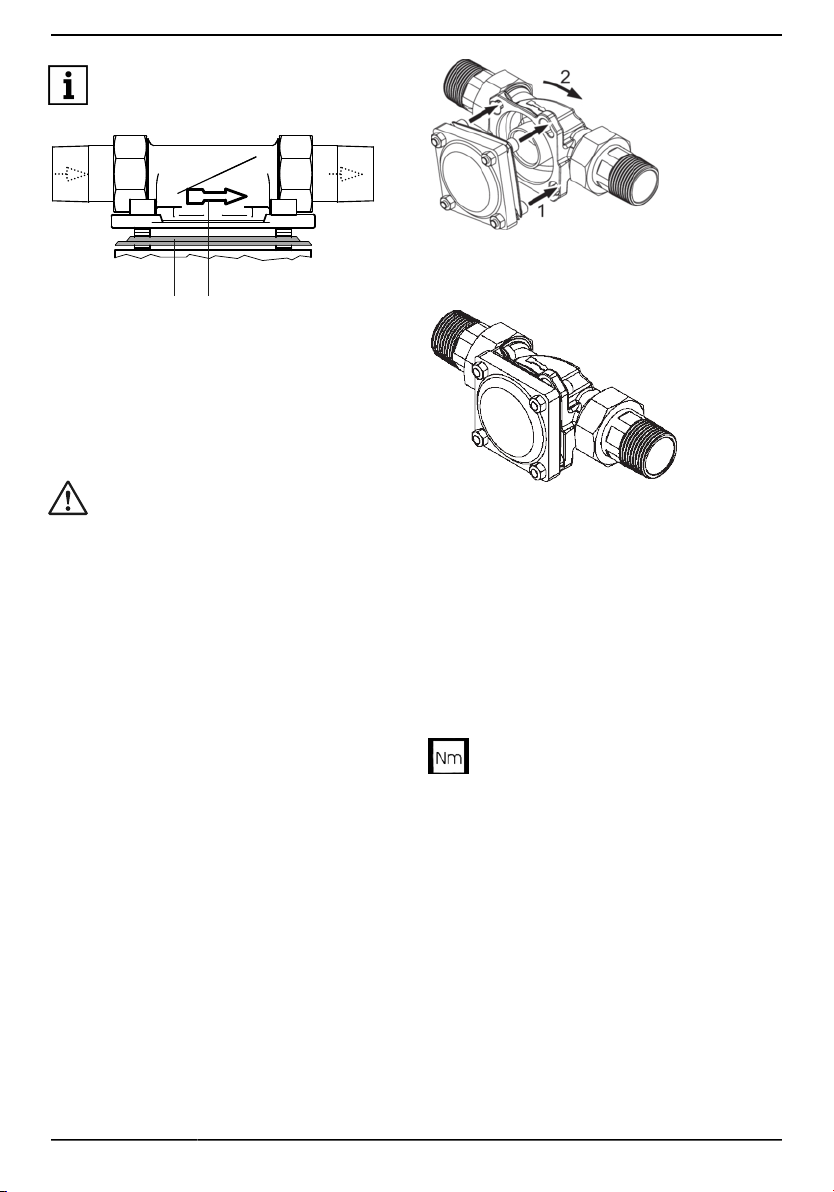
For the installation of the device in
domestic water piping, only use the sup-
plied built-in rotary flange (see chapter
3.2).
The flange surface of the rotary flange
fitting must be upright!
The rotary flange fitting must be fitted so
that it is free from mechanical stress or
strain. Otherwise mechanical damage to
the pipe or the rotary flange fitting up to
and including breaks can result.
For proper sealing the profile of the pro-
file flange seal must point towards the
rotary flange fitting (see Figure 3).
Only operate the device in a technically
faultless condition:
•Check for damage prior to installa-
tion.
•Immediately have any malfunctions in
operation rectified by qualified tech-
nical personnel.
Persons who, due to their physical, sen-
sory or mental abilities or their inexperi-
ence or lack of knowledge, are unable to
operate the device safely may not oper-
ate it without supervision or instruction
from a responsible person.
Regular backwashing of the device is
required to ensure safe drinking water
hygiene (see chapter 4.2.1).
Before carrying out a backwash, ensure
that the wastewater connection is func-
tional.
At the end of the backwashing process,
turn the handwheel until it engages so
that no more backwash water escapes.
Otherwise, water may constantly escape
and cause water damage.
Do not use household cleaning agents
to clean the outside of the device, but
only use clear water to avoid embrittle-
ment of the plastic.
The device may only be repaired by
qualified technical personnel.
Only use original spare parts for repairs.
Before performing work on the device
that goes beyond pure operational use,
the device must be depressurised! If
this is ignored, the result may be uncon-
trolled escape of water resulting in water
damage to the building/home.
1703301 • 2020/07 JUDO JPM-QC 5