JuiceGoose RX Series User manual

OWNER’S
MANUAL
CQ SERIES
SEQUENCED POWER CONTROL
CQ-1515TM, CQ-1520TM,
CQ-1TM, CQ-50TM, CQ-2200TM,
CQ-3000TM and CQ-PD1-4TM
includes
CQ-1515-RXTM and CQ-1520-RXTM
2023
File: 3176209DEN-001
Standard: UL508

DISCLAIMER
Juice Goose shall under no circumstances be held responsible for any losses, damage, or injury re-
sulting directly or indirectly from the use of a CQ Series device in a manner contrary to accepted
safe operating methods or any instructions contained in this document. The user should determine
prior to use whether this product is adequate, suitable and safe for the application intended. Since
individual applications can be subject to extreme variation Juice Goose makes no representation or
guarantee as to the suitability of a CQ product for any generally described application.

CQ-SERIES
SEQUENCED POWER CONTROL SYSTEM
The Juice Goose CQ Series products are power distribution devices that will control AC power appli-
cation to multiple pieces of equipment. The primary intent of the design of this equipment is to power
rack mounted audio or video equipment with electric power current requirements of less than 15
amps, 20 amps or 30 amps depending on the CQ model being considered.
All CQ Series products can be remote activated. Several CQ devices can be connected to form a
power sequencing system that includes multiple circuits in multiple locations.
SAFETY PRECAUTIONS
CQ Series products are designed to operate at 120 volts, 60 hertz. Operation with any voltage or fre-
quency other than that can damage the equipment and create an unsafe situation.
CAUTION #1: All CQ devices must be grounded. If a power extension cord is required, use a prop-
erly insulated and grounded cord. Failure to ground the device could expose the user to dangerous
electric shock.
CAUTION #2: All CQ devices should be installed only by qualified electrical technicians using appro-
priate mounting hardware and correct installation techniques. When installing make sure main power
is off before attaching the CQ device. There are no user serviceable parts inside any of the CQ prod-
ucts.
CAUTION #3: Do not expose the CQ product to moisture or salty air. Doing so could cause signifi-
cant damage and create an unsafe condition.
PRÉCAUTIONS DE SÉCURITÉ
Série CQ produits sont conçus pour fonctionner à 120 volts, 60 hertz. Fonctionnement avec une ten-
sion ou une fréquence autre que celle qui peut endommager l'équipement et de créer une situation
dangereuse.
ATTENTION #1 : CQ tous les périphériques doivent être mis à la terre. Si une extension de cordon
est nécessaire, utiliser un correctement isolés et cordon mis à la terre. Échec à la masse le périphéri-
que pourrait exposer l'utilisateur à choc électrique.
ATTENTION #2 : Tous les périphériques CQ ne devrait être installé que par des électriciens qualifiés
avec matériel de montage approprié et correct techniques d'installation. Lors de l'installation assurez-
vous que l'alimentation principale est hors tension avant de procéder à l'accrochage de la CQ
périphérique. Il n'y a aucune pièce réparable par l'utilisateur à l'intérieur des CQ produits.
ATTENTION #3 : Ne pas exposer le CQ produit de l'humidité ou air salé. Cela pourrait causer des
dommages importants et créer une situation dangereuse.

DETAIL SPECIFICATIONS
DIMENSIONS (H x W x D inches)
CQ 1515 & CQ 1520……..………………….……………..….....….....………...1.72 x 19.00 x 7.00
CQ 1(Including 3 Gang Utility Box)..................................................................4.50 x 6.50 x 3.75
CQ 50…………………………………………………………………………………...9.5 x 9.5 x 1.75
CQ 2200 ................……………….......................………………………..………5.50 x 6.40 x 3.75
CQ 3000...........................................................................................................9.00 x 6.00 x 4.00
CQ PD1-4.…..…………………………………………….....…………..………...32.00 x 3.50 x 2.00
WEIGHT (lbs)
CQ 1515 & CQ 1520….…………..………………………….................................……………..10.0
CQ 1.........................................................................................................................................1.0
CQ 50….…………………………………………………………………………………..…………...5.0
CQ 2200 ................…………………………....…………………....................……………………4.0
CQ 3000...................................................................................................................................6.0
CQ PD1-4……………………………………..................................................................……...15.0
CIRCUIT BREAKER
CQ 1515...............................................................................................Back Panel, 15A Thermal
CQ 1520………………………………………………........……………....Back Panel, 20A Thermal
CQ 1.....................................................................................................................................None
CQ 50………………………………………………………………………..Back Panel, 15A Thermal
CQ 2200………………................………………………..…….…..……...Side Panel, 20A Thermal
CQ 3000………………………......………………………….……….…….Side Panel, 30A Thermal
CQ PD1-4………………………………..…………………….………………...………………….None
POWER INPUT
CQ1515……….........………..………….....…Power Cord, 7 Foot, 14/3 SJTW with NEMA 5/15P
CQ1520……….........………..………….....…Power Cord, 7 Foot, 12/3 SJTW with NEMA 5/20P
CQ 1.........................................................Hardwire, Insulated Three Wire Connection (H, N, G)
CQ 50.………………………………...Detachable Power Cord, 6 Foot, IEC C13 to NEMA 5/15P
CQ 2200 .……….............................................…...Hardwire with Crimp Tight Fast-on Terminals
CQ 3000...........................................................................................Hardwire to Screw Terminal
CQ PD1-4………………...................................…………Hardwire with External 4’ Wire Harness
VOLTAGE INPUT.……………………….……….………………...……………...120 VAC at 60 Hz
POWER OUTPUTS
CQ 1515.…,,…..........….…....Six NEMA 5/15R Sequenced and One NEMA 5/15R Unswitched
CQ 1520.…,,…..........….…....Six NEMA 5/20R Sequenced and One NEMA 5/15R Unswitched
CQ 1...............................................................................................................Two, NEMA 5/15R
CQ 50………………….……….Two NEMA 5/15R Switched and One NEMA 5/15R Unswitched
CQ 2200…………………..……………………………….......…….Four NEMA 5/20R, Sequenced
CQ 3000.…..............................................................................................…..One NEMA L5/30R
CQ PD1-4..………………….……….………………………...…...Eight NEMA 5/20R, Sequenced
NUMBER OF SEQUENCE EVENTS
CQ 1515 & CQ 1520..………………………………………………….....Three (Timing adjustable)
CQ 1.…………………………….......………….….…………………………………...…………..One
CQ 50………………………………………………………………………………………...……...One
CQ 2200……………………………….……….….………...………………Two (Two second delay)
CQ 3000……………………………….……….….………………………………………………...One
CQ PD1-4……………………………….…….….………………...……….Four (Two second delay)
POWER PROTECTION
CQ 1515 & CQ 1520………………….……….….Triple MOV Matrix. No ground line connection
CQ 1515-RX & CQ 1520-RX………...See “RX Series Surge Protection” section of this manual
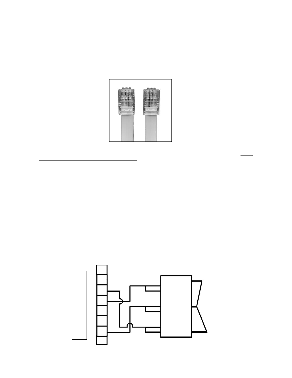
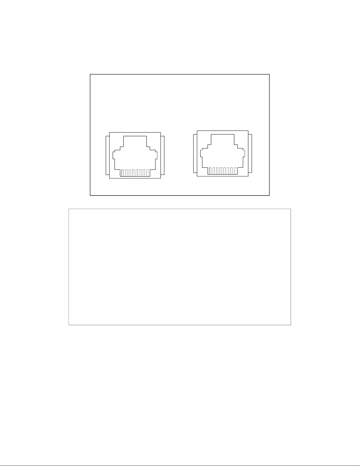
COMMUNICATIONS LINE…............................……RJ-45 (See Owners Manual for Assembly)
STATUS MONITORING LED (CQ 1515 & CQ 1520)
POD 1,2,3………………………………………………….……………...Indicates power activation
PROCESSOR (“PROC”)
Blue/Red Blinking…………….……...Sequencer and surge protection are functioning
Blinking Red…………………….…………………………..….…...Surge protection fault
Solid Blue or Off……………………………………………………...…...Sequencer fault

MOUNTING AND PLUG IN
CQ 1515 & CQ 1520 — Mount the CQ-1515 or CQ-1520 to a 19” wide rack with metal mounting rails. Use ap-
propriate rack mounting hardware. Plug the power cord into a grounded outlet. Do not defeat the grounding
feature of the power cord.
CQ 50 - This product can be mounted to a flat, stable surface using four holes on the two mounting side
flanges. Be sure to place the product near an AC receptacle and to leave room for connection of the CQ control
cable(s). Plug the cord into a grounded outlet. Do not defeat the grounding feature of the power cord.
HARD WIRED INSTALLATION
These products were designed to be installed only by qualified electrical technicians. Failure to follow correct
installation techniques and instructions could result in equipment damage and/or personal injury. CAUTION: Be
certain power has been turned off at the breaker panel or disconnected before installation. (ATTENTION: cer-
tains power a été désactivé sur le panneau de disjoncteur ou déconnecté avant l'installation.)
CQ 1 - This product should be installed in a three gang utility box mounted inside a wall. The installation process
may vary depending on whether the installation is in new or retrofit construction. Fit the utility box into the space
where the CQ 1 will be installed. Pull the main power cable and the RJ45 signal cable(s) into position inside the
utility box. Connect the power feed to the corresponding colored wires on the CQ 1 using wire nuts or another
acceptable method. Plug the input signal cable into the Input port on the CQ1 and the output cable into the Out-
put port. Install the CQ 1 enclosure and cover plate onto the utility box with the screws provided with the unit.
CQ 2200 & CQ 3000 are intended to be hardwired to a main utility power supply with power cable routed
through conduit. A “squeeze” type conduit connector is assembled onto the CQ back box specifically for this
purpose. A power line strain relief is also included in the box with the CQ device in case alternate power connec-
tion is necessary.
These two CQ Series models have front panel and a back box construction that are held together with seven
screws. To begin installation, remove the screws that hold these two pieces together. The back box has four
holes in the back surface. These holes are large enough to accommodate mounting screws or bolts (not in-
cluded) to hold the CQ device securely to a stable, flat mounting surface, such as a wall. At least two screws or
bolts should be used to mount the back box.
After the back box is secured, feed the cable that is connected to the desired power source through the hole in
the side of the back box. CQ2200: Securely crimp a connector (provided) to the end of each wire lead (hot,
neutral and ground). Press the connectors onto the appropriate locations on the circuit board as labeled.
CQ3000: Connect each wire lead to the appropriate position on the terminal block and tighten securely. Attach
the front panel (containing the circuit board) to the back box using all seven screws. Gently pull excess power
cable out of the box by tugging slightly on the cable from the outside of the box. Insert conduit into squeeze con-
nector and tighten the connector to hold the conduit in place.
CQ-PD1-4 - The CQ-PD1-4 has two slotted side brackets that can be relocated along the length of the chassis.
Use only appropriate hardware (not included) and use four mounting holes to secure the device. The wire har-
ness should be connected directly to a circuit breaker panel or to an appropriate junction box.

SIGNAL CABLE ASSEMBLY
The interconnecting CQ Series devices requires eight wire, RJ-45 cable. While this is the same component used
to assemble CAT5 and CAT6 cables, orientation of the connectors on the CQ Series cable is slightly different
than for the CAT data networking cable. Standard CAT5 or CAT6 cables will not work with CQ Series de-
vices.
After crimping a RJ45 connector on one end of the eight wire cable, attach a connector on the other end with
reversed orientation from the first so Pin 1 is on the opposite side of the cable from the first connector. Check
the cable with a continuity tester prior to installation.
There is no known distance limit for the connection of CQ units by means of this cable system.
REMOTE SWITCH CONNECTION
Single Pole Double Throw
Latching Switch or Relay
Although a Juice Goose CQ Series product can be remote controlled with a Juice Goose RC-5 accessory or
another CQ device, it can also be remote activated with a simple contact closure using a switch or relay. The
following instructions are provided to assist with this configuration.
In the illustration below, connecting a single pole, double throw (SPDT) switch to the signal input line of a CQ
Series device will control the sequence up and down activity. Closing Pin 3 to Pin 7 will begin a sequence UP.
Closing Pin 4 to Pin 7 will begin a sequence DOWN. Closing both 3 and 4 to 7 will PAUSE the sequence proc-
ess. When one of these contacts is made the sequence control switch on the chassis will be inoperative. The
Manual Override switch will still function.
8 7 6 5 4 3 2 1
1 2 3 4 5 6 7 8
C
Q
I
N
P
U
T
1
2
3
4
5
6
7
8

8 7 6 5 4 3 2 1 1 2 3 4 5 6 7 8
PIN ASSIGNMENTS
The chart above shows assigned locations for each of the eight pins on the
RJ45 connectors on the CQ Series Signal Input and Output. Note: although
there are eight pins, only the middle six are being used.
This information may be used to connect a latching contact, as per the dia-
gram on the previous page. It also illustrates the reversed orientation of the
connectors on each end of a CQ signal cable.
Pin assignments are correct when viewed from the outside of the chassis.
Signal
Input
Signal
Output
CQ Series
Signal Cable Connectors

OPERATION
These versatile CQ devices can be controlled by way of either another CQ device, a remote latching contact
closure, a Juice Goose RC5 accessory unit or the switch on the CQ device itself (except CQ 1, CQ5 and CQ50).
CQ DEVICES - Any CQ device can operate in concert with others. Each can be a master (except CQ1, CQ5 or
CQ50) or slave unit. Any number of CQ devices can be connected in a daisy chain fashion to operate as a
power sequencing system.
REMOTE CONTACT CLOSURE - As one option, to control the sequencing function, the Signal Input for the first
CQ device can be connected to a latching contact closure (see previous section “Remote Switch Connection”).
Juice Goose recommends use of a double throw device in order to maintain one of two contact closures at all
times. AV control devices such as those produced by Crestron may have relay cards that can serve this func-
tion.
RC-5 REMOTE ACCESSORY - Juice Goose offers, as an accessory, the RC-5 Remote Control/Monitor. These
devices provide sequence control as well as indicators to show the status of the power sequencing operation.
The RC-5 connects directly to the Signal Input of the first CQ device.
SEQUENCE SWITCH (Not including the CQ 1, CQ5 or CQ50) - Without a contact closure on the Signal Input,
the switch on the CQ device will control its operation. Switches on the CQ 2200, CQ 3000 and CQ PD1-4 have
three positions: Sequence up, Sequence Down and Manual On. If the product in question is not a slave in the
CQ network, the Sequence Up and Down positions will activate the sequence process for that CQ unit and
cause it to activate any units connected to its Signal Output. In the event of a failure of a particular CQ unit, the
Manual On switch position allows activation of the CQ device. (Note: the Manual On option does not provide
sequencing). The CQ 1515 and CQ1520 have a two position sequence switch and a second, recessed Manual
On switch on the front panel of the chassis.
MONITORING
Some CQ Series devices have a number of LEDs on the chassis to allow real time monitoring of the device’s
operation. The LED labeled “PROC” indicates the control program is running. That LED blinks blue and red un-
der normal conditions. Blinking red indicates a fault with the surge protection circuitry. Solid blue or off indicates
a fault with the sequence control circuitry. “POD” LEDs light to indicate activation of power to a corresponding
group of power outlets, indicating a sequence stage has been completed and the corresponding POD has
power.
Juice Goose offers RC-5 remote control and monitor accessories that provide indications of sequence operation
and completion. For more information about the RC-5, contact your Juice Goose dealer, refer to the Juice
Goose product catalog or visit www.juicegoose.com.
RX SERIES SURGE PROTECTION
CQ 1515-RX and CQ 1520-RX feature high level power line protection. This RX power protection technology is
particularly valuable because it works against common mode (ground line) as well as normal mode (line to neu-
tral) events. While it protects against dramatic surge events of up to 6,000 volts at 3,000 amps on hot and neu-
tral, it also limits ground line surges to one-half (0.50) volt to prevent operating faults of digital processing equip-
ment. Power protection circuitry in the CQ Series-RX includes a differential transformer, series inductor, high
levels of filtering capacitance and control circuitry providing protection from dangerous surges, high frequency
interference, building wiring faults and over voltage.
AC Power Filtration @ 30 MHz…………………………………….…...….80dB Common Mode, 60dB Normal Mode
Transient Energy Absorption…………………………….…………………………...……………………….1,020 Joules
Max AC Surge Let Through……………………………....10 Volts Normal Mode, 1/2 Volt Common Mode (Ground)
External Fault Protection……………………………………….....Open Ground, Hot-Neutral Reversal, High Voltage

ADJUSTING SEQUENCE DELAY TIMING
There are three sequence events on the CQ1515 and CQ1520. (See also CQ1515-RX and CQ1520-RX). The
standard factory delay is 2 seconds between each sequence event. That timing can be adjusted. Note: Only the
CQ15xx models have field adjustable timing. Contact Juice Goose is a sequence delay adjustment is required
on any other CQ Series model.
Optional settings are 10 seconds, 20 seconds and 30 seconds. Changing the timing will only affect the product
to which the adjustment is made and will not change the timing of any other CQ Series products connected by
control lines.
Adjusting the delay time requires removing the top of the CQ15xx chassis and accessing a small “dip switch”
located on the main circuit board.
WARNING: Always ensure the unit is powered down and unplugged before attempting this procedure.
Step 1. Remove the chassis top
The chassis top is held in place by six screws (three at the top of each side). Remove all six and remove the top.
Leave the bottom screws in place.
Step 2. Locate the dip switch on the main board and move to desired position
Step 3. Replace the chassis top and test
Return the top to the main chassis and fasten securely with the six top assembly screws. Plug the unit in and
test the delay. If the delay is not as expected, repeat steps 1 through 3 and ensure the dip switches are fully
pushed into the correct positions.

IN CASE OF MALFUNCTION
The Juice Goose CQ Series of products are ruggedly constructed and contain quality components.
There are no user serviceable parts inside a CQ device. Unauthorized service will void all existing
warranties and may result in equipment damage and personal injury.
Should improper performance be observed consult the following guidelines for diagnosis.
SYMPTOMS AND SOLUTIONS.
(NOTE: References to LEDs and circuit breakers do not apply to the CQ-1 and CQ-PD1-4)
1. Unit will not turn on.
a. Check to see that main utility power is available.
b. Check that the circuit breaker on the CQ unit is not tripped.
c. Check the Processor LED on the chassis. If it is not lit the CQ device is probably not re-
ceiving power. If it is lit but not flashing the CQ processor is not running. Remove power from the CQ
device by unplugging it or turning off the circuit breaker that feeds the unit. Then restore power to
reset the CQ processor.
d. If the device is being remotely activated:
i. Check the signal line leading to the CQ signal input. Disconnect the signal input
cable and try to activate the CQ product with the switch on the chassis. If this works either the cable
is bad or the control device intended to remote control the CQ in question is failing to create the cor-
rect contact closure. If possible, exchange the cable in question with a known good cable. If this does
not solve the problem examine the remote activation device and its connections to the cable.
ii. Refer to the manual’s Signal Cable Assembly and Remote Switch Connection sec-
tions.
iii. If the CQ device is being operated by another CQ unit check that controlling unit.
Is the controlling unit operating properly? Is its Processor (“PROC”) LED flashing?
2. Unit will not turn off.
a. It is likely that when a unit fails to turn off the cause is similar to that which would cause a
unit to fail to turn on.
b. Follow steps outline in 1 c. and d., above.
c. Once a system of interconnected CQ devices is turned on, a specific CQ device will not
turn off if the device following it in the turn-on sequence is still on. Check the CQ device following the
CQ device in question. Has it turned off properly? If not, check all the following units to the end of the
CQ system. Follow the steps in 1., above regarding the last unit that is misperforming.
3. Unit turns itself off unexpectedly.
a. The unit may have encountered excessive current draw that caused the circuit breaker to
trip. Examine the breaker. If it has tripped, the button section of the breaker will be extended and can
be reset by pushing it in after the unit has been off for a brief period.
b. Review the current requirement of the equipment plugged into the CQ device and com-
pare it to the amperage rating of the CQ device in question. See the Detail Specification section of
this manual.
If the problem can not be remedied or if the encountered problem is not listed here and particu-
larly if any evidence of severe or hazardous performance is observed, immediately discon-
nect power to the CQ device and contact your local Juice Goose dealer or Juice Goose di-
rectly.
SERVICE
Should your unit require service, contact Juice Goose to receive a service authorization
number. This number will allow us to track your returned unit. Please note that no returns
will be accepted without such a number.
7320 Ashcroft, Suite 104
Houston, Texas 77081
(p) 713-772-1404
(e) info@juicegoose.com

OTHER JUICE GOOSE PRODUCTS
RACK MOUNTED POWER DISTRIBUTION - JG Series and RP Series horizontal power
distribution with several optional features.
AC LINE SURGE PROTECTION - The Juice Goose RX Series technology provides very
high levels of protection against damaging power surges and high frequency interference on
hot, neutral and ground. RX Series protection is available as an optional feature in the CQ,
IP Series models.
WEB BASED CONTROL POWER - When Ethernet or RS232 power control is required,
Juice Goose offers the iP Series of remote control power distribution products. These de-
vices feature an on board web server as well as TCP or UDP communications links.
CUSTOM MULTIPLE CIRCUIT POWER DISTRIBUTION - When the components in a sin-
gle rack demand multiples of twenty or thirty amp circuits Juice Goose provides a custom
assembled power distribution product. The PD Series is configured by Juice Goose to the
specified requirements of each individual installation. A wide variety of features is available.
UPS (Battery Back Up) - Juice Goose sells high quality, value priced battery back up prod-
ucts to provide clean AC power and battery support in the event of a black out. Sizes range
from 350 VA to 3,000 VA, in either line interactive (voltage regulating) or on-line designs.
Since 1983
This manual suits for next models
10
Table of contents
Other JuiceGoose Surge Protector manuals
Popular Surge Protector manuals by other brands

KUSSMAUL
KUSSMAUL 091-98-12 installation instructions

THOMSON
THOMSON SpikeMaster Series user guide

PS Audio
PS Audio Ultimate Outlet Operation manual

Cornelius
Cornelius 230 VAC installation instructions

Monster Power
Monster Power POWERCENTER HTFS1000 owner's manual

urmet domus
urmet domus 1382/80 quick start guide