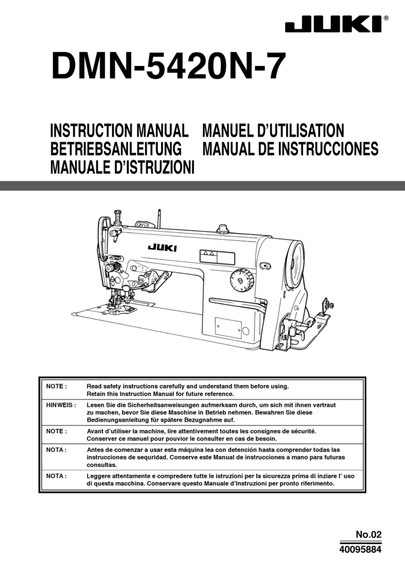
JUKI AK118 User manual

INSTRUCTION MANUAL / PARTS LIST
AK118
自動押え上げ装置(窓板取り付けタイプ)
Auto-lifter(Side-plate-mounting type)
Read safety instructions carefully and understand them before using.
Retain this Instruction Manual for future reference.
CAUTION
This Instruction Manual is intended for the AK118. Read and fully understand the
instructions given under “IMPORTANT SAFETY INSTRUCTIONS” in the Instruction
Manual the DDL-9000 or DLN-9010/9010A before putting the machine into service when
this device is installed to the DDL-9000 or DLN-9010/9010A .
In addition, to emphasize the AK118, some illustrations of the DDL-9000 or DLN-
9010/9010A are simplied. Also, illustrations of the safety devices are partially omitted.
No.04
29327905

目 次
CONTENTS
1. INSTALLATION ................................................................................................................. 1
2. HOW TO SELECT THE FUNCTION OF AUTO-LIFTER................................................... 5
3. HOW TO SELECT THE FUNCTION OF LIFTING THE PRESSER FOOT
AUTOMATICALLY AFTER THREAD TRIMMING ............................................................. 7
4. SPECIFICATIONS ............................................................................................................. 7
5. PARTS LIST....................................................................................................................... 8

– 1 –
1) ミシンの窓板を取り外し、ひざ上げ横棒の段
ねじを外します。
1) Remove the side plate of the machine, and remove
hinge screw in knee lifter side rod .
WARNING :
Turn OFF the power before starting the work so as to prevent accidents caused by abrupt start of the
sewing machine.
INSTALLATION
In case of DDL-9000
2) ひざ上げリンクの段ねじを外し、付属のば
ねをセットしたひざ上げリンクと交換し、
段ねじで取り付けます。
この時、ミシンを倒してひざ上げ連結棒が連
結棒ガイドの穴に入っていることを確認して
ください。
2) Remove hinge screw in knee lifter link , and
replace it with knee lifter link set with attached
spring . Then install the knee lifter link with hinge
screw .
At this time, tilt the machine and make sure that
knee lifter connecting rod enters the hole of
connecting rod guide .
3) 交換したひざ上げリンクに、ひざ上げ横棒ピ
ンをねじ締めし、ひざ上げ横棒をピンで
取り付けます。
3) Tighten with screw knee lifter side rod pin to
replaced knee lifter link , and install knee lifter
side rod with pin .
(Caution) 1. Securely tighten knee lifter side rod
pin since it is easily loosened.
2. Apply grease to the hinge sections of
respective hinge screws.

– 2 –
4) 糸ゆるめワイヤーと給油パイプを押さえる
ように、ひざ上げリンクばね掛けをワイヤー
押え台に取り付けます。この時、給油パイプ
と糸ゆるめワイヤーの経路にご注意くださ
い。
5) ひざ上げリンクばね掛けの切り欠き部にひざ
上げリンクばねを掛けます。
4) Install knee lifter link spring hook on wire pressing
base so as to hold down thread release wire
and oil tube . At this time, be careful about routing
of oil tube and thread release wire .
5) Place knee lifter link spring on the notch of knee
lifter link spring hook .
Notch
In case of DLN-9010/9010A
Notch
1) ミシンの窓板を取り外します。
2 )
ひざ上げリンク
の段ねじ
を外し、付属のばね
をセットし、段ねじ
を締め付け直します。
3 )
ひざ上げリンク
に、付属のひざ上げ横棒ピン
を取り付けます。
1) Remove the side plate of the machine.
2) Remove hinge screw in knee lifter link , and
set attached spring . Then tighten again hinge
screw .
3) Install attached knee lifter side rod pin in knee
lifter link .
4 )
頭部に取り付けられているワイヤー押え台
の切
り欠き部に、ひざ上げリンクばね
を掛けます。
4) Place knee lifter link spring on the notch of wire
pressing base which is installed on the machine
head.
※
DLN-9010/9010A の場合、下記の部品は使
用しません。
・GAKA1840000 ひざ上げリンクばね掛け
・GAKA1841000 ひざ上げリンク
・GAK330400A0 ひざ上げ横棒ピン ( 組 )
(1 ヶのみ )
・SS4110715SP 止めねじ
・GAKA1843000 ひざ上げリンク支点軸
*In case of DLN-9010/9010A, the spare parts below
are not used.
• GAKA1840000 Knee lifter link spring hook
• GAKA1841000 Knee lifter link
• GAK330400A0
Knee lifter side rod pin (asm.) (Only one)
• SS4110715SP Screw
• GAKA1843000 Knee lifter link fulcrum shaft

– 3 –
Slot
Apply grease
From here, the installation procedure is common to DDL-9000 and DLN-9010/9010A.
6 )
AK 装置(組)
をミシンに取り付けます。この時、
ひざ上げ横棒ピン
にソレノイドリンク
の長穴
がセットされるように取り付けます。
6) Install AK device (asm.) on the machine. At this
time, install the device so that the slot of solenoid
link is set on knee lifter side rod pin .
(Caution) Apply grease to the slot of solenoid link
.
7) AK 装置(組)のコードをテーブルの穴に通し、
2P コネクタをコントロール基板上の 2P コ
ネクタ(2P 白 CN9)に差し込みます。
7) Pass the cord of AK device (asm.) to the hole in
the table, and connect 2P plug to 2P connector (
2P white CN9 ) on the control circuit board.
8) 付属のコードバンドで、他のコードと束ねてく
ださい。
8) Bundle the cord with other cords using the attached
cord band.
Setup of SC-920

– 4 –
9) ミシンの面板を外して押えを下げ、引き上げ板
を下方に押し下げた状態にして、ドライバー
でソレノイド軸を左側に回転させ、六角棒
スパナ で抱きねじを締めます。この時、ソ
レノイドは矢印の方向へ押し付けた状態でセッ
トします。
9) Remove the face plate of the machine, put lifting
lever in the state of pressing down, turn solenoid
shaft to the left with screwdriver , and tighten
screw with hexagonal spanner . At this time,
set the solenoid in the state that it is pressed in the
direction of the arrow.
(Caution) In the state that the presser foot comes
in close contact with the throat plate,
make sure that a clearance is provided
between the back face of presser bar
guide bracket and lifting lever .
10) AK 装置を使用する場合は、テーブルの頭部支え
棒を取り外してご使用ください。
10)Remove the head support bar on the table when
using AK device.
Clearance

– 5 –
.
HOW TO SELECT THE FUNCTION OF AUTO-LIFTER
自動押え上げ装置 (AK) を取り付けた時、自動押え
上げ機能を働かせます。
1) コントロールボックス内のスイッチを押しな
がら電源スイッチを ON します。
2) " ピ " と音とともに LED が表示,(FL ON
S) になり自動押え上げ機能が有効となります。
この状態にて、スイッチを押すたびに FL ON
S ⇔ FL ON A に切り替わります。
表示が FL ON A の場合は、必ず FL ON S に切
り替えてください。
3) 電源スイッチを OFF し、再度電源スイッチを
ON にしてください。
通常動作にもどります。
4) 1)〜3)の操作を再度くり返すとLED 表示が(FL
OFF) となり、自動押え上げ機能が働かなくなり
ます。
FL ON S : 自動押え上げ装置が有効となります。
FL ON A : エアー式自動押え上げ使用時に、自
動押え上げ装置が有効になります。
FL OFF : 自動押え上げ機能は、働きません。
( 標準出荷状態 )
(プログラム縫い完了時も同様に押
え上げは自動上昇しません。)

– 6 –
When installing the auto-lifter device (AK), the function
of auto-lifter is actuated.
1) Pressing switch in the control box, turn ON the
power switch.
2) LED displays and are turned to (FL ON S)
with "beep", and the function of auto-lifter becomes
effective.
In this state, every time switch is pressed, the
display is changed over between FL ON S and FL
ON A.
When the display is FL ON A, be sure to change it
over to FL ON S.
3) Turn OFF the power switch, and re-turn ON the
power switch.
The machine returns to the normal operation.
4) When repeating the operations of 1) through 3), the
LED displays become "FL OFF", and the function of
auto-lifter is not actuated.
FL ON S : Auto-lifter device becomes effective.
FL ON A : At the time of using the pneumatic type
auto-lifter, the auto-lifter device becomes
effective.
FL OFF : The function of auto-lifter is not actuated.
(Standard delivery state)
(Similarly, the presser foot is not
automatically lifted when programmed
stitching is completed.)
In case of CP-180
In case of CP-18
(Caution) 1. To perform re-turning ON of the power, be sure to perform after the time of one second or
more has passed.
(If ON/OFF operation of the power is performed quickly, setting may be not changed over well.)
2. Auto-lifter is not actuated unless this function is properly selected.
3. When "FL ON S" is selected without installing the auto-lifter device, starting is momentarily
delayed at the start of sewing. (In addition, be sure to select "FL OFF" when the auto-lifter is
not installed since the touch-back switch may not work.)
– 7 –
HOW TO SELECT THE FUNCTION OF LIFTING THE PRESSER FOOT
AUTOMATICALLY AFTER THREAD TRIMMING
SPECIFICATIONS
押え上昇量 9 mm(標準)
最大押え圧 9 kg
※ 電源電圧 100%時
Presser foot lifting amount : 9 mm (standard)
Max. presser foot pressure : 9 kg
* Line voltage : At 100%
1) SC-920 の機能設定 No.55 により選択するこ
とができます。
1 : 糸切り後に押え上げが上昇します。
(標準出荷設定)
(IP パネルにて、プログラム縫いを選択時は、
操作パネルの設定に従います。)
0 :
糸切り後の押え上げ自動上昇は行いません。
(プログラム縫い完了時も、同じように押え
上げは自動上昇しません。)
1) The function can be selected using function setting
No. 55 of SC-920.
1 : The presser foot is lifted after thread trimming.
(Standard setting at the time of delivery)
(When the programmed stitching is selected
with the IP panel, follow the setting of the
operation panel.)
0 : Lifting the presser foot automatically after
thread trimming is not performed.
(Similarly, the presser foot is not automatically
lifted when programmed stitching is completed.)
(Caution) Refer to the Instruction Manual for the
control box for details of function setting
method.
In case of CP-180
In case of CP-18

No.1266-04
AK-118
PARTS LIST
下記 URL(PARTS Website/PC サイト ) より、便利な検索機能のついた Web Parts Book をご利用頂けます。
ご利用には会員登録が必要です。( 無料)
https://juki.aftama.com/JUKI/JA
You can use a Web Parts Book with a convenient search function from the URLs (PARTS Website/PC-site)
below. To use the PARTS Website, free membership registration is required.
https://juki.aftama.com/JUKI/EN

-1 -
3
4
5
9
78
6
10
11
13
12
2
23
18
19
22
24
20
21
21
17
17
16
15
1
14
25
26
27
28
29
29
30
32
33
31
34
13
12
35
36

- 2 -
NOTE( 注記 ) #01....FORDDL-9000 DDL −9000用
#02....FORDLN-9010/9010A DLN −9010/9010 A 用
REF.NO NOTE PART NO D E S C R I P T I O N 品名 Qty
1 GAK-A18010A0 AK DEVICE ASM. AKソウチ(クミ) 1
2 GAK-A18200B0 SIDE PLATE ASM. マドイタ(クミ) (1)
3 GAK-A18200A0 SIDE PLATE COMPL. マドイタ(ケツゴウ) (1)
4 GAK-A1826000 SOLENOID LINK ソレノイドリンク (1)
5 GAK-33027000 SOLENOID ARM ソレノイドウデB (1)
6 GAK-33028000 SOLENOID SHAFT ソレノイドジク (1)
7 SD-0800352-SP HINGE SCREW D=8 H=3.5 ダンネジ D=8 H=3.5 (1)
8 NS-6150310-SP NUT 15/64-28 ロッカクナット 15/64−28 (1)
9 SS-7121410-SP SCREW 3/16-28 L=14 マルヒラネジ 3/16−28 L=14 (1)
10 WP-1021016-SD WASHER ヒラザガネ 10.2X18X1 (1)
11 RE-0700000-K0 E-RING 7 Eガタトメワ 7 (1)
12 NS-6150440-SP NUT 15/64-28 ロッカクナット 15/64−28 (2)
13 WP-0621036-SP WASHER ヒラザガネ (2)
14 401-01423 AK SOLENOID ASM. B AKソレノイド(クミ)B (1)
15 400-90289 AK SOLENOID ASM. AKソレノイド(クミ) (1)
16 HK-0346100-20 2-POLE NYLON PLUG ハウジング 2P (1)
17 SL-4041091-SE SCREW M4 L=10 ザガネツキネジ (6)
18 GAK-33011000 SOLENOID ARM A ソレノイドウデA (1)
19 GAK-33012000 SOLENOID PIN ソレノイドピン (1)
20 GAK-33013000 SOLENOID PIN COLLAR ソレノイドピンカラ− (1)
21 RE-0400000-KP E-RING 4 Eガタトメワ 4 (2)
22 SM-6051002-TP SCREW M5X0.8 L=10 ロッカクアナボルト M5X0.8 L=108 (1)
23 GAK-33035000 SOLENOID COLLAR ソレノイドカラ− (1)
24 SM-6051552-TP SCREW M5 L=15 ロッカクアナボルト (1)
25 #01 GAK-A1840000 KNEE LIFTER LINK SPRING PLATE ヒザアゲリンクバネカケ 1
26 #01 GAK-A1841000 KNEE LIFTER LINK ヒザアゲリンク 1
27 GAK-A1842000 KNEE LIFTER LINK SPRING ヒザアゲリンクバネ 1
28 #01 GAK-A1843000 KNEE LIFTER LINK FULCRUM SHAFT ヒザアゲリンクシテンジク 1
29 #01 GAK-330400A0 SHAFT PIN ASM. ヒザアゲヨコボウピン(クミ) 2
30 HX-0004300-00 CLIP ケッソクバンド 1
31 M4011-351-000 SPRING B フミカエシバネB 2
32 M4009-351-000-A SPRING SHAFT B バネジクB 1
33 M4012-351-000 ADJUST SCREW フミカエシアツチョウセイネジ 1
34 M2010-110-000 ADJUST NUT フミカエシアツチョウセツナット 1
35 #01 SS-4110715-SP SCREW 11/64-40 L=7 ナベネジ 11/64−40 L=7 1
36 #02 GAK-330400A0 SHAFT PIN ASM. ヒザアゲヨコボウピン(クミ) 1
Other manuals for AK118
1
Table of contents
Other JUKI Sewing Machine manuals

JUKI
JUKI MO-50e User manual

JUKI
JUKI HZL-E71 User manual

JUKI
JUKI AK-154 User manual

JUKI
JUKI AMB-289/IP-420 User manual

JUKI
JUKI PL12 User manual

JUKI
JUKI AMS-210EN Series Quick start guide

JUKI
JUKI LZ-2290A-SR/IP-110D/SC-916 User manual

JUKI
JUKI DLN-9010A User manual

JUKI
JUKI PLK-J6040 User manual

JUKI
JUKI LH-3500 Series User manual

JUKI
JUKI LK-1900AN-SS User manual

JUKI
JUKI MF-7900 Series User manual

JUKI
JUKI MF-7524 User manual

JUKI
JUKI MF-7900 Series User manual

JUKI
JUKI J-350QVP User manual

JUKI
JUKI PS800-8045 User manual

JUKI
JUKI DDL-5550-7 User manual

JUKI
JUKI APW-895/IP-420 User manual

JUKI
JUKI HZL-K85 User manual

JUKI
JUKI MO-644 User manual