JUKI K-1E User manual

K-1E
INSTRUCTION MANUAL
(Mechanical)

CONTENTS
Safety Matters for Attention .......................................................................... i
1. Signs & Denitions of Safety Marks ......................................................................... i
2. Safety Matters for ttention.......................................................................................... i
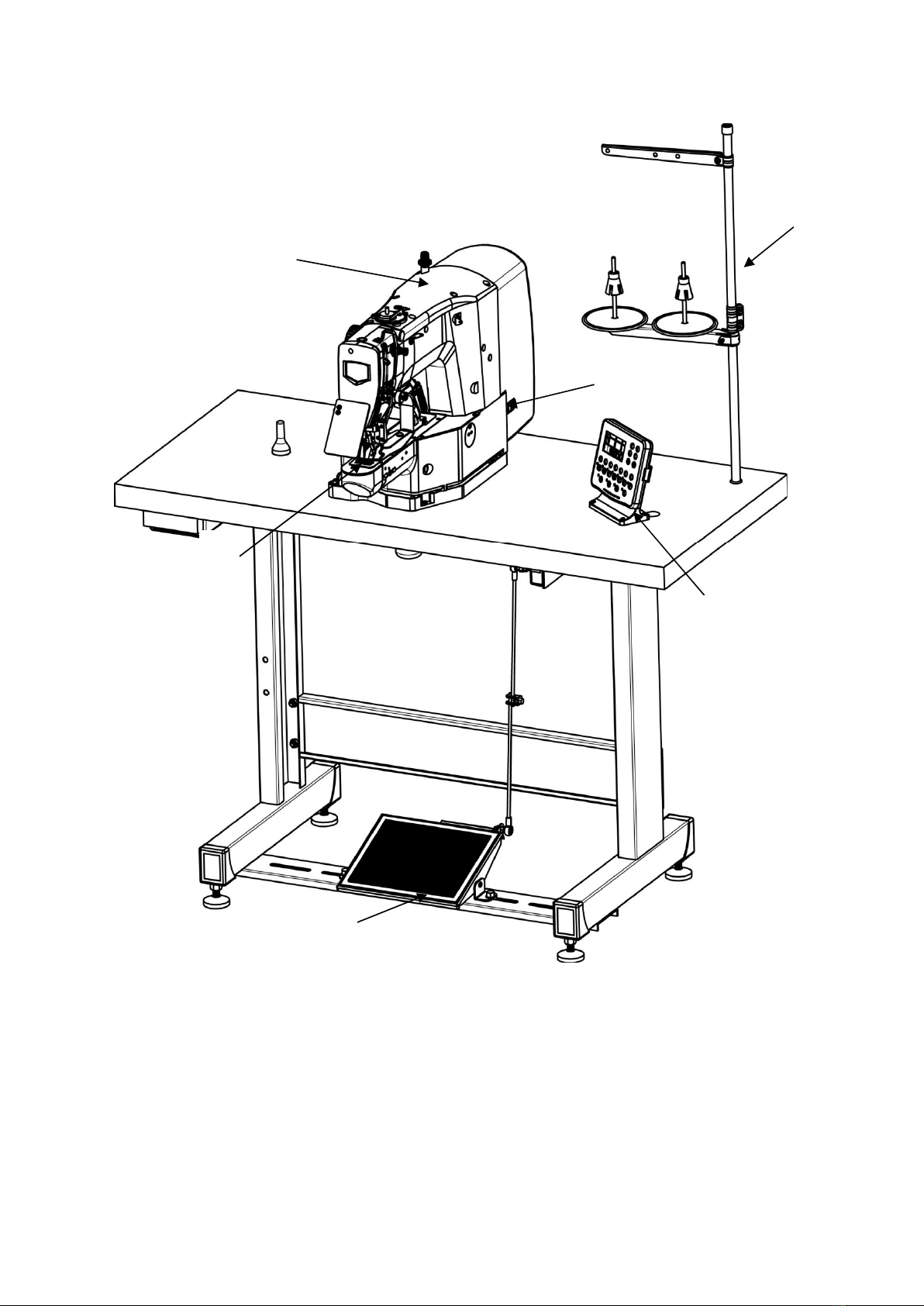
I. INSCAPE...................................................................................................... 1
II. INSTALLATION........................................................................................... 2
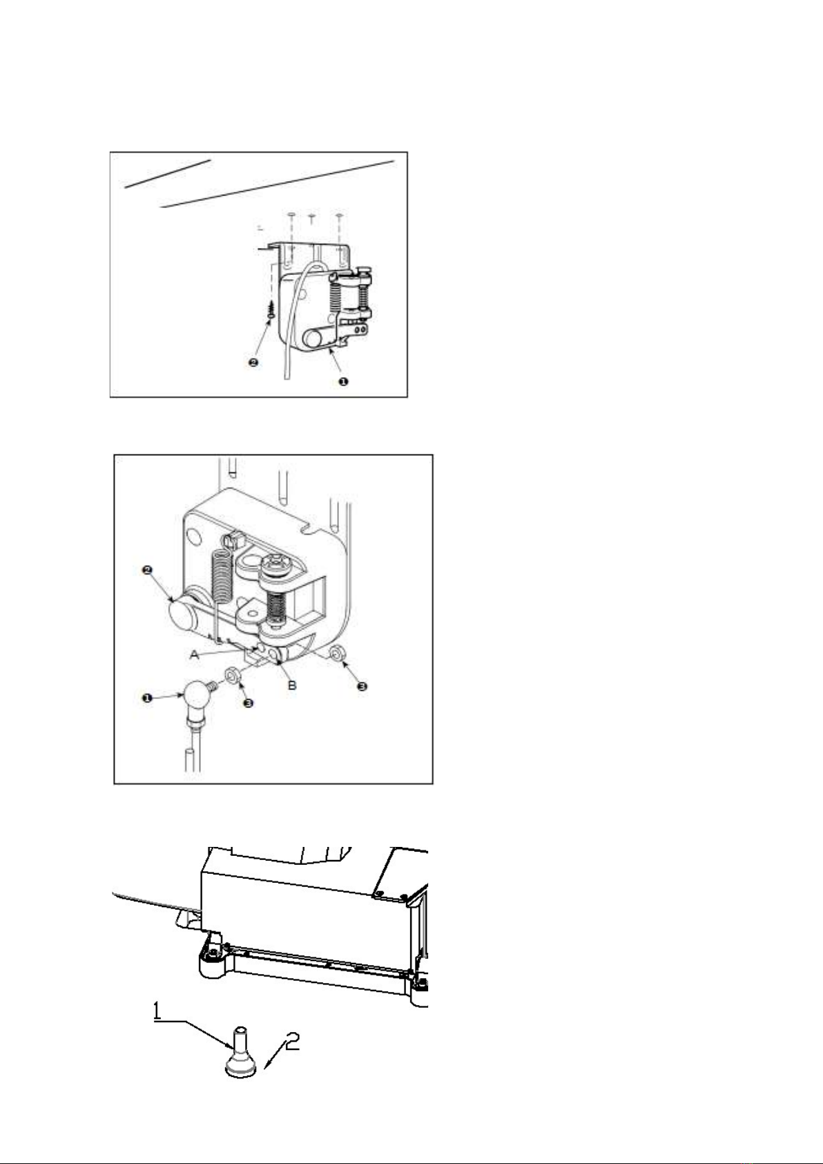
1. Installing the pedal sensor........................................................................................ 2
2. Attaching the connecting rod ................................................................................... 2
3. Installing the head support rod ................................................................................ 2
4. How to carry the sewing machine ............................................................................ 3
5. Installation of the sewing machine head ................................................................. 3
6. Installing the drain receiver and the head support rubber .................................... 4
7. Tilting the sewing machine head.............................................................................. 4
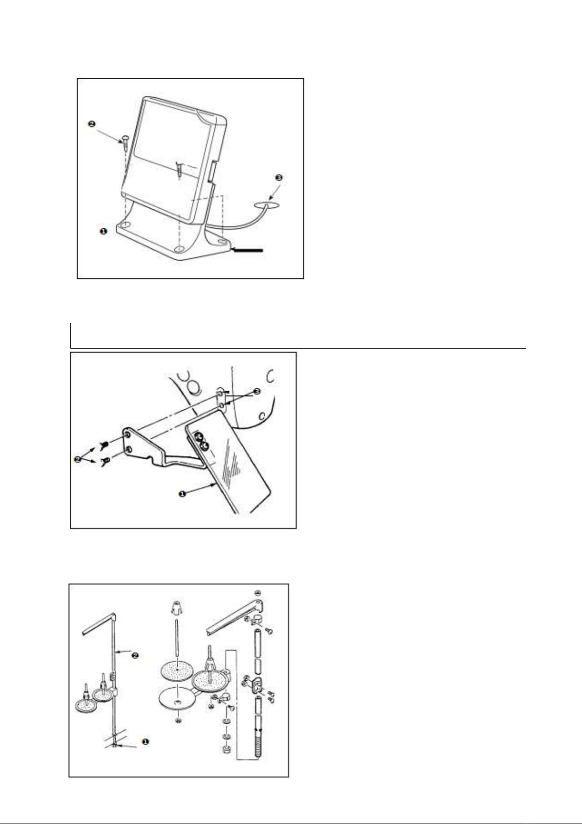
8. Installing the operation panel ................................................................................... 5
9. Installing the eye protection cove ............................................................................ 5
10. Installing the thread stand ...................................................................................... 5
III. OPERATION OF THE SEWING MACHINE............................................... 6
1. Lubrication.................................................................................................................. 6
2. Attaching the needle .................................................................................................. 6
3. Threading the machine head .................................................................................... 7
4. Installing and removing the bobbin case ................................................................ 7
5. Installing the bobbin .................................................................................................. 8
6. Adjusting the thread tension..................................................................................... 8
7. Adjusting the thread take-up spring......................................................................... 8
8. Example of the thread tension.................................................................................. 9
IV. MAINTENANCE......................................................................................... 9
1. Adjusting the height of the needle bar..................................................................... 9
2. Adjusting the needle-to-shuttle relation ................................................................ 10
3. Adjusting the lift of the work clamp foot................................................................ 11
4. The moving knife and counter knife....................................................................... 11
5. Draining waste oil .................................................................................................... 12
6. Amount of oil supplied to the hook ........................................................................ 12

i
Safety Matters for Attention
1. Signs & Definitions of Safety Marks
This User’s Manual and the Safety Marks printed on the products are to enable you to use
this product correctly so as to be away from personal injury. The signs and definitions of
Marks are shown in below:
Danger
The incorrect operation due to negligence will cause the serious personal
injury or even death.
Caution
The incorrect operation due to negligence will cause the personal injury and
the damage of mechanism.
This kind of marks is “Matters for Attention”, and the figure inside the
triangle is the content for attention. (Exp. The left figure is “Watch Your
Hand!”)
This kind of mark is “Forbidden”.
This kind of mark means “Must”. The figure in the circle is the contents that
have to be done. (Exp. The left figure is “Ground!”)
2. Safety Matters for Attention
Danger
For opening the control box, please turn off the power and take away the
plug from socket firstly, and then wait for at least 5 minutes before opening
the control box. Touching the part with high voltage will cause the person
injury.
Caution
Usage Environment
Try not to use this sewing machine near the sources of strong disturbance
like high-frequency welding machine.
The source of strong disturbance will affect the normal operation of the
sewing machine.
The voltage fluctuation shall be within 10% of the rated voltage.
The large fluctuation of voltage will affect the normal operations of sewing
machine, Therefore a voltage regulator is needed in that situation.
Working temperature:0℃~45℃.
The operation of the sewing machine will be affected by environment with
temperature beyond the above range.
Relative Humidity: 35%~85%(No dew inside the machine), or the
operation of sewing machine will be affected.
Safety Matters for Attention
1. Signs & Denitions of Safety Marks
2. Safety Matters for ttention

ii
The supply of compressed gas shall be over the consumption required by
the sewing machine. The insufficient supply of compressed gas will lead to
the abnormal action of sewing machine.
In case of thunder, lightning or storm, please turn off the power and pull
plug out the socket. Because these will have influence on the operation of
sewing machine.
Installation
Please ask the trained technicians to install the sewing machine.
Don’t connect machine to power supply until the installation is finished.
Otherwise the action of sewing machine may cause personal injury once
the start switch is pressed at that situation by mistake.
When you tilt or erect the head of sewing machine, please use both of your
hand in that operation. And never press the sewing machine with strength.
If the sewing machine loses its balance, it will fall into floor thus causes the
personal injury or mechanical damage.
Grounding is a must.
If the grounding cable is not fixed, it may cause the electric-shock and
mis-operation of machine
The entire cables shall be fixed with a distance at 25mm away from the
moving component at least. By the way, don’t excessively bend or tightly
fixed the cable with nails or clamps, or it may cause the fire or electric
shock.
Please add security cover on the machine head.
Sewing
This sewing machine can only be used by the trained staff.
This sewing machine has no other usages but the sewing.
When operating the sewing machine, please remember to put on the
glasses. Otherwise, the broken needle will cause the personal injury in case
the needle is broken.
At following circumstances, please cut off the power at once so as to avoid
the personal injury caused by the mis-operation of start switch:
1.Threading on needles; 2. Replacement of needles; 3. The sewing
machine is left unused or beyond supervision
At working, don’t touch or lean anything on the moving components,
because both of the above behaviors will cause the personal injury or the
damage of the sewing machine.
During working, if the mis-operation happens or the abnormal noise or
smell is found at the sewing machine, user shall cut off the power at once,

iii
and then contact the trained technicians or the supplier of that machine for
solution.
For any trouble, please contact the trained technicians or the supplier of
that machine.
Maintenance & Inspection
Only can the trained technicians perform the repair, maintenance and
inspection of this sewing machine.
For the repair, maintenance and inspection of the electrical component,
please contact the professionals at the manufacturer of control system in
time.
At following circumstances, please cut off the power and pull off the plug at
once so as to avoid the personal injury caused by the mis-operation of start
switch:.
1.Repair, adjustment and inspection;
2.Replacement of the component like curve needle, knife and so on
Before the inspection, adjustment or repair of any gas-driven devices, user
shall cut off the gas supply till the pressure indicator falls to 0.
When adjusting the devices needing the power supply and gas supply,
users can’ t be too careful to follow the entire Safety Matters for Attention.
If the sewing machine damages due to the unauthorized modification, our
company will not be responsible for it.

– 1 –
❶
Machine head
❷
Work clamp fee
❸
Thread stand
❹
Operation panel
❺
Power switch
❻
Pedal
❶
❷
❸
❹
❺
❻
I.INSCAPE
I. INSCAPE

– 2 –
1.Installing the pedal sensor
Install the pedal sensor ❶to the table
with mounting screws ❷supplied with
the unit.
2.Attaching the connecting rod
1)Fix connecting rod
❶
to
installing hole B of pedal lever
❷
with nut
❸
.
2)The pedal depressing stroke is
decreased by fitting connecting
rod
❶
in mounting hole A.
3.Installing the head support rod
Drive head support rod ❶in hole
❷in the machine table.
II.INSTALLATION
II. INSTALLATION
1. Installing the pedal sensor
2. Attaching the connecting rod
3. Installing the head support rod

– 3 –
Please carry the sewing machine as shown in the figure.
5.Installation of the sewing machine head
1)Fit hinge rubber cushion ❶
over the hinge shaft。
2)Install the main body of the
sewing machine on the table with
four bolts❷,four plain washers❸
,
four hexagonal nuts ❹and four
hexagonal nuts ❺
4.How to carry the
sewing machine
1.Carefully prevent slippage of your hand that holds the cover.
2.The sewing machine weighs over 42 kg. Be sure to carry the sewing machine
with two or more people without exceptions.
4. How to carry the sewing machine
5. Installation of the sewing machine head

– 4 –
6.Installing the drain receiver and the head support rubber
1)Fix drain receiver ❷in the installing
hole of table
❶with two setscrews ❸.
2)Screw poly-oiler ❹in waste oil
reservoir ❷.
3)Insert sewing-machine waste oil pipe
❺into poly-oiler ❹.
4)Insert head support rubber ❻into
table ❶.
5)Pass bundle ❼of cords through
slotted hole ❽in
the table
CAUTION !
1.Insert drain pipe ❺until it will go no
further so that it does not come off
poly-oiler ❹when tilting the machine
head.
2.Remove the tape fixing drain pipe ❺
3.When the machine moves out of the
oil pan, please put the screws❽back。
7.Tilting the sewing machine head
Tilt/raise the sewing machine head with both hands taking care not to allow your
fingers to be caught in the head. Turn OFF the power before starting the work so as to
prevent accidents caused by abrupt start of the sewing machine.
❽
When tilting the sewing machine head, tilt
the head gently until it comes in contact with
head support rod❶
CAUTION !
1.Before tilting the sewing machine head,
make sure that head support rod ❶is
attached to the machine table.
2.When raising the sewing machine head, do
not raise it while holding motor cover
❷. It will be the cause of breakage of
motor cover ❷.
3.Be sure to tilt the sewing machine head on
a flat place to prevent it from falling.
6. Installing the drain receiver and the head support rubber
7. Tilting the sewing machine head

– 5 –
8.Installing the
operation panel
Fix operation panel mounting plate ❶
on the table with four wood screws ❷.
Then, pass the cable through hole ❸in
the table.
9.Installing the eye protection cove
Be sure to attach this cover to protect the eyes from the disperse of needle breakage.
Be sure to use eye protection cover ❶
after installing it on installing section ❸
with screws ❷
10.Installing the thread stand
1)Assemble the thread stand unit, and
insert it in the hole in the machine
table.
2)Tighten locknut ❶to fix the
thread stand.
For ceiling wiring, pass the power
cord through spool rest rod ❷
8. Installing the operation panel
10. Installing the thread stand
9. Installing the eye protection cove

– 6 –
Caution!
1.Do not lubricate to the places other than the oil tank and the hook of caution 2 below.
Trouble of components will be caused.
2.When using the sewing machine for the first time or after an extended period of disuse, use
the machine after lubricat
-
ing a small amount of oil to the hook portion.
Check that the place between lower line B
and up-per line A is filled with oil. Fill there
with oil using the oiler supplied with the
machine as accessories when oil is short。
* The oil tank which is filled with oil is
only for lubricating to the hook portion. It is
possible to reduce the oil amount when the
number of rotation used is low and the oil
amount in the hook portion is excessive.
Remove 5 screws ❷on top cover ❶as
shown in the figure, and open top cover ❶.
Then remove the screw ❸, note that there is
an oil seal ❹under the screw ❸, then add
gear oil into the hole, please use up the 150ml
gear oil in the oil pot. Then, install oil seal ❹
on screw ❸and tighten it. Reinstall the top
cover ❶and tighten the screws ❷.
CAUTION:
Please add L-CKC100 gear oil
before using the new machine.
2.Attaching the needle
Loosen setscrew ❶and hold needle ❷
with the long groove ❸facing toward
you. Then fully insert it into the hole in
the needle bar, and tighten setscrew ❶.
Caution!
If the stitches are made as shown in A,
attach the needle facing to the direction B
to a small extent.
III.OPERATION OF THE SEWING MACHINE
WARNING :Turn OFF the power before starting the work so as to prevent accidents caused by
abrupt start of the
1.Lubrication
WARNING :Turn OFF the power before starting the work so as to prevent accidents caused by
abrupt start of the
III. OPERATION OF THE SEWING MACHINE
1. Lubrication
2. Attaching the needle

– 7 –
Pull out the thread by approximately 40mm from the needle after threading through the needle.
3.
TThhrreeaaddiinnggtthheemmaacchhiinneehheeaadd
Caution!
1.When the silicon oil is used, thread through thread guide for silicon ❶(Optional).
2.For thick thread, pass the thread through one hole only of needle bar thread guide ❷
4.Installing and removing the bobbin case
1)Open hook cover ❶.
2)Raise latch ❸of bobbin case ❷, and remove
the bobbin case.
3)When installing the bobbin case, fully insert it
into the shuttle shaft, and close the latch!
Caution!
If it is not fully inserted, bobbin case ❷may slip
off during sewing.
WARNING :Turn OFF the power before starting the work so as to prevent accidents caused by
abrupt start of the
WARNING :Turn OFF the power before starting the work so as to prevent accidents caused by
abrupt start of the
3. Threading the machine head
4. Installing and removing the bobbin case

– 8 –
Caution!
If the bobbin is installed in the bobbin case orienting the reverse direction, the bobbin thread
pulling out will result in an inconsistent state.
7.Adjusting the thread take
-
up spring
5.Installing the bobbin
1)Set the bobbin ❶into bobbin case ❷in the
di- rection shown in the figure.
2)Pass the thread through thread slit ❸of
bobbin case ❷, and pull the thread as it is. By
so doing, the thread will pass under the tension
spring and be pulled out from thread hole ❹.
3)Pass the thread through thread hole ❺of the
horn section, and pull out the thread by 25mm
from the thread hole.
WARNING :Turn OFF the power before starting the work so as to prevent accidents caused by
abrupt start of the
6.Adjusting the thread tension
If thread tension controller No. 1 ❶
is turned clock-wise, the length of
remaining thread on the needle after
thread trimming will be shorter. If it is
turned counterclockwise, the length
will be longer.
Shorten the length to an extent that
the thread is not slipped off.
Adjust needle thread tension from the
operation panel and bobbin thread
tension with
❷
The standard stroke of thread take-up
spring ❶is 8 to 10 mm, and the pressure
at the start is 0.1 to 0.3N.
1)Adjusting the stroke
Loosen setscrew ❷, and turn thread
tension asm. ❸.Turning it clockwise
will increase the moving amount and the
thread drawing amount will in- crease.
5. Installing the bobbin
6. Adjusting the thread tension
7. Adjusting the thread take-up spring

– 9 –
2)Adjusting the pressure
To change the pressure of the thread take-up spring, insert a thin screwdriver into the slot of
thread tension post ❹while screw ❷is tightened, and turn it. Turning it clockwise will
increase the pressure of the thread take-up spring. Turning it counterclockwise will decrease the
pressure.
When using the sewing machine for the first time, adjust the thread tension referring to the table
below
Thread Material Needle thread tension
setting
Thread take-up spring moving
amount [Thread drawing amount]
Strength
Polyester filament thread #50 Wool 30 to 35 10mm [13mm] 0.1N
Polyester spun thread #50 Wool 50 to 55 10mm [13mm] 0.2N
Polyester spun thread #60
(Thread clamp OFF)
T/C broad 30 to 35 8 to 10mm [11 to 13mm] 0.1N
Cotton thread #50 Denim 35 to 45 10mm [13mm] 0.1N
Cotton thread #20 Denim 35 to 45 8 to 10mm [11 to 13mm] 0.1N
8.Example of the thread tension
1.Adjusting the height of the
needle bar
IV.MAINTENANCE
Bring needle bar ❶to the lowest position of its stroke. Loosen needle bar connection screw ❷and adjust
so that upper marker line ❹engraved on the needle bar aligns with the bottom end of needle bar bushing,
lower❸.
Caution!
After the adjustment, make sure that there is no uneven torque.
*When stitch skipping occurs in accordance with the sewing conditions, adjust the height of the needle bar so
as to lower it by 0.5 to 1 mm from the needle bar engraved line ❹
WARNING : Turn OFF the power before starting the work so as to prevent accidents caused by
abrupt start of the
8. Example of the thread tension
1. Adjusting the height of the needle bar
IV. MAINTENANCE

– 10 –
4)Loosen setscrew ❼of the shuttle,
and adjust the longitudinal position
of the shuttle. To do this adjustment,
turn shuttle race adjusting shaft ❽
clockwise or counterclockwise to
provide a 0.05to 0.1 mm clearance
between needle ❺and the blade
point of inner hook ❹.
5)After adjusting the longitudinal
position of the shuttle, further adjust
to provide a 7.5 mm clearance
between the needle and the shuttle
by adjusting the rotating direction.
Then tighten set-screw ❼of the
shuttle.
1)Turn the handwheel by hand. When
needle bar❶has gone up, adjust so
that lower marker line❷engraved on
the needle bar aligns with the bottom
end of the needle bar bushing ❸,
lower
2.Adjusting the needle
-
to
-
shuttle relation
Loosen setscrew $ in the driver. Open
inner hook pressers $ to the right and
left, and re- move inner hook presser $
Caution!
At this time, be careful not to let inner
hook ❹come off and fall.
3)Adjust so that the blade point of
inner hook ❹aligns with the center
of needle ❺, and that a clearance of 0
mm is provided between the front end
of the driver and the needle as the
front end face of driver❻receives the
needle to prevent the needle from being
bent. Then tighten setscrew $ of the
driver.
WARNING :Turn OFF the power before starting the work so as to prevent accidents caused by
abrupt start of the
2. Adjusting the needle-to-shuttle relation

– 11 –
Caution!
If the sewing machine is left unused for a long time, or after clearing the area sur- rounding the
hook section, apply a little quantity of oil to race section ❾and felt ®before using the sewing
machine.
Caution!
At this time, be careful not to cause work clamp foot lever support plate ❼to interfere with feed
bracket ❽.
If the work clamp foot lever support plate interferes with the wiper, readjust the height of the
wiper using setscrew ❾in the wiper installing base
4.
T
he moving knife
and counter knife
1)Loosen adjusting screw ❸so that a
clearance of18.5 mm is provided between the
front end of the throat plate and the top end of
thread trimmer lever, small ❶. To adjust,
move the moving knife in the direction of
arrow.
2)Loosen setscrew ❺so that a clearance of
0.5 mm is provided between needle hole guide
❷and counter knife ❹. To adjust, move the
counter knife.
3.Adjusting the lift of the work clamp foot
1)With the machine in stop mode, remove
six set-screws ❶of the top cover, and take
off top cover❷.
2)Apply L-shaped wrench ❸to socket bolt
❺of clamp ❹, and loosen the socket bolt.
3)Push down L-shaped wrench ❸to
increase the lift of the work clamp foot, or
pull it up to de- crease the lift.
4)After the adjustment, securely tighten
socket bolt❺.
5)If the right and left work clamp feet are
not levelled, loosen fixing screw ❻and
adjust the position of the work clamp foot
lever support plate ❼to level them
WARNING :Turn OFF the power before starting the work so as to prevent accidents caused by
abrupt start of the
4. The moving knife and counter knife
3. Adjusting the lift of the work clamp foot

– 12 –
Caution!
1.The state of standard delivery is the position where ❸is lightly screwed in and returned by 4
turns.
2.When reducing the amount of oil, do not screw in the screw at once. Ob- serve the state for
approximately half a day at the position where ❸is screwed in and returned by 2 turns. If
reducing is excessive, worn-out of the hook will result.
5.Draining waste oil
When polyethylene oiler ❶becomes
filled with oil, remove polyethylene oiler
❶and drain the oil.
1)Loosen setscrew ❶and remove setscrew
❶.
2)When screwing in adjustment screw ❷,
the amount of oil of oil pipe, left ❹can be
reduced.
3)After the adjustment, screw in setscrew ❶
and fix it.
6.Amount of oil supplied to the hook
5. Draining waste oil
6. Amount of oil supplied to the hook
Other manuals for K-1E
1
Table of contents
Other JUKI Sewing Machine manuals

JUKI
JUKI DSC-246 User manual

JUKI
JUKI LZ-2290A-SS-7 Quick start guide

JUKI
JUKI MH-481 User manual

JUKI
JUKI PS-800-12080 User manual

JUKI
JUKI LBH-1796A User manual

JUKI
JUKI HZL-DX series User manual

JUKI
JUKI SC-510 Quick start guide

JUKI
JUKI AB-1351 User manual

JUKI
JUKI LZ-2280N Series Quick start guide

JUKI
JUKI LU-1510N-7 User manual

JUKI
JUKI SC-910N Quick start guide

JUKI
JUKI HZL-UX8 User manual

JUKI
JUKI DMN-5420N-7 User manual

JUKI
JUKI DDL-552-2 User manual

JUKI
JUKI AK85C User manual

JUKI
JUKI MO-6900R Series User manual

JUKI
JUKI MO-735 User manual

JUKI
JUKI LH-3500A series User manual

JUKI
JUKI LU-1510 User manual

JUKI
JUKI MC37 User manual