JUKI MF-7500 Series User manual

I
INSTRUCTION MANUAL
MF-7500(D)/UT37

i
CONTENTS
I. SPECIFICATIONS.............................................................................................................1
II. AT THE BEGINNING........................................................................................................1
III. INSTALLING THE ACCESSORIES................................................................................2
1. Installing the presser lifting cylinder ..................................................................................... 2
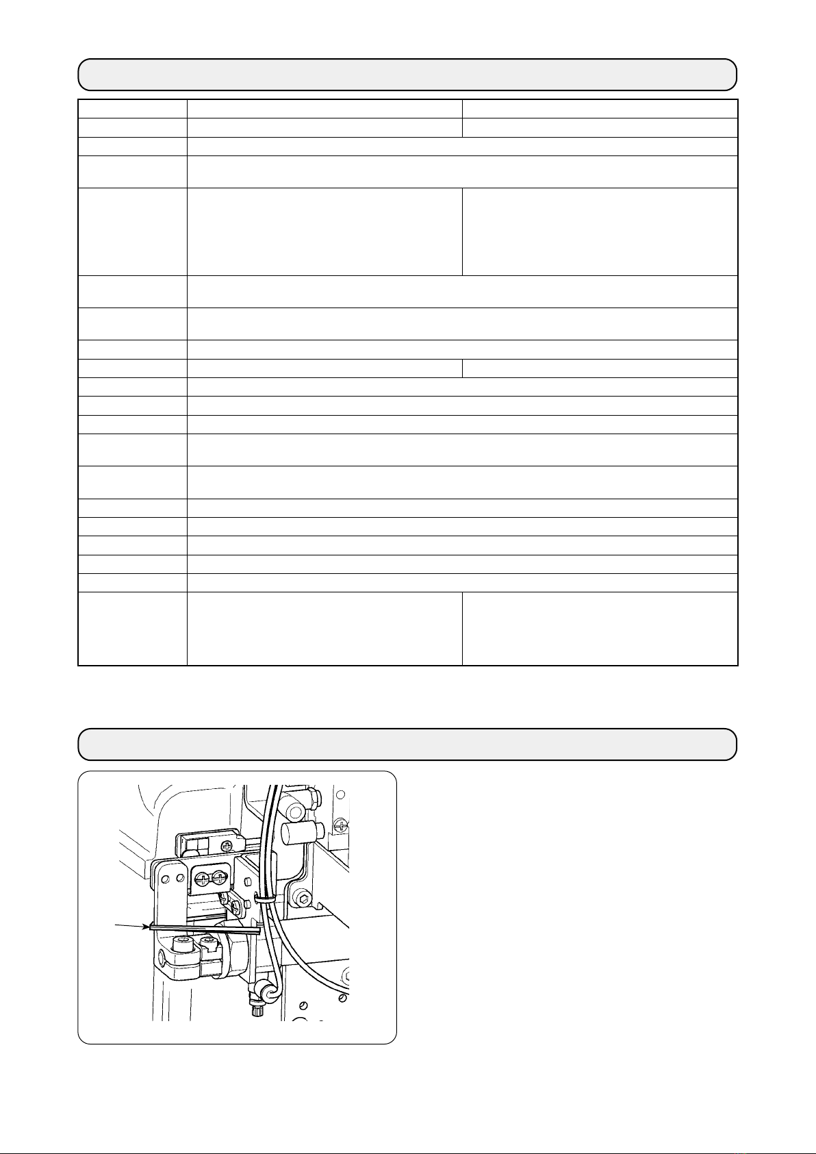
2. Installing the air regulator....................................................................................................... 2
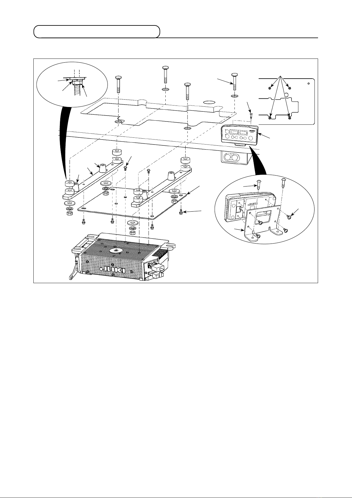
3. Installation and setting SC-921............................................................................................... 3
(1) Installing the SC-921 on the table ( Semi-submerged type ).............................................. 3
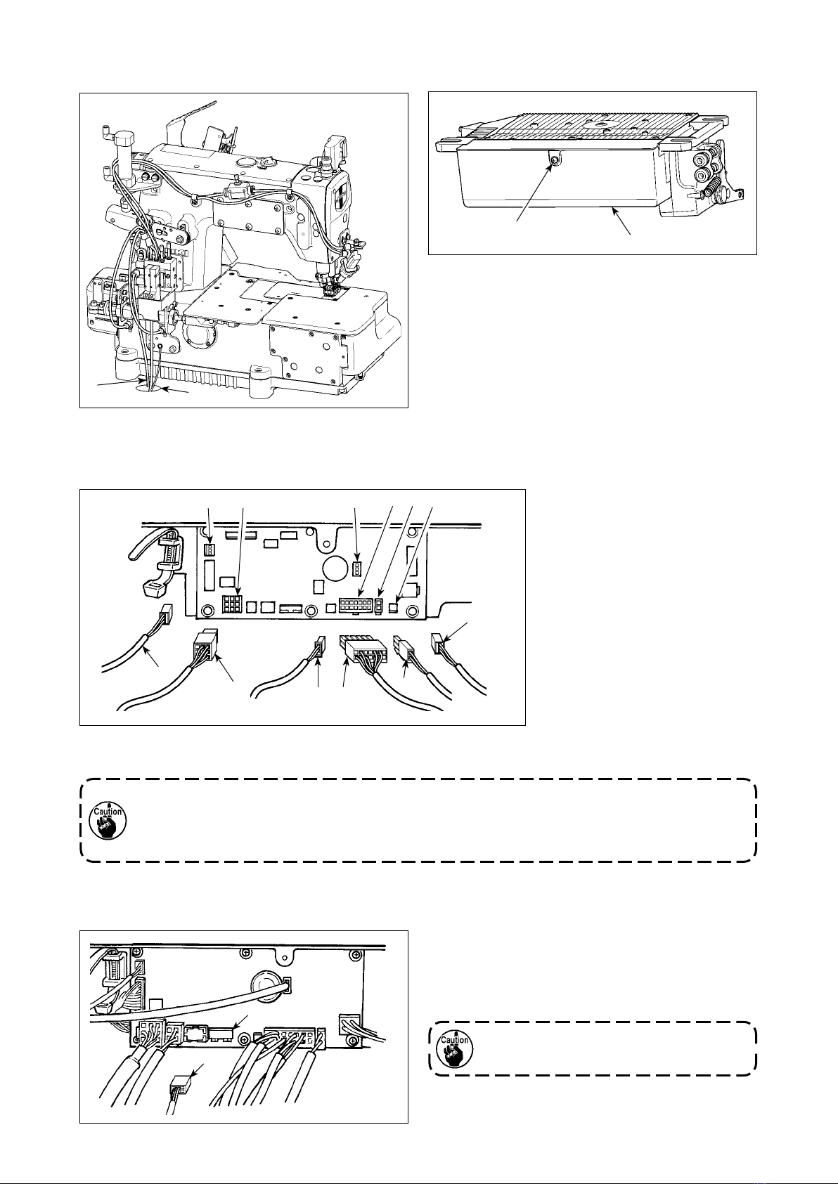
(2) Connecting the cords ............................................................................................................ 4
(3) Setting procedure of the machine head............................................................................... 5
(4) Setting the lower stop position of the needle bar ............................................................... 6
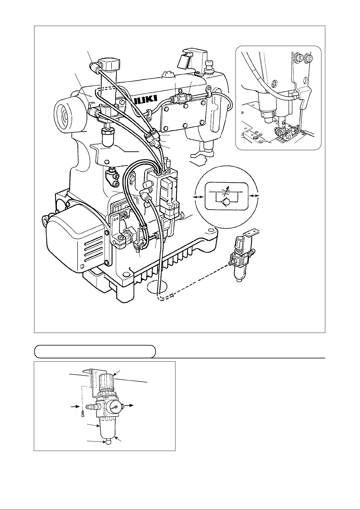
IV. AIR PIPING DRAWING...................................................................................................7
1. Piping of the thread trimmer device....................................................................................... 7
2. Adjusting the air regulator ...................................................................................................... 8
V. THREADING THE MACHINE HEAD...............................................................................9
VI. ADJUSTING THE LOOPER THREAD TRIMMER MECHANISM ................................10
1. Adjusting the thread trimmer air cylinder ........................................................................... 10
2. Adjusting the Lower knife ..................................................................................................... 11
3. Adjusting the position of clamp pressure adjusting spring .............................................. 11
4. Adjusting the knife engagement and the knife pressure adjusting spring ...................... 11
5. Adjusting the pressure of clamp spring .............................................................................. 11
6. Initial position of the looper thread trimmer mechanism................................................... 12
7. Adjusting the stopper............................................................................................................ 12
8. Adjusting the height of the lower knife................................................................................ 12
9. Adjusting the longitudinal position of the blade point of lower knife .............................. 13
10. Adjusting the thread trimmer sensor................................................................................... 13
11. Adjusting the speed of looper thread trimmer.................................................................... 13
VII. ADJUSTING THE THREAD RELEASE MECHANISM ...............................................14
1. Adjusting the disk-rise .......................................................................................................... 14
2. Adjusting the thread release hook ....................................................................................... 14
VIII.
ADJUSTING THE TOP COVERING THREAD TRIMMER MECHANISM ............................. 15
1. Adjusting the engagement of knives ................................................................................... 15
2. Adjusting the pressure of clamp spring .............................................................................. 15
3. Adjusting the position of the blade point of moving knife ................................................ 15
4. Adjusting the speed of moving knife ................................................................................... 16
IX. ADJUSTING THE AIR-BLOW WIPER (ACCESSORIES)............................................17
1. Installing the air-blow wiper.................................................................................................. 17
2. Adjusting the air-blow wiper................................................................................................. 17
X. MAINTENANCE.............................................................................................................18
1. Cleaning the motor fan.......................................................................................................... 18

– 1 –
❶
I. SPECIFICATIONS
Model name High-speed, at-bed coverstitch machine
Semi-dry head, high-speed, at-bed coverstitch machine
Model MF-7500 series MF-7500D series
Stitch type ISO standard 406, 407, 602, and 605
Example of applica-
tion
Hemming and covering for knits and general knitted fabrics
Sewing speed Max. 6,500 sti/min (at the time of intermittent operation)
V-belt type
Max. 6,000 sti/min (at the time of intermittent operation)
Direct-drive type
Speed of stitch at the delivery:
4,500 sti/min (at the time of intermittent operation)
Max. 5,000 sti/min (at the time of intermittent operation)
V-belt type
Max. 5,000 sti/min (at the time of intermittent operation)
Direct-drive type
Speed of stitch at the delivery:
4,000 sti/min (at the time of intermittent operation)
Needle gauge 3-needle ..... 4.8 mm, 5.6 mm, and 6.4 mm
2-needle ..... 3.2 mm and 4.0 mm
Dierential feed ratio 1 : 0.7 to 1 : 2 (stitch length : less than 2.5 mm)
Micro-dierential feed adjustment mechanism is provided. (Micro-adjustment)
Stitch length
1.2 mm to 3.6 mm (can be adjusted up to 4.4 mm)
Needle UY128GAS #9S to #14S (standard #10S) UY128GAS #9S to #12S (standard #10S)
Needle bar stroke 31 mm (33 mm when the eccentric pin is changed over)
Dimensions (Height) 451 x (Width) 523 x (Length) 279
Weight 49 kg (With pneumatic type thread trimmer) , 46 kg
Lift of presser foot 8 mm (needle gauge : 5.6 mm without top covering), and 5 mm (with top covering)
Micro-lifter mechanism is provided.
Feed adjustment
method
Main feed............... dial type stitch pitch adjustment method
Dierential feed ..... lever adjustment method (micro-adjustment mechanism is provided.)
Looper mechanism Spherical rod drive method
Lubricating system Forced lubrication method by gear pump
Lubricating oil JUKI GENUINE OIL 18
Oil reservoir capacity Oil gauge lower line : 600 cc to upper line : 900 cc
Installation Semi-submerged type
Noise - Equivalent continuous emission sound pressure lev-
el (LpA) at the workstation :
A-weighted value of 76.5 dB; (Includes KpA = 2.5
dB); according to ISO 10821- C.6.2 -ISO 11204
GR2 at 4,500 sti/min.
- Equivalent continuous emission sound pressure lev-
el (LpA) at the workstation :
A-weighted value of 74.0 dB; (Includes KpA = 2.5
dB); according to ISO 10821- C.6.2 -ISO 11204
GR2 at 4,000 sti/min.
Remove xed band ❶ for transportation before setting
up the sewing machine.
II. AT THE BEGINNING

– 2 –
❶
❷
❸
❹,❼
❺
❻
1 to 2 mm
❽
❾
1. Installing the presser lifting cylinder
III. INSTALLING THE ACCESSORIES
WARNING :
To protect against possible personal injury due to abrupt start of the machine, be sure to start the
following work after turning the power o and ascertaining that the motor is at rest.
1) Install presser lifting cylinder asm. ❶ to the sewing
machine with screws ❸, washers ❹ and spring
washers ❼.
2) Tighten screw ❸ in such manner that a clearance
of 1 to 2 mm is provided between cap ❾ at the top
end of presser lifting cylinder asm. ❶ and presser
lifting lever ❷.
If the clearance cannot be adjusted to 1 to 2 mm,
adjust the height of nut ❽ and cap ❾ to obtain the
correct clearance between the cap and lever.
3) Adjust the height of screw ❺ referring to the In-
struction Manual for MF-7500 (VI-15. Adjusting
the presser foot lift ), and tighten nut ❻.
4) Stroke of cylinder asm. ❶ is 30 mm. Make sure
that presser lifting lever ❷ comes in contact with
screw ❺ within the range of cylinder stroke.
2. Installing the air regulator
❶
❷
❺
❹
B
A
❸
1) Install pressure gauge ❺ to regulator main body ❶.
2) Attach joint ❸ to air intake port A, and joint ❹ to
exhaust port B.
3) Install air regulator main body ❶ under the table
with wood screw ❷.

– 3 –
❽
❾
❼
❻
❶
❷
❹
❷
❸
❺
❻
(1) Installing the SC-921 on the table ( Semi-submerged type )
3. Installation and setting SC-921
Convex
washer
Spring
washer
Hexagonal nuts
Fig. A
1) Install right and left support plates ❶ and two rubber seats ❷ of the respective support plates.
2) Install control box mounting plate ❸ on the control box with four screws ❹.
3) Install the parts assembled in Step 2) on the underside of support plates ❶ with four screws ❺.
4) Install support plates ❻ and the control box on the table with mounting bolts asm. ❶ supplied with the unit. At
this time, insert the nuts and washers supplied with the unit as illustrated in Fig. A so that the support plates
and the control box are securely xed.
5) Install the control box (or the one equipped with a small sized motor unit) on the table. Then, install the sewing
machine head on the table. (Refer to the Instruction Manual for the sewing machine.)
6) Install the mounting plate ❾ on the CP-18 panel ❼ with four tapping screws ❽ supplied with the unit.
At this time, take care not to allow the cable to be caught under the mounting bracket.
7) Install CP-18 panel ❼ on the table with wood screw .

– 4 –
❶A
❼
❹
❺
❽
❸
❻
❾
❷
B
(2) Connecting the cords
1) Pass cords ❶ of the thread trimming solenoid,
reverse-stitching solenoid, etc. and the cord from
the motor through hole A in the table to route them
down under the machine table.
2) Loosen screw B in cover ❷ with a screwdriver to
open the cover.
3) Connect 14P code ❸ coming
from the machine head to con-
nector ❻ (CN36).
4) Insert 3P cord ❾ coming from
the machine head into connec-
tor (CN42).
5) Insert presser foot lifter cord 2P
❹ into connector ❼ (CN37).
6) Connect connector ❺ coming
from the motor to connector ❽
(CN30) on the circuit board.
7) Insert pedal sensor cable into connector (CN34).
8) Insert motor fan cord into connector .
Be sure to securely insert the respective connectors after checking the inserting directions since all con-
nectors have the inserting directions. (When using a type with lock, insert the connectors until they go to
the lock.) The sewing machine is not actuated unless the connectors are inserted properly. In addition, not
only the problem of error warning or the like occurs, but also the sewing machine and the control box are
damaged.
[Connecting the connector for the operation panel]
Be sure to turn OFF the power before con-
necting the connector.
The connector for the operation panel is provided.
Paying attention to the orientation of the connector ,
connect it to connector (CN38) located on the circuit
board. After the insertion, securely lock the connectors
to prevent them from coming o easily.

– 5 –
❹❸❷❶
❹❸❷❶
❹❸❷❶ Type of machine head Model name
F75 MF-7500/UT35
MF-7500/UT37
F75d MF-7500D/UT35
MF-7500D/UT37
(3) Setting procedure of the machine head
For the operation panel other than CP-18, refer to the Instruction Manual for the operation panel to be used
for the setting procedure of the machine head.
1) Call function setting No. 95.
2) The type of machine head can be se-
lected by pressing
switch
❸
(
switch
❹
).
* Refer to the "MACHINE HEAD LIST"
on the separate sheet or the Instruc-
tion Manual for the machine head of
your sewing machine for the type of
the machine head.
3) After selecting the type of machine
head, by pressing switch ❶ (
switch ❷), the step proceeds to 96
or 94, and the display automatically
changes to the contents of the setting
corresponding with the type of ma-
chine head.

– 6 –
❹❸❷❶
(4) Setting the lower stop position of the needle bar
Call function setting No. 122. Check to
be sure that the lower stop position of the
needle bar is as shown in Fig. 1. If not,
adjust the lower stop position of the nee-
dle bar properly using function setting No.
122. (Adjustment can be made within the
range of ±15°).
Fig. 1

– 7 –
⑪
③
④
⑨
①
②
⑩
⑨
⑩
⑪
⑨
⑪
IV. AIR PIPING DRAWING
WARNING :
To protect against possible personal injury due to abrupt start of the machine, be sure to start the
following work after turning the power o and ascertaining that the motor is at rest. In addition, cut the air
supply from air compressor.
1. Piping of the thread trimmer device
1. Piping drawing with the needle thread trimmer.

– 8 –
A
③
④
⑥
①
③
⑤
③
⑤
②
2. Piping drawing for air blow.
2. Adjusting the air regulator
1) Insert the air hose to air regulator ❶.
2) Use the air pressure at 0.4 to 0.5 MPa (4 to 5 kgf/
cm2).
3) Draw up regulator knob ❷, turn knob ❷and ad-
just the pointer to 0.4 to 0.5 MPa to adjust the air
pressure.
4) After the adjustment, press downward regulator
knob ❷.
5) When drainage is collected at section A of regula-
tor ❶ during using, press drain cock ❸ to dis-
charge the drainage.
Air hose
❶
❷
❸

– 9 –
❶ ❷
❶
❷
* For the adjustment procedure other than the above, refer to the Instruction Manual for MF-7500.
When the thread tension located in the face plate section is used for the machine with automatic
thread trimmer, the length of needle thread remaining on the needle is shortened and slip-o of the
thread at the start of sewing may occur.
Thread the machine head according to the following threading illustrations.
WARNING :
To protect against possible personal injury due to abrupt start of the machine, be sure to start the
following work after turning the power o and ascertaining that the motor is at rest. If threading is wrong,
stitch skipping, thread breakage, needle breakage or irregular stitches will be caused. So, be careful.
V. THREADING THE MACHINE HEAD

– 10 –
❶
❸
18 mm
❷
VI. ADJUSTING THE LOOPER THREAD TRIMMER MECHANISM
WARNING :
To protect against possible personal injury due to abrupt start of the machine, be sure to start the
following work after turning the power o and ascertaining that the motor is at rest. In addition, cut the air
supply from air compressor.
1) Stroke of air cylinder ❸ is 18 mm.
When adjusting the stroke, loosen setscrew ❷of
collar ❶ and move collar ❶ to the right or left to
adjust.
1. Adjusting the thread trimmer
air cylinder

– 11 –
1) The looper thread is held by clamp pressure ad-
justing spring after thread trimming.
2) Holding pressure of the looper thread can be ad-
justed by turning screw ❽.
3) When screw ❽ is turned clockwise, the holding
pressure is increased and turned counterclockwise,
the pressure is decreased.
4) Make the holding pressure as low as possible with-
in the range of holding the looper thread.
1) Loosen screws ❼and ❽, and adjust the position
of upper knife so that the engagement of the
upper knife with the lower knife is 0.5 mm when
lower knife ❹ moves to the extreme right.
2) At the same time, adjust so that a clearance of 0.5
to 1 mm is provided between knife pressure adjust-
ing spring and clamp pressure adjusting spring
.
3) After the adjustment, tighten screws ❼.
1) Set lower knife ❹ and lower knife holder ❺ with
setscrews ❻ at the position of the illustration.
2. Adjusting the Lower knife
3. Adjusting the position of clamp
pressure adjusting spring
1) Loosen screws ❾.
2) Adjust so that a clearance of 2.5 ± 0.5 mm is pro-
vided between the top end of clamp pressure ad-
justing spring and the top end of lower knife ❹
when the lower knife ❹ is brought to the rightmost
position.
3) After the adjustment, tighten screws ❾.
4. Adjusting the knife
engagement and the knife
pressure adjusting spring
5. Adjusting the pressure of
clamp spring
❹
❺
❻
65.5 mm
0.5 mm
❹
❽
❼❾
2.5 ± 0.5 mm
Clearance of 0.5 to 1 mm
❹

– 12 –
22 ± 0.5 mm
❹
0.3 to 1 mm
0 to 0.1 mm
❹
When the needle bar advances from its upper dead
point by 15º, the clearance of 0 to 0.1 mm has to be
provided between the undersurface of lower knife ❹
and the top surface of looper .
8. Adjusting the height of the
lower knife
When the lower knife ❹ is located at its leftmost posi-
tion, the top end of the lower knife ❹ has to be spaced
22 ± 0.5 mm from the center of needle bar.
6. Initial position of the looper
thread trimmer mechanism
Check the leftmost point with the pneumatic device
turned on. Adjustment should be carried out with the air
pressure set at 0.5 MPa.
Adjust the position of stopper so that a clearance of
0.3 to 1 mm is provided between looper and clamp
pressure adjusting spring when the counter knife is
located at its leftmost position (forward end).
7. Adjusting the stopper
Perform the work with the needle bar at the
highest position when actuating the thread
trimmer mechanism by hand.
Center of needle
bar

– 13 –
❺
❹
❸
9. Adjusting the longitudinal
position of the blade point of
lower knife
Perform the work with the needle bar at the
highest position when actuating the thread
trimmer mechanism by hand.
1) Advance the needle bar by 15º from its upper dead
point.
2) Adjust so that the blade point of lower knife ❹is
placed at the center of thickness of the looper
when the lower knife is projected until its top
end is aligned with the end face of the looper .
3) Loosen nut , move lower knife holder ❺ to and
fro, and adjust the position of the blade point of
lower knife ❹.
4) After the adjustment, tighten nut .
The safety switch is installed so that the sewing ma-
chine does not start unless the looper thread trimmer
device returns to its home position.
1) Loosen setscrews .
2) Adjust switch plate so that LED of thread trim-
mer sensor lights up in the state that the thread
trimmer device is fully returned to its home position.
3) Tighten setscrews .
Perform the work with the needle bar at the
highest position when actuating the thread
trimmer mechanism by hand.
10. Adjusting the thread trimmer
sensor
Speed of the looper thread trimmer device can be changed
with speed controllers
and
of air cylinder
❸.
1) When you desire to change the protruding speed
of lower knife, loosen the nut of speed controller ,
and turn the adjustment screw.
When you desire to change the returning speed of
lower knife, loosen the nut of speed controller ,
and turn the adjustment screw.
2) After the adjustment, tighten the nuts of speed con-
trollers and .
11. Adjusting the speed of
looper thread trimmer
• When the protruding speed of lower knife is
slow, thread trimming failure will be caused.
• When the returning speed of lower knife is
fast, lower thread clamp failure or uneven
needle thread remaining length will be
caused.
Blade point of lower knife is in the
center of thickness of looper.

– 14 –
❶
❷
❸
❹
❺
❻
❼
❽
❾
*A
35 ± 1 mm
WARNING :
To protect against possible personal injury due to abrupt start of the machine, be sure to start the
following work after turning the power o and ascertaining that the motor is at rest. In addition, cut the air
supply from air compressor.
VII. ADJUSTING THE THREAD RELEASE MECHANISM
1) Loosen setscrew ❷ in adjustment cam ❶, turn
adjustment cam ❶ and disk-rise plate ❸ moves up
or down.
2) Adjust the clearance between the click section of
disk-rise plate ❸ and thread tension disk ❹ to 0.2
to 0.5 mm, and tighten setscrew ❷.
3) If the click section of disk-rise plate ❸ comes in
contact with thread tension disk ❹, sewing trouble
will be caused. So, be careful.
When the thread remaining length at the start
of sewing is short, stitch skipping or slip-o
of thread from needle eyelet at the start of
sewing is apt to occur.
1. Adjusting the disk-rise
2. Adjusting the thread release
hook
1) Loosen setscrew ❺. Adjust so that the top end of
tension release rod ❻ is spaced 45 ± 1 mm from
the top end of take-up thread guide ❼. Then, tight-
en setscrew ❺.
2) Loosen setscrew ❾, move the position of thread
release hook ❽ up or down, and the thread re-
maining length at the start of sewing can be adjust-
ed.
• When the position of thread release hook ❽is
raised, the thread remaining length at the start
of sewing is decreased and when it is lowered,
the thread remaining length at the start of sew-
ing is increased.
• If stitch skipping occurs at the beginning of
sewing when using non-elastic thread, proper-
ly adjust the remaining length of top-covering
thread at the start of sewing using setscrew
and minimize the remaining length of looper
thread at the start of sewing using screw .
*A
Clearance between click and disk is 0.2 to 0.5 mm.
(5 places)

– 15 –
0.5 mm
❶
❷❸
❹
❺
❻
❼
❽
0.5 mm
Fig. A
❷
❾
❷
❾
VIII.
ADJUSTING THE TOP COVERING THREAD TRIMMER MECHANISM
WARNING :
To protect against possible personal injury due to abrupt start of the machine, be sure to start the
following work after turning the power o and ascertaining that the motor is at rest. In addition, cut the air
supply from air compressor.
Make sure that the moving knife does not in-
terfere with other components such as press-
er, needle, spreader, etc. within the working
range of moving knife ❷.
1. Adjusting the engagement of
knives
1) Adjust so that the engagement of xed knife ❶
with moving knife ❷is 0.5 mm.
2) When adjusting the engagement, loosen setscrews
❹ and move knife holder ❺ up or down to adjust.
2. Adjusting the pressure of
clamp spring
1) Top covering thread is held with clamp spring ❸
after thread trimming.
2) Holding pressure can be adjusted by loosening nut
❻ and turning screw ❼.
3) Holding pressure is increased when tightening
screw ❼ and it is decreased when loosening screw
❼.
4) After the adjustment, tighten nut ❻.
5) Make the holding pressure as low as possible with-
in the range of holding the top covering thread.
3. Adjusting the position of the
blade point of moving knife
1) Bring the needle bar to its highest position.
2) When hinge screw ❽ is lowered, moving knife ❷
lowers together.
3) Adjust so that the hook of moving knife ❷ enters
the recess in the top face of spreader ❾ to be
brought to the position where the moving knife
catches the top covering thread when moving knife
❷ is brought to the lowermost position. Then, tight-
en screws , and .
Adjust the moving knife vertically so that a clear-
ance of 0.5 mm is provided between the recess
section of spreader ❾ and the moving knife, and
laterally so that the moving knife ❷ is brought to
the center of the width of recess in spreader, as
illustrated in Figure A.
4) Screws are for adjusting vertical position of the
knife, screws for adjusting lateral position of
the knife, and screws for adjusting angle of the
knife.

– 16 –
❶
❷
❸
・
When the protruding speed of moving
knife is slow, thread trimming failure will
be caused.
・
When the returning speed of moving knife
is fast, needle thread clamp failure will be
caused.
4. Adjusting the speed of
moving knife
Stroke of air cylinder ❶ is 20 mm.
Speed of the moving knife can be changed with speed
controllers ❷and ❸.
1) When you desire to change the protruding speed
of moving knife, loosen the nut of speed controller
❷ and turn the adjustment screw.
When you desire to change the returning speed of
moving knife, loosen the nut of speed controller ❸
and turn the adjustment screw.
2) After the adjustment, tighten the nuts of speed con-
trollers ❷and ❸.

– 17 –
❶
❷
❸
IX. ADJUSTING THE AIR-BLOW WIPER (ACCESSORIES)
WARNING :
To protect against possible personal injury due to abrupt start of the machine, be sure to start the
following work after turning the power o and ascertaining that the motor is at rest. In addition, cut the air
supply from air compressor.
1. Installing the air-blow wiper
1) When using air-blow wiper ❶, remove the top
covering thread trimmer device.
2) Tighten air-blow wiper ❶ with setscrews ❷.
3) Perform piping referring to “IV. AIR PIPING
DRAWING” p.7.
2. Adjusting the air-blow wiper
Adjust the air-blow position of air-blow wiper ❶.
1) Adjust so that the air outlet of air-blow wiper ❶is
positioned in the rear of needle and slightly on the
lower side of needle eyelet of the left needle when
the needle bar is in the highest position.
2) After the adjustment, temporarily tighten setscrews
❷.
3) Supply air from the air compressor and turn the
power ON.
4) When the back part of the pedal of sewing machine
is depressed, the presser goes up and simultane-
ously air blows from air-blow wiper ❶. Re-adjust
the position of air-blow wiper ❶ so that air blows
only to the needle thread in the rear of the needle
eyelet.
5) After the re-adjustment, tighten setscrews ❷.
• When air blows in front of the needle, nee-
dle thread slips from the needle eyelet. So,
be careful.
• Adjust the air-blow strength with speed
controller ❸.
•
Handwheel may rotate up to the xed position
when turning ON the power. So, be careful.

– 18 –
X. MAINTENANCE
1. Cleaning the motor fan
Open the motor cover ❶ and remove the screws ❷.
Clean up the periphery of the motor fan ❸ and the mo-
tor cover ❶.
After the completion of cleaning, re-install the motor fan
❸ and the motor cover ❶.
❶
❷
❸
WARNING :
To protect against possible personal injury due to abrupt start of the machine, be sure to start the
following work after turning the power o and ascertaining that the motor is at rest. In addition, cut the air
supply from air compressor.
Other manuals for MF-7500 Series
3
This manual suits for next models
1
Table of contents
Other JUKI Sewing Machine manuals

JUKI
JUKI DX-1500QVP User manual

JUKI
JUKI LU-2810 Series User manual

JUKI
JUKI AMS-215D User manual

JUKI
JUKI DP-2100 User manual

JUKI
JUKI DDL-9000A User manual

JUKI
JUKI LK-1930 User manual

JUKI
JUKI LU-2860NV User manual

JUKI
JUKI MF-7000 Series Quick start guide

JUKI
JUKI LK-1850 Series User manual

JUKI
JUKI MO-2404 User manual

JUKI
JUKI LZ-271 User manual

JUKI
JUKI TL-2200QVP Mini User manual

JUKI
JUKI DDL-8700B-7 User manual

JUKI
JUKI MO-103 User manual

JUKI
JUKI HZL-350Z series User manual

JUKI
JUKI DDL-9000B User manual

JUKI
JUKI PLK-J10050R User manual

JUKI
JUKI SADE User manual

JUKI
JUKI AC-172N-1790AN User manual

JUKI
JUKI LBH-1790 Series User manual