JUMAR REG-03TFT Instruction Manual

JUMAR REG-03TFT
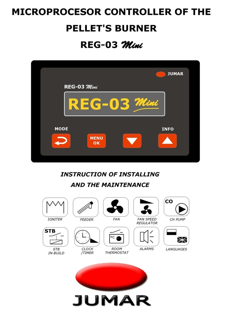
MICROPROCESOR CONTROLLER OF THE
PELLET'S BURNER
REG-03 TFT v1.0
INSTRUCTION OF INSTALLING
AND THE MAINTENANCE
- 1 -
FAN
CO
CH PUMP
STB
STB
IN-BUILD
ºC
ROOM
THERMOSTAT
ALARMS
FAN SPEED
REGULATOR
CLOCK
/TIMER
IGNITER FEEDER
LANGUAGES

JUMAR REG-03TFT
- 2 -

JUMAR REG-03TFT
TABLE OF CONTENTS
SAFETY OF OPERATIONAL USE...........................................................................5
INSTALLATION GUIDANCE.................................................................................5
TECHNICAL DATA...............................................................................................6
THE IMPLEMENTATION.......................................................................................7
THE PRICIPLE OF WORKING...............................................................................7
THE CONNECTION DIAGRAM..............................................................................8
THE DRI ER'S HANDLING................................................................................12
OPERATION CONTROLLER................................................................................14
ALARMS........................................................................................................16
WORKING MODES..........................................................................................18
MENU STRUCTURE..........................................................................................20
CENTRAL HEATING TEMPERATURE SETTINGS.....................................................21
WARM USAGE WATER TEMPERATURE SETTINGS (optio al)...................................21
SETTINGS' TABLES.........................................................................................22
PARAMETERS................................................................................................24
MENU HEATING...........................................................................................24
MENU WUW................................................................................................25
MENU BURNER............................................................................................26
MENU TIMER..............................................................................................28
MENU CLOCK..............................................................................................30
MENU DEVICE.............................................................................................31
MENU SERVICE...........................................................................................31
SYSTEM LOGS............................................................................................32
TERMS OF WARRANTY......................................................................................33
NOTES..............................................................................................................35
- 3 -

JUMAR REG-03TFT
Thanks you fo choosing ou p oduct.
This inst uction should make the installation of the d ive easie and make
you accustomed to the maintenance and the safe using of the device.
Befo e installing please ead the inst uction ca efully and get to know the
functioning of the d ive .
Any questions occu , contact with the JUMAR company.
P.P.U.H JUMAR Jerzy Podhajski
ul. Opawska 112
47-400 Racibórz
tel./fax 32-415-80-39
tel. 32-415-54-24
e-mail: biuro@ju-mar.eu
www.ju-mar.eu
- 4 -

JUMAR REG-03TFT
SAFETY OF OPERATIONAL USE
Before usi g read carefully the i structio .
I stalli g a d co ecti g the regulator should be do e by a professio al staff. All
available safety requireme ts should be take i to co sideratio .
Before switchi g the regulator o , the accuracy of all co ectio s ought to be
checked.
Guara tee proper worki g co ditio s accordi g to the device's specificatio .
INSTALLATION GUIDANCE
Do ot power the device from the same source of power as others devices of high
power without appropriate et filters.
Avoid putti g sig al wires i a direct co tiguity a d i parallel to e ergetic a d
poweri g wires.
Avoid close ess of remotely-co trolled devices, loads of high power devices with
a group or phase regulatio of power a d other devices produci g large
i terfere ce of impulses.
Whe switchi g o the feed mecha ism, remember that i the i stallatio of a
buildi g a breaker or a circuit breaker should exist. This part ought to be ear the
device, easy to reach by the operator a d marked as a device disco ecti g the
mecha ism.
For problems caused by disobeyi g the i structio , the ma ufacturer is ot
respo sible for.
- 5 -

JUMAR REG-03TFT
TECHNICAL DATA
Burner handling: to 500kW *
Sensors: KTY / PT1000 / NTC *
Measurement range: -30 – 120°C / -30 – 400°C / -30 - 250°C *
Measurement resolution: 0.1 °C
Time of measurements: 1 s
Data's reading: TFT display with touch scree 3" or 5" *
Control outputs:
•Ig iter (relay): ~230V 3A (2A)
•Feeder (triac): ~230V 2A (0.8A)
•Feeder 2 (triac): ~230V 2A (0.8A) *
•Air Fa (triac): ~230V 2A (0.8A)
•CH Pump (relay): ~230V 2A (0.8A)
•HUW Pump (relay/triac): ~230V 2A (0.8A) *
•Clea i g system (relay): ~230V 2A (0.8A) *
Protection:
•Temperature (build-i ) STB (80°C-400°C)
•Electric (exter al) Fuse 4A
Inputs:
•Room thermostat: Ope co tact
•Exter al co trol: Ope co tact *
•Fire se sor: Opto eleme t
•Heati g se sor: KTY / PT1000 / NTC *
•Bur er feeder se sor: Bimetal 75°C
•STB se sor: Bimetal (95°C-400°C) *
•Chim ey se sor: PT1000 *
isual signalling:
•LCD scree : Messages, measureme ts, setti gs
•Sou d: Alarms
Power supply: ~110-230 V 50/60Hz 5VA / 10VA *
Working temperature: 5°C - 50°C
* Optional
- 6 -

JUMAR REG-03TFT
THE IMPLEMENTATION
REG – 03TFT co troller is a moder microprocessor device co trolli g the work of
the pellet's bur er. Impleme tatio of adva ced driver's algorithm a d the flame se sor
e sures the simplicity of mai te a ce a d the full automatizatio of the bur i g
process. The usage of a graphic display with touch scree assures a easy a d clear
i teractio betwee the use a d the device. The driver is adapted also to worki g with
the ce tral heati gs pump a d warm usage water pump (optio al). Tha ks to these
fu ctio s, the device ca be used i expa ded i stallatio s of the ce tral heati g
without usi g additio al steeri g devices. The regulator is also equipped with a output
of room thermostat which e ables the cha ge of the fur ace's worki g parameter after
reachi g a particular temperature i the room. To co troller added timer fu ctio s – ow
user ca set heati g time.
THE PRICIPLE OF WORKING
The device's work is based o providi g fuel via steeri g the feeder appropriately
a d the work of a fa which steers the bur i g process. After reachi g a particular
temperature of the heati g water, the driver goes i to the mode of sustai i g the
temperature or switches the bur er completely off. The ig itio of fuel starts
automatically with the help of ig iter which is co ected to this driver. The driver
e ables the co trol of the fur ace's work tha ks to the room thermostat. It is possible
to steer the heati g i relatio to the actual temperature i the room. The regulator is
also equipped with the self-co trol systems (detecti g the malfu ctio of the
temperature's se sors) a d mecha isms mo itori g the fur ace's work preve ti g from
goi g beyo d the ra ge of safety for the i stallatio of the ce tral heati g (STB).
- 7 -

JUMAR REG-03TFT
THE CONNECTION DIAGRAM
The figure above shows a scheme demo strati g co ectio of se sors a d co trolli g
eleme ts to the co troller. Before co ecti g the regulator to etwork, it is ecessary to
check all the co ectio s carefully. O e has to take particular ote of ot placi g ~230V
power supply cables i stead of the se sor. Improper co ectio may perma e tly
damage the microprocessor device.
- 8 -

JUMAR REG-03TFT
CONNECTION DESCRIPTION
Terminal
No. Designation Input/
Output Description
1
2
N
L
i put
i put Power supply co ector
3
4
F1
F2
i put
i put Mai fuse co ector 4A
5
6
L
N
output
output Ig iter co ector
7
8
L
N
output
output Ce tral heati g pump co ector
9
10
L
x
output
x
Clea i g system co ector *
Warm usage water pump co ector *
11
12
L
N
output
output
13
14
L
N
output
output Feeder co ector
15
16
L
N
output
output
I ter al feeder co ector *
Clea i g system co ector *
Warm usage water pump co ector *
17
18
S1
GND
i put
i put
Warm Usage Water se sor co ector *
Chim ey se sor co ector *
19
20
BSTB
GND
i put
i put Bur er feeder se sor co ector (bimetal 75°C - 90°C)
21
22
PL (+)
GND (-)
i put
i put Fire se sor co ector (opto eleme t)
23
24
CH
GND
i put
i put Ce tral heati g se sor co ector
25
26
S1
GND
i put
i put
Room thermostat co ector *
Exter al co trol co ector *
Chim ey se sor co ector *
* depe d a hardware co figuratio
- 9 -

JUMAR REG-03TFT
Terminal
No. Designation Input/
Output Description
1
2
BSTB
GND
i put
i put Bur er feeder se sor co ector (bimetal 75°C - 90°C)
3
4
PL (+)
GND (-)
i put
i put Fire se sor co ector (opto eleme t)
5
6
x
x
7 L output Ig iter co ector
8 L output Air fa co ector
9 L output I ter al feeder co ector *
10 L output Clea i g system co ector *
11 x
12 N output Ig iter co ector
13 N output Air fa co ector
14 N output I ter al feeder co ector *
15 N output Clea i g system co ector *
* depe d a hardware co figuratio
Fire sensor (polarity):
CAUTION!!
Bad co ectio of the se sor causes the weak respo se of the se sor to the flame/fire.
- 10 -
-
+

JUMAR REG-03TFT
I the picture below, illustrates a example of placi g se sors:
Sensor
No. Designation Name Description
1 STB STB
Se sor
STB se sor (securi g se sor) has to be places i
the boiler alo g with the CH se sor.
2 CH CH
Se sor Ce tral heati g water se sor (CH).
3 FEED Bur er
Se sor
The se sor protects the bur er agai st excessive
temperature growth. Bimetal se sor has to
selected accordi g to the bur er.
4 FIRE Fire
Se sor
The flame se sor has to be placed so that it could
detect flame a d heat i the fur ace/boiler. You
should ot subject it to high temperatures. Whe
co ecti g, you have to take ote of polarizatio
of the se sor (+/-).
- 11 -

JUMAR REG-03TFT
THE DRI ER'S HANDLING
After switchi g the driver o , o the LCD scree appears the programme's logo
defi i g the type of the driver a d the ma ufacturer's logo.
After a few seco ds co troller show measureme t pa el. The followi g figure shows a
example of the appeara ce of LCD scree s.
- 12 -
ERSION

JUMAR REG-03TFT
Additio ally, the user is required to set the date of the bur er o the first start. From
that mome t, the warra ty of the co trol device is cou ted.
If some problems with the device or co figuratio will be appear, please co tact with
service. Ma ufacturer's data ca be fou d o the service scree by clicki g o the
ma ufacturer's logo.
- 13 -

JUMAR REG-03TFT
OPERATION CONTROLLER
The mai scree is divided i to pa els: HEATING PANEL, HUW PANEL, BURNER
PANEL. The figure below shows how to switch betwee pa els.
- 14 -

JUMAR REG-03TFT
The last pa el shows the operatio of boiler eleme ts a d the bur er: fa , ig iter,
feeder, pump, values from se sors.
The ico s ca have three differe t colours symbolizi g the work of the eleme t, e.g.
Icon Description
Fu ctio disable.
Fu ctio e able, device is worki g.
Fu ctio e able, device is ot worki g.
- 15 -
IGNITER FEEDER
INTERNAL
FEEDER
AIR FAN
CH
PUMP
CLEANING
SYSTEM
WUW
PUMP
ROOM THERMOSTAT/
EXTERNAL CONTROL
CHIMNEY
SENSOR
FIRE
SENSOR
BURNER
POWER
TEMPERATURE
SENSOR
BURNER
SENSOR
AIRFAN
SPEED

JUMAR REG-03TFT
ALARMS
If the se sor is damaged or it is ot co ected, the temperature display will show a "–-"
image alo g with givi g sou d alarm. The alarm is switched off automatically after
failure removal (co ecti g the se sor or replaci g it with a ew o e). The figure below
visualized a exemplary scree i formi g about missi g se sor or se sor damage:
The alarm will be also activated, if the temperature exceeds safe value (90ºC).
Exceedi g the temperature causes the bur er to stop a d switch i to dampi g mode.
The bur er's operatio is blocked. The display will show the followi g message:
STB alarm has to be reseted ma ually after decreasi g the temperature blow critical
value.
- 16 -

JUMAR REG-03TFT
The co troller also mo itors the temperature of bur er's case. If the temperature will
exceed above pre-set value, the co troller will lau ch the bur er protectio procedures
a d display a message:
The bur er's operatio is blocked duri g alarm. After decreasi g the temperature below
critical, the co troller automatically retur s i to previous state.
- 17 -

JUMAR REG-03TFT
WORKING MODES
The co troller may work i two worki g modes („ON”, „OFF”). The „OFF” mode
activates procedures co ected with the bur er's putti g out i.e. bur i g off a d
clea i g. .
FUNCTIONS
NAME
FUNCTION
DESCRIPTION
STOP Bur er stopped.
FILLING Filli g the feeder.
Filli g stops automatically after about 10 mi utes.
IGNITION Ig itio of pellet. The mode would be automatically cha ged after
detecti g a flame by the se sor.
CLEANING The clea i g of the bur er from he left ashes. The clea i g
fu ctio also as a blow dow before ig itio .
COMPRESSOR Compressor clea i g a bur er (optio al).
WORK Heati g the boiler up to the set temperature. Showi g the actual
power of the bur er.
PAUSE Sustai i g the set temperature (if the bur er's worki g mode is i
the mode of co ti uous work)
BURNING OFF Putti g off the bur er. Active i the STOP mode or i the
temporal worki g mode of the bur er.
STANDBY Sta dby of the bur er for the decli e of the temperature of a
hysteresis (if the bur er's worki g mode is i the temporal mode).
NO PELLET
The driver carries out three trials of ig itio of the pellet. The lack
of flame may be caused by: the lack of the pellet i the co tai er,
whe the big feeder was ot filled with the pellets, the flame's
se sor is dirty or broke .
BURNER ALARM If the temperature of bur er rises over the maximum value, the
driver would activate the procedures of the bur er's protectio .
STB ALARM Boiler overheat alarm. Bur er will be stop. Alarm should be RESET
by user.
- 18 -

JUMAR REG-03TFT
While activati g the driver for the first time, the „OFF” mode is activated. Every ext
time, its status is saved i the regulator's o -volatile memory. Activati g the driver
agai , automatically causes switchi g o of the lately used worki g mode.
I the picture, the way of movi g betwee the particular driver's modes. I the „ON”
mode, the regulator steers the fu ctio s automatically a d depe ds o the parameters
set by the user. I this mode the status of the flame is co sta tly mo itored. The
decli e of the flame activates fu ctio s li ked to the ig itio of the pellet (if the
particular bur er's fu ctio requires it). The driver carries out three trials of ig itio of
the pellet. The lack of flame may be caused by: the lack of the pellet i the co tai er,
whe the big feeder was ot filled with the pellets, the flame's se sor is dirty or broke .
CAUTION!!
The flame's se sor should be cleared regularly. The smudge of dirt may be the reaso of
false i terpretatio of the bur er's status, causi g for example, a higher fuel
co sumptio without full bur i g of the pellet.
- 19 -

JUMAR REG-03TFT
MENU STRUCTURE
The co troller me u is divided i to eight groups: „HEATING”, „HUW”, „BURNER”,
„DE ICE”, „CLOCK”, „TIMER”, „LOGS”, „SER ICE”. The followi g figures show how to
avigate betwee me us.
- 20 -
Table of contents
Other JUMAR Controllers manuals
Popular Controllers manuals by other brands

AMX
AMX NetLinx Integrated Controller NI-2100 installation guide

AKO
AKO AKO-10123 manual

Elsner
Elsner KNX S1E-UP 230V Installation and adjustment manual

Mitsubishi Electric
Mitsubishi Electric MELSEC iQ-F FX5 installation manual

LVS
LVS EPC-THPH installation instructions

Uponor
Uponor Smatrix Base Pro quick guide