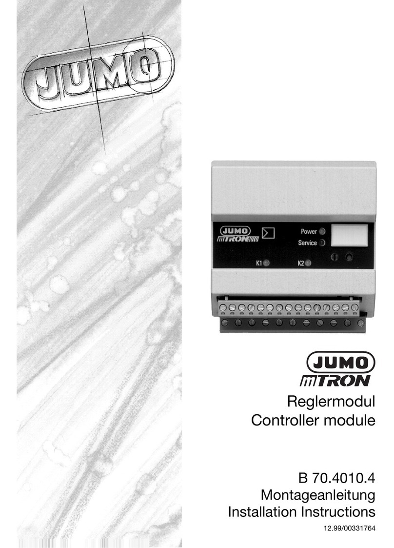
JUMO 709061/8-01-032 User manual

JUMO TYA 201
Single-Phase Thyristor Power Controller
Operating Manual
70906100T90Z001K000
V1.04/EN/00561071
709061/8-01-020
709061/8-01-050
709061/8-01-150
709061/8-01-200
709061/8-01-250
709061/8-01-100
709061/8-01-032

All parameter settings are described in detail in the chapter "Configuration".
This operating overview shows all possible parameters of the device series.
Depending on the order specifications or current configuration, any parameters that are not required are hidden.
EXIT
1
1. W Load monitoring
(Over- or Undercurrent) isset in to Teach in “by Hand”.
2. Code-entry will only appear if, thislevel waslocked previously with a code.
3. Will only appear in the user level
ill only appear if Teach-In for
The user level containsall marked parameters
of the configuration level.
They can be modified during the Operation
without a restart.
Temperature unit
Display contrast
Switch-off Display light
Apply factory settings
Mainsswitch variant
Thyristor control
Operating mode
Subordinate control
Cycle time
Min. ON period
astart
Angle astart
Soft start
Soft start type
Soft start duration
Current limiting
Current limiting value
Resistance limiting
Resistance limit value
Load type Resistance limit
Dual energy management
Current Measuring range
Current range Start
Current range End
Voltage Measuring range
Voltage range Start
Voltage range End
Setpoint input
a- input
a - value
input in the event of an error
value in the event of an error
Maximum output value
Basic load
Limit value monitoring
Limit value Min alarm
Limit value Max alarm
Limit value Hysteresis
Load monitoring
Limit value Load monitoring
Load type
Teach- in type Load monitoring
Load monitoring Teach- in
Mainsvoltage drop monitoring
Changeover phase control, setpoint input
Ext. Current limitation
Ext.Current Limit value
Key lock
Ext. deactvation display light
Control direction Inhibit input
Control direction Binäry input1
Control direction Binäry input2
Output mode, Control direction Binary output
Changing codesfor Manual mode, User level
and Configuration level
Signal type actual value output
Output value
Signal range Start value
Signal range End value
Baud rate, Data format, Device adress,
Min. Response time
Data format, Device adress
PGM
PGM
PGM PGM
PGM
PGM
EXIT
EXIT
PGM
EXIT
EXIT
Measured value
overview
Load voltage
Load current
Power
Load resistance
Output level
Setpoint
Process value
Phase angle width
Supply frequency
Device temperature
Current input
Voltage input
EXIT
PGM
VDN-No.
Order code
Rated voltage
Rated current
Option current meas.
Option P-Control
Interface
Production number
Test-ID
2
2
2
3
Navigation principle
one level
back
one level
lower
decrease value/
parameter down
PGM
EXIT
increase value/
parameter up
Alias-device-adress

V1.04/EN/00561071 [Thyristor Leistungsschalter TYA201] 1
Inhalt
1 Introduction..................................................................................7
1.1 Preface ........................................................................................................ 7
1.2 Typographical conventions ....................................................................... 8
1.2.1 Warning symbols ................................................................................................. 8
1.2.2 Note symbols ....................................................................................................... 9
1.2.3 Performing an action ........................................................................................... 9
1.2.4 Display types ........................................................................................................ 9
1.3 Order details ............................................................................................. 10
1.3.1 Scope of delivery ............................................................................................... 11
1.3.2 Accessories ........................................................................................................ 11
1.3.3 General accessories .......................................................................................... 11
1.4 Brief description ....................................................................................... 12
1.5 Standards, approvals, and conformity ................................................... 13
2 Mounting ....................................................................................15
2.1 Important installation notes .................................................................... 15
2.1.1 Environmental conditions ................................................................................. 16
2.1.2 Filtering and interference suppression ............................................................ 17
2.1.3 Admissible load current depending
on the ambient temperature and the site altitude .......................................... 17
2.1.4 Wall mounting with screws (default) ................................................................ 19
2.1.5 Mounting on DIN rail (accessories) .................................................................. 22
2.2 Dimensions ............................................................................................... 23
2.2.1 Type 709061/X-0X-020-XXX-XXX-XX-25X ....................................................... 23
2.2.2 Type 709061/X-0X-032-XXX-XXX-XX-25X ....................................................... 23
2.2.3 Type 709061/X-0X-050-XXX-XXX-XX-25X ....................................................... 24
2.2.4 Type 709061/X-0X-100-XXX-XXX-XX-25X ....................................................... 24
2.2.5 Type 709061/X-0X-150-XXX-XXX-XX-25X
Type 709061/X-0X-200-XXX-XXX-XX-25X ....................................................... 25
2.2.6 Type 709061/X-0X-250-XXX-XXX-XX-25X ...................................................... 26
2.2.7 Clearances (all types) ........................................................................................ 26
3 Electrical connection ................................................................27
3.1 Plug-in screw terminals with 20 A .......................................................... 27

2 V1.04/EN/00561071 [Thyristor Leistungsschalter TYA201]
Inhalt
3.1.1 Type 709061/X-0X-20-XXX-XXX-XX-25X ......................................................... 27
3.2 Cable lugs and plug-in screw terminals as of 32 A .............................. 28
3.2.1 Type 709063/X-0X-032-XXX-XXX-XX-25X
Type 709063/X-0X-050-XXX-XXX-XX-25X ....................................................... 29
3.2.2 Type 709061/X-0X-100-XXX-XXX-XX-25X ....................................................... 31
3.2.3 Type 709061/X-0X-150-XXX-XXX-XX-25X
Type 709061/X-0X-200-XXX-XXX-XX-25X ....................................................... 32
3.2.4 Type 709061/X-0X-250-XXX-XXX-XX-25X ....................................................... 33
3.3 Connection diagram ................................................................................ 34
3.4 Switch-on sequence ................................................................................ 37
3.4.1 Single-phase operation: phase / N .................................................................. 38
3.4.2 Single-phase operation: phase / phase ........................................................... 39
3.4.3 Star connection with accessible star point (N) ............................................... 40
3.4.4 Open delta connection (six-wire connection) ................................................. 41
3.4.5 Free-running economy circuit with purely resistive loads ............................. 42
3.4.6 Master-slave 3-phase current economy circuit for resistive loads in star/delta
connections, or transformer loads (resistive-inductive) ................................ 43
4 Operation....................................................................................45
4.1 Display after switching on the device .................................................... 45
4.1.1 Display and control elements ........................................................................... 46
4.1.2 Appearance of measured values ...................................................................... 46
4.1.3 Meaning of the displayed measured values .................................................... 48
4.1.4 Appearance in the configuration level ............................................................. 49
4.1.5 Appearance of error messages and special statuses .................................... 49
4.2 Operating level ......................................................................................... 50
4.2.1 Device data ........................................................................................................ 50
4.2.2 Power controller ................................................................................................ 51
4.2.3 Setpoint value configuration ............................................................................ 51
4.2.4 Monitoring .......................................................................................................... 52
5 Configuration .............................................................................55
5.1 Configuration level ................................................................................... 55
5.1.1 Device data ........................................................................................................ 56
Language wizard active................................................................................................... 56
Temperature unit.............................................................................................................. 56

V1.04/EN/00561071 [Thyristor Leistungsschalter TYA201] 3
Inhalt
Display contrast ............................................................................................................... 56
Switch-off......................................................................................................................... 56
Display lighting................................................................................................................. 56
Apply default settings ...................................................................................................... 56
5.1.2 Power controller ................................................................................................ 56
Mains switching variant ................................................................................................... 56
Thyristor control............................................................................................................... 56
Operating mode............................................................................................................... 57
Subordinate control loop ................................................................................................. 58
Cycle time........................................................................................................................ 59
Min. ON period ................................................................................................................ 59
αstart............................................................................................................................... 59
αstart angle..................................................................................................................... 59
Soft start .......................................................................................................................... 59
Soft start type .................................................................................................................. 60
Soft start duration............................................................................................................ 60
Current limiting ................................................................................................................ 61
Current limit value............................................................................................................ 61
Resistance limitation........................................................................................................ 61
Resistance limit value ...................................................................................................... 61
Load type resistance limitation........................................................................................ 61
Dual energy management................................................................................................ 61
5.1.3 Analog inputs ..................................................................................................... 62
Current measuring range................................................................................................. 62
Current measuring range, start........................................................................................ 62
Current measuring range, end......................................................................................... 62
Voltage measuring range................................................................................................. 62
Voltage measuring range, start........................................................................................ 62
Voltage measuring range, end......................................................................................... 62
5.1.4 Setpoint value configuration ............................................................................ 63
Setpoint specification ...................................................................................................... 63
αinput.............................................................................................................................. 63
αinput value .................................................................................................................... 63
Input in the event of an error............................................................................................ 64
Value in the event of an error........................................................................................... 64
Maximum actuating variable............................................................................................ 64
Base load......................................................................................................................... 65
5.1.5 Monitoring .......................................................................................................... 66
> Limit value monitoring .................................................................................................. 66
Min. limit value alarm ....................................................................................................... 66
Max. limit value alarm ...................................................................................................... 66
Limit value hysteresis....................................................................................................... 67
>Load monitoring............................................................................................................. 67
Limit value load monitoring.............................................................................................. 67
Load type load monitoring............................................................................................... 67
Teach-In type load monitoring......................................................................................... 67
>Mains voltage drop monitoring...................................................................................... 67

4 V1.04/EN/00561071 [Thyristor Leistungsschalter TYA201]
Inhalt
>Control loop monitoring................................................................................................. 67
5.1.6 Digital inputs ...................................................................................................... 68
Toggling the operating mode to phase-angle control ..................................................... 68
External toggling of setpoint specification....................................................................... 68
Setpoint specification when toggling............................................................................... 68
Value when toggling......................................................................................................... 68
Ext. current limiting.......................................................................................................... 69
Ext. current limit value ..................................................................................................... 69
Key lock ........................................................................................................................... 69
External switch-off of display lighting.............................................................................. 69
Inhibit input control direction........................................................................................... 69
Control direction, digital input1 ....................................................................................... 70
Control direction, digital input2 ....................................................................................... 70
5.1.7 Digital output ...................................................................................................... 71
Output mode.................................................................................................................... 71
Control direction, digital output ....................................................................................... 72
5.1.8 Analog output ..................................................................................................... 73
Signal type, actual value output ...................................................................................... 73
Value to be output ........................................................................................................... 73
Signal range start value ................................................................................................... 73
Signal range end value .................................................................................................... 73
5.1.9 RS422/485 .......................................................................................................... 73
Baud rate ......................................................................................................................... 73
Data format...................................................................................................................... 73
Device address ................................................................................................................ 73
Min. response time .......................................................................................................... 73
5.1.10 PROFIBUS-DP .................................................................................................... 74
Device address ................................................................................................................ 74
Data format...................................................................................................................... 74
5.1.11 JUMO mTRON T system interface ................................................................... 74
Alias device address........................................................................................................ 74
5.1.12 Changing codes ................................................................................................. 74
Code, manual mode ........................................................................................................ 74
Code, operator level ........................................................................................................ 74
Code, config. level ........................................................................................................... 74
5.2 Configuration example ............................................................................ 75
6 Special device functions..........................................................77
6.1 Detection of load faults ........................................................................... 77
6.1.1 Teach-In .............................................................................................................. 79
6.2 Manual mode ............................................................................................ 80
6.2.1 Setpoint specification in manual mode ........................................................... 80

V1.04/EN/00561071 [Thyristor Leistungsschalter TYA201] 5
Inhalt
6.2.2 Configuring Teach-In (prerequisite for Teach-In in manual mode) ............... 80
6.2.3 Performing Teach-In in manual mode ............................................................. 81
6.3 Setpoint specification via potentiometer .............................................. 82
6.4 Dual energy management ....................................................................... 82
6.5 Subordinate control loop ......................................................................... 84
6.5.1 Closed control loop without subordinate control ........................................... 84
6.5.2 Closed control loop with subordinate control ................................................ 85
6.6 Resistance limitation (r-control) ............................................................. 90
6.7 Current limiting ........................................................................................ 91
6.8 αstart ........................................................................................................ 92
6.9 Monitoring of the mains voltage drop .................................................... 92
6.10 Firing pulse inhibit .................................................................................... 92
6.11 Thyristor control logic (switch) ............................................................... 93
7 Setup program ...........................................................................95
7.1 Hardware .................................................................................................. 95
7.2 Compatible operating systems ............................................................... 95
7.3 Installation ................................................................................................ 96
7.4 Program start ........................................................................................... 98
7.5 Forgotten the code? ................................................................................ 99
7.6 Changing the language of the device texts ......................................... 100
8 Error messages and alarms....................................................101
8.1 Binary signal for collective fault ........................................................... 105
8.2 Replacing a defective semiconductor fuse ......................................... 106
8.2.1 Accessories: semiconductor fuses ................................................................ 107
8.2.2 Semiconductor fuses type 709061/X-0X-20... ............................................... 107
8.2.3 Semiconductor fuses type 709061/X-0X-32... ............................................... 108

6 V1.04/EN/00561071 [Thyristor Leistungsschalter TYA201]
Inhalt
9 What to do, if ...........................................................................111
10 Technical data..........................................................................113
10.1 Voltage supply, load current ................................................................. 113
10.2 Galvanic isolation ................................................................................... 113
10.3 Analog inputs ......................................................................................... 114
10.4 Analog output (actual value output) ..................................................... 114
10.4.1 Display and measuring accuracy ................................................................... 114
10.5 Digital inputs .......................................................................................... 114
10.6 Digital output (fault signal output) ........................................................ 114
10.7 General specifications ........................................................................... 115
10.8 Approvals / approval marks .................................................................. 117
11 Certificates...............................................................................119
11.1 UL ............................................................................................................ 119
11.2 China RoHS ............................................................................................ 121

V1.04/EN/00561071 [Thyristor Power Switch TYA 201] 7
1 Introduction
1.1 Preface
Read this operating manual before putting the device into service.
This operating manual is valid from device software version [256.02.01].
Keep the operating manual in a place that is accessible to all users at all times.
Your comments are appreciated and may assist us in improving this operating
manual.
Phone: +49 661 6003-727
Fax: +49 661 6003-508
Service hotline For technical questions
Phone support in Germany:
Phone: +49 661 6003-9135
Fax: +49 661 6003-881899
Email: [email protected]
Austria:
Phone: +43 1 610610
Fax: +43 1 6106140
Email: [email protected]
Switzerland:
Phone: +41 1 928 24 44
Fax: +41 1 928 24 48
Email: [email protected]
A
The power controller produces the power that is needed at the analog input or
in manual mode. Safety systems independent of the power controller must be
installed. They should safely switch off the subsequent heating process in the
event of excess temperatures.
A
The power controller may only be operated using original JUMO semiconduc-
tor fuses.
In the event of replacement, please check that the correct spare part has been
used.
H
All necessary settings are described in this operating manual.
Manipulations not described in the operating manual or expressly forbidden
will jeopardize your warranty rights.
If you have any problems, please contact the nearest branch office or the head
office.

1 Introduction
8 V1.04/EN/00561071 [Thyristor Power Switch TYA 201]
1.2 Typographical conventions
1.2.1 Warning symbols
Caution
Warning
ESD
Dangerous volt-
age
Hot
surface,
fire hazard
E
When accessing the inner parts of the device and returning device plug-in
units, modules, or components, please observe the regulations according to
DIN EN 61340-5-1 and DIN EN 61340-5-2 "Protection of electronic devices
from electrostatic phenomena". Use only ESD packaging for shipment.
Please note that we cannot accept any liability for damage caused by ESD.
ESD=Electrostatic Discharge
V
This character is used if personal injury may result from failure to
follow instructions correctly or not at all!
A
This symbol is used when damage to devices or data may result
from failure to follow instructions correctly or not at all!
E
This character is used if precautionary measures must be taken
when handling electrostatically sensitive components.
This symbol is used if dangerous voltages will cause an electric shock
in the event of contact with live parts.
This symbol is used if burns can result from touching a hot surface.
Do not install any heat-sensitive components or devices close to the
power controller.

V1.04/EN/00561071 [Thyristor Power Switch TYA 201] 9
1 Introduction
1.2.2 Note symbols
Note
Reference
Footnote
1.2.3 Performing an action
Action
instruction
Vital text
Command se-
quence
1.2.4 Display types
Keys
H
This symbol is used to draw your attention to a particular issue.
v
This symbol refers to further information in other manuals, chap-
ters, or sections.
abc1Footnotes are remarks that refer to specific parts of the text. Foot-
notes consist of two parts:
An identification marking in the text, and the footnote text itself.
The markers in the text are arranged as continuous superscript
numbers.
hPlug in the
connector
This symbol marks the description of a required action. The
individual steps are marked by this asterisk
V
READ THE DOCUMENTATION!
This symbol, which is attached to the device, indicates that the as-
sociated device documentation must be observed. This is nec-
essary in order to recognize the nature of the potential danger and
take the necessary measures to prevent it.
Config. level rPower controller r
Operating mode
Small arrows between words are designed
to make it easier to find parameters in the
configuration level.
Keys are displayed as symbols or text.
Key combinations are represented by a plus sign.

1 Introduction
10 V1.04/EN/00561071 [Thyristor Power Switch TYA 201]
1.3 Order details
The nameplate is affixed to the right-hand side of the housing.
(1) Basic type
709061 TYA 201 single-phase thyristor power controller
(2) Version
8 Standard with default settings
9 Customer-specific programming according to specifications
(3) National language of device texts
01 German (default setting)
02 English
03 French
(4) Load current
020 AC 20 A
032 AC 32 A
050 AC 50 A
100 AC 100 A
150 AC 150 A
200 AC 200 A
250 AC 250 A
(5) Subordinate control loop (see note below)
100 U, U 2
010 I, I 2 (can be set to U, U2)
001 P (can be set to I, I2or U, U2)
(6) Load voltagea
024 AC 24 V -20 ... +15 %, 48 ... 63 Hz
042 AC 42 V -20 ... +15 %, 48 ... 63 Hz
115 AC 115 V -20 ... +15 %, 48 ... 63 Hz
230 AC 230 V -20 ... +15 %, 48 ... 63 Hz
265 AC 265 V -20 ... +15 %, 48 ... 63 Hz
400 AC 400 V -20 ... +15 %, 48 ... 63 Hz
460 AC 460 V -20 ... +15 %, 48 ... 63 Hz
500 AC 500 V -20 ... +15 %, 48 ... 63 Hz
(7) Interface
00 None
54 RS485/422
64 PROFIBUS-DP
84 JUMO mTRON T system interface or EtherCAT
(8) Extra code
252
Relay (changeover contact) 3 A
257 Optocouplerb
(1) (2) (3) (4) (5) (6) (7) (8)
/-----/Order code
709061 / 8 - 01 - 100 - 100 - 400 - 00 / 252 Order example
a.Load voltage = Voltage supply for control electronics (always select phase voltage L1-L2 from the three-phase system for free-running
economy circuits)
b.Enables energy meter
Note:
Subordinate control loop U2, code 100: voltage control
Subordinate control loop I2, code 010: enables voltage control, current control, partial load failure detection, dual energy manage-
ment and current limiting, and energy meter
Subordinate control loop P, code 001: enables voltage control, current control, power control, partial load failure detection, dual
energy management, current limiting, r-control and energy meter
At a load current of 250 A, observe voltage supply for fan!
vChapter 3.2.4 "Type 709061/X-0X-250-XXX-XXX-XX-25X"

V1.04/EN/00561071 [Thyristor Power Switch TYA 201] 11
1 Introduction
1.3.1 Scope of delivery
1.3.2 Accessories
1.3.3 General accessories
Semiconductor
fuses A semiconductor fuse is fitted in the power controller to protect the thyristor
module. The "Fuse LED" lights up red in the event of a fault.
vChapter 8.2 "Replacing a defective semiconductor fuse"
1 operating manual
1 thyristor power controller in the version ordered
Item Part no.
Setup program 709061 (TYA 201) 00544869
USB cable A-connector B-connector 3 m 00506252
Installation kits:
Installation kit for DIN rail 20 A TYA 201 00555169
Installation kit for DIN rail 32 A TYA 201 00555526
Installation kit for DIN rail 50 A TYA 201 00600095
Item Load current
Inom. = IN
Part no.
Super fast semiconductor fuse 40 A IN= 20 A 00513108
Super fast semiconductor fuse 80 A IN= 32 A 00068011
Super fast semiconductor fuse 80 A IN= 50 A 00068011
Super fast semiconductor fuse 160 A IN= 100 A 00081801
Super fast semiconductor fuse 350 A IN= 150 A 00083318
Super fast semiconductor fuse 550 A IN= 200 A 00371964
Super fast semiconductor fuse 550 A IN= 250 A 00371964

1 Introduction
12 V1.04/EN/00561071 [Thyristor Power Switch TYA 201]
1.4 Brief description
Device The JUMO TYA 201 is an enhancement to JUMO power controller technology.
The microprocessor-controlled power controller shows all parameters on a
display with background lighting and is operated using 4 keys at the front.
Application Thyristor power controllers are used where larger resistive and inductive loads
have to be switched (e.g. in industrial furnace construction and plastics pro-
cessing). The thyristor power controller consists of two anti-parallel switched
thyristors, the insulted heat sink, and the control electronics.
Mounting All thyristor power controllers up to a load current of 32 A can be either
clipped to a 35 mm mounting rail or fitted to the wall on a mounting plate. De-
vices with a load current greater than 32 A can only be mounted on the wall.
Operating
modes The keypad or setup program is used to select the phase-angle operation
mode with adjustable current limiting, burst-firing operation, or half-wave op-
eration.
In burst-firing mode, the phase angle of the first half-wave can be cut so that
transformer loads can also be operated. In phase-angle operation mode, the
phase angle specified by the controller is slowly reduced, starting from 180
degrees, in order to avoid high inrush currents (soft start).
Users are able to specify a base load or, depending on the device type, select
current limiting or resistance limitation for the load.
Load types All resistive loads through to inductive loads are permitted.In the case of trans-
former loads, the nominal induction of 1.2 tesla must not be exceeded (value
is 1.45 T in the case of mains overvoltage).
Subordinate
control loop Depending on the device type, U, U2, I, I2, or P controls are available as subor-
dinate control loops. Variations in the mains voltage therefore have no effect
on the control-loop regulation during operation.
Standards The thyristor power controllers comply with VDE 0160 5.5.1.3 (5/88) and VDE
0106 Part 100 (3/83). The devices must be grounded as specified by the re-
sponsible energy supplier.
Advantages - Teach-In function for the detection of partial load failure
- Network load optimization through dual energy management
- Transmission of the setup data is possible even without voltage supply to
the device (power supply via USB port)
-Energymeter

V1.04/EN/00561071 [Thyristor Power Switch TYA 201] 13
1 Introduction
1.5 Standards, approvals, and conformity
Device properties are inspected on the basis of the Low Voltage Directive DIN
EN 50178.
The EMC Directive is inspected on the basis of DIN EN 61326-1.
Standard
Electrical connection DIN VDE 0100
Protection type IP20 built-in devic-
es
DIN EN 60529
Climatic ambient conditions Class 3K3
Air temperature and rel. humidity DIN EN 60721-3-3
Storage temperature class 1K5 DIN EN 60721-3-1
Operating conditions
Pollution degree
Overvoltage category
DIN EN 50178
2
III
Test voltages DIN EN 50178
Residual current circuit breaker DIN EN 50178
Electromagnetic compatibility
Interference emission
Interference immunity
DIN EN 61326-1
Class A- For industrial applications only
Industrial requirements
Mechanical tests:
Vibration test 3M2
Toppling test class 2M1
DIN EN 60068-2-6, DIN EN 60721-3-3
DIN EN 60068-2-31, DIN EN 60721-3-2
Labels, identification marking DIN EN 50178, DIN EN 61010-1
Approvals Standard Type
UL 508 (Category NRNT), pollution degree 2
C22.2 NO. 14-10 Industrial Control Equip-
ment (Category NRNT7)
709061/X-XX-020-...
Load current 20 A
UL 508 (Category NRNT)
C22.2 NO. 14-10 Industrial Control Equip-
ment (Category NRNT7)
709061/X-XX-032...
709061/X-XX-050...
709061/X-XX-100...
709061/X-XX-150...
709061/X-XX-200...
709061/X-XX-250...
Load current
32 to 250 A
Can be used for current circuits with a short-circuit current capacity of
≤100 kA (the admissible mains voltage must correspond to the nominal voltage of
the thyristor controller).
For plant protection, a fuse up to class RK5 may be used.
CE conformi-
ty
Low Voltage Directives 2006/95/EC
Marking Directives 93/68/EEC
EMC Directives 2004/108/EC
Conformity Standard
RoHS 2002/95/EC

V1.04/EN/00561071 [Thyristor Power Switch TYA 201] 15
2 Mounting
2.1 Important installation notes
Safety
regulations kThe choice of cable material, the installation, and the electrical connection
of the device must conform to the requirements of VDE 0100 "Regulations
on the Installation of Power Circuits with Nominal Voltages below AC
1000 V" or the appropriate local regulations.
kThe electrical connection must only be carried out by qualified personnel.
kAn isolating switch should be wired between the voltage supply and the de-
vice to be able to disconnect the device from the voltage supply on all
poles prior to accessing the inner parts of the device.
kInside the device, safety clearances meet the requirements for double insu-
lation.
When mounting the connecting cable, ensure that the cables are fitted ac-
cording to regulations and that the safety clearances are maintained.
Fuse protection kFuse protection of the voltage supply in accordance with the VDE regula-
tions must be installed when wiring the voltage supply in the power section.
The supply can also be protected with a circuit-breaker in the supply lead.
The circuit-breaker must correspond to the power consumption of the pow-
er controller.
kThe connecting cables used for the terminals U1, U2, N/L2, V, and L1 must
have an electric strength of AC 500 V.
kFor UL applications, the fuse for the supply protection of the control elec-
tronics must be between 2 A and a maximum of 5 A. This also applies to
the fan connection.
kA semiconductor fuse is installed to protect the power controller in the
event of a ground fault. In the event of a defect, these may only be replaced
with original JUMO semiconductor fuses.
vChapter 8.2 "Replacing a defective semiconductor fuse"
Wiring Control cables (SELV potential) must be routed so that they are isolated from
cables with mains voltage potential. For supply protection, fuses (e.g. 2 A,
Neozed type) must also be installed in the control circuit.
PE connection hA direct protection conductor connection must be provided between the
power controller and the PE conductor of the supply network. Connection
takes place at the PE connection terminal.
The cross section of the PE conductor must be at least as large as the cross
section of the voltage supply cables in the power section. In the event that the
protective conductor is not a component of the supply lead or its encasement,
the selected conductor cross section may not be less than 2.5 mm2(for me-
chanical protection) or not less than 4 mm2(if the protection conductor is not
protected mechanically).
vSee VDE 0100 Part 540
V

2 Mounting
16 V1.04/EN/00561071 [Thyristor Power Switch TYA 201]
Check hThat the data on the nameplate (rated load voltage, load current) corre-
sponds to the data for the plant.
hThat the rotary electrical field has clockwise phasing if the economy circuit
configuration is used.
hThat the configuration of the analog inputs, for example, corresponds to the
wiring.
hThe analog input for the default setpoint specification in "Master-slave op-
eration" only needs to be connected to the master. The slave receives its in-
formation via the 1:1 patch cable.
However, the slave power controller can be disconnected separately by
means of its own inhibit input.
Load connec-
tion hThe electronic switch (2 anti-parallel thyristors) is located between the U1
and U2 terminals.
hWhere possible, load cables and cables for control inputs should be routed
so that they are isolated.
hConnect the mains voltage - thyristor power controller - load in accordance
with the connection diagram and check.
Phasing The voltage supply of the control electronics and the load voltage
must have the same phase.
Control inputs The terminal strips for control connections (inputs and outputs) have been laid
out for safe isolation from the mains voltage (SELV). To prevent the safe isola-
tion from being impaired, ensure that all connected current circuits are also
safely isolated. The required auxiliary supplies must be SELV voltages.
2.1.1 Environmental conditions
Incorrect use The device is not suitable for installation in potentially explosive areas.
Mounting site The power controller must be installed in a fire-proof control cabinet.
The cabinet should be vibration-free, free from aggressive media, and free
from dust to prevent the ventilation slots from becoming blocked.
Climatic
conditions - Relative humidity: 5 to 85 %, no condensation (3K3 according to EN 60721)
- Ambient temperature range: 0 to 45 °C (3K3 according to EN 60721-3-3)
- Storage temperature range: -30 to +70 °C class 1K5
Avoid additional
sources of heat - Ensure that the ambient temperature at the installation site is not increased
by other sources of heat or heat accumulation.
- Do not mount the power controller too close to the heating process (fur-
nace)
- Avoid direct sunlight.
Power loss Occurs as waste heat on the power controller's heat sink and must be dissi-
pated at the mounting site (e.g. in the control cabinet) in accordance with the
climatic conditions.

V1.04/EN/00561071 [Thyristor Power Switch TYA 201] 17
2 Mounting
2.1.2 Filtering and interference suppression
To prevent radio-frequency interference, generated with a soft start in phase-
angle operation for example, electrical apparatus and plants must have inter-
ference suppression implemented.
The control electronics of the thyristor power controller comply with the EMC
requirements of EN 61326.
However, electrical modules such as thyristor power controllers do not have
any purpose by themselves. They only serve as a component function within a
plant.
Where applicable, the power controllers's entire load circuit must also have
suitable interference suppression filters fitted by the plant provider.
There are a number of specialist companies that provide appropriate ranges of
interference suppression filters to deal with any interference problems. These
filters are normally supplied as complete modules that are ready to be con-
nected.
2.1.3 Admissible load current depending
on the ambient temperature and the site altitude
Ambient tem-
perature
45 50 60
75
20
200
T/°C
150
Load current in A
Reduction at a temperature of 45 °C:
2 %/kelvin 70 %
250
100
50

2 Mounting
18 V1.04/EN/00561071 [Thyristor Power Switch TYA 201]
Site altitude In the case of air cooling, it must be noted that the effectiveness of the cooling
is reduced as the site altitude increases. As a result, the ampacity of the thyris-
tor power controller decreases with such a cooler as the site altitude increas-
es, as shown in the diagram.
A
Destruction through overheating:
In the event of operation at maximum load current over an extended period,
the heat sink and its surroundings heat up.
For this reason, at ambient temperatures above 45 °C, the maximum load cur-
rent must be reduced as shown in the image, as the thyristor module would
otherwise be destroyed.
The device temperature shown on the display may not exceed 100 °C.
At a device temperature of >100 °C, the message "Warning - high tempera-
ture" is displayed.
At a device temperature of >105 °C, the output level is gradually reduced by
10 % of the nominal current each time the temperature increases by one de-
gree.
At a device temperature of >115 °C, the power controller is completely
switched off.
vChapter 8 "Error messages and alarms"
1000 2000
40
20
100
site altitude in m
above sea level
80
Ampacity in %
91,4%
60
3000 4000 5000
Reduction over 1000m above sea level: 0,86 %/100m
This manual suits for next models
7
Table of contents
Other JUMO Control Unit manuals