manuals.online logo
Brands
  1. Home
  2. •
  3. Brands
  4. •
  5. Zennio
  6. •
  7. Control Unit
  8. •
  9. Zennio ZVPCB1MB User manual

Zennio ZVPCB1MB User manual

GetFace IP
Surface installation - Frame - 1 module –nickel/black
ZVP-CB1M / ZVPCB1MB Assembly instructions
© Zennio Avance y Tecnología S.L. Ed. 3 For more info www.zennio.com Page 1/ 1
ASSEMBLY OF THE FRAME
1 Please remove the additional module from the enclosure
and place the metallic auxiliary parts supplied with the frame.
2 Place the additional module enclosure correctly levelled on
the wall and drill two holes for the expanding plugs. Recover the
cables and fix the enclosure with the screws (included).
3 Connect the bus to the additional module.
4 Fix the additional module with the supplied screws.
5 Place the frame.
6 Fix the frame by using the supplied Allen key.
Note: It is recommended to install the backplate (ZVP-BPLA1) if the wall surface irregularity is greater than 0.5mm.
Dimensions: 128 x 106.5 x 27.5 mm
GetFace IP
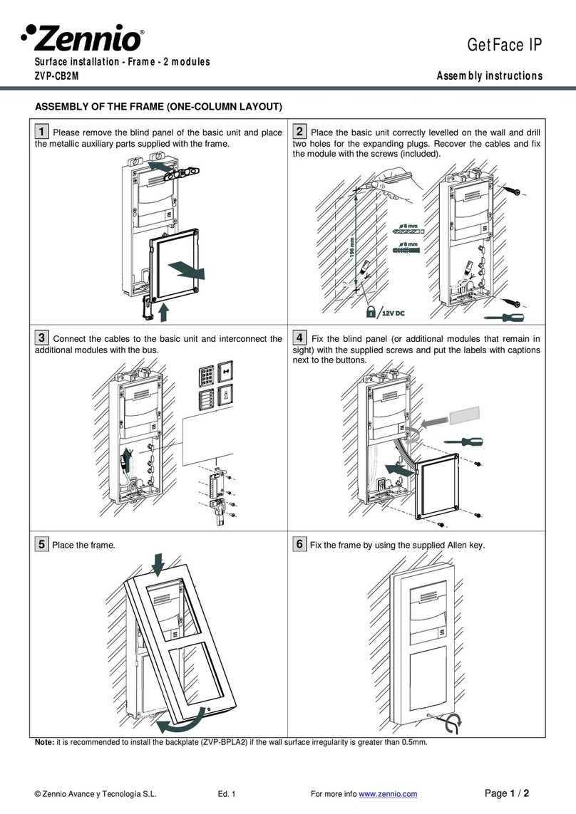
Surface installation - Frame - 2 modules –nickel/black
ZVP-CB2M / ZVPCB2MB Assembly instructions
© Zennio Avance y Tecnología S.L. Ed. 3 For more info www.zennio.com Page 1/ 2
ASSEMBLY OF THE FRAME (ONE-COLUMN LAYOUT)
1 Please remove the blind panel of the basic unit and place
the metallic auxiliary parts supplied with the frame.
2 Place the basic unit correctly levelled on the wall and drill
two holes for the expanding plugs. Recover the cables and fix
the module with the screws (included).
3 Connect the cables to the basic unit and interconnect the
additional modules with the bus.
4 Fix the blind panel (or additional modules that remain in
sight) with the supplied screws and put the labels with captions
next to the buttons.
5 Place the frame.
6 Fix the frame by using the supplied Allen key.
Note: it is recommended to install the backplate (ZVP-BPLA2) if the wall surface irregularity is greater than 0.5mm.
Dimensions:
232 x 106.5 x 27.5 mm
© Zennio Avance y Tecnología S.L. Ed. 3 For more info www.zennio.com Page 2/ 2
ASSEMBLY OF THE FRAME (MULTIPLE-COLUMN LAYOUT)
1 Please remove the blind panels and the additional
modules. After that, assemble the additional module enclosures
by opening the gaps previously. Then, fix the assembly by using
the supplied parts and screws. Place the metallic parts supplied
with the frame.
2 Place the left assembly correctly levelled on the wall and
drill two holes for the expansive plugs. Recover the cables and
fix the module with the screws (included).
3 Place the right assembly on the wall by using the T-shape
parts. Mark the position of the holes, drill them and afterwards
place an expansive plug inside them.
4 Fix the right assembly to the wall with screws. Make the
connections of the basic unit and prepare the additional
modules. Pass the bus cable through the gaps.
5 Interconnect the additional modules with the bus as
indicated in the schema and then fix the additional modules with
screws.
6 Place the frames and fix them by using the supplied Allen
key.
Note: it is recommended to install the backplate (ZVP- BP2W2H) if the wall surface irregularity is greater than 0.5mm.
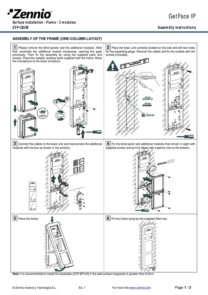
GetFace IP
Surface installation - Frame - 3 modules –nickel/black
ZVP-CB3M / ZVPCB3MB Assembly instructions
© Zennio Avance y Tecnología S.L. Ed. 3 For more info www.zennio.com Page 1/ 2
ASSEMBLY OF THE FRAME (ONE-COLUMN LAYOUT)
1 Please remove the blind panels and the additional modules. After
that, assemble the additional module enclosures, opening the gaps
previously. Then fix the assembly by using the supplied parts and
screws. Place the metallic auxiliary parts supplied with the frame. Move
the microphone to the lower enclosure.
2 Place the basic unit correctly leveled on the wall and drill two holes
for the expanding plugs. Recover the cables and fix the module with the
screws (included).
3 Connect the cables to the basic unit and interconnect the additional
modules with the bus as shown in the schema.
4 Fix the blind panel and additional modules that remain in sight with
supplied screws and put the labels with captions next to the buttons.
5 Place the frame.
6 Fix the frame using by the supplied Allen key.
Note: it is recommended to install the backplate (ZVP-BPLA3) if the wall surface irregularity is greater than 0.5mm.
Dimensions:
337 x 106.5 x 27.5 mm
© Zennio Avance y Tecnología S.L. Ed. 3 For more info www.zennio.com Page 2/ 2
ASSEMBLY OF THE FRAME (MULTIPLE-COLUMN LAYOUT)
1 Please remove the blind panels and the additional modules. After
that, assemble the additional module enclosures by opening the gaps
previously. Then, fix the assembly by using the supplied parts and
screws. Place the metallic parts supplied with the frame. Move the
microphone to the lower enclosure.
2 Place the left assembly correctly leveled on the wall and drill two
holes for the expansive plugs. Recover the cables, place the bus and fix
the left assembly with the screws (included).
3 Place the right assembly on the wall by using the T-shape parts.
Mark the position of the holes, drill them and afterwards place
expansive plugs inside.
4 Fix the right assembly to the wall with screws. Make the
connections of the basic unit and prepare the additional modules. Pass
the bus cable through the gaps.
5 Interconnect the additional modules with the bus as indicated in the
schema and then fix the additional modules with the screws.
6 Place the frames and fix them by using the supplied Allen key.
Note: it is recommended to install the backplate (ZVP-BP2W3H, ZVP- BP3W3H) if the wall surface irregularity is greater than 0.5mm.

This manual suits for next models

1

Other Zennio Control Unit manuals

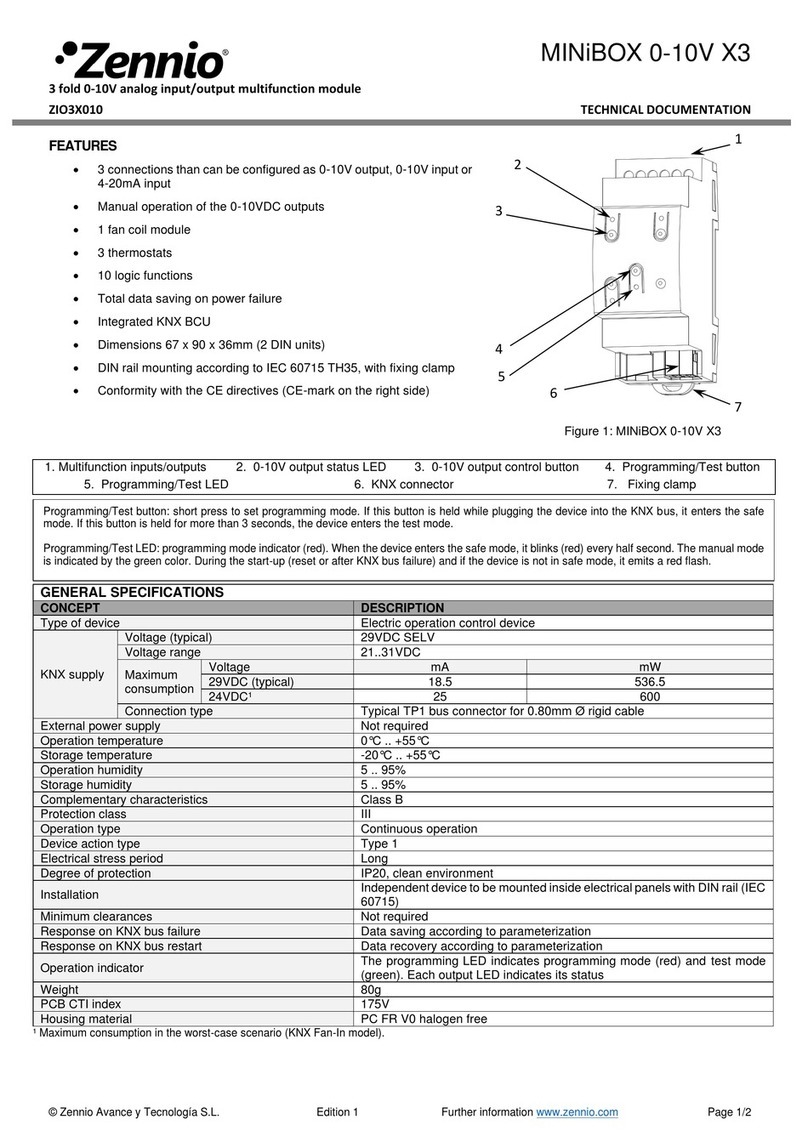
Zennio MINiBOX 0-10V X3 Guide

Zennio

Zennio MINiBOX 0-10V X3 Guide

Zennio GetFace IP ZVP-CB3M User manual

Zennio

Zennio GetFace IP ZVP-CB3M User manual

Zennio KLIC-DI User manual

Zennio

Zennio KLIC-DI User manual

Zennio MAXinBOX FC Guide

Zennio

Zennio MAXinBOX FC Guide

Zennio ZVP-CB2M User manual

Zennio

Zennio ZVP-CB2M User manual

Zennio Analog User manual

Zennio

Zennio Analog User manual

Zennio GetFace IP User manual

Zennio

Zennio GetFace IP User manual

Popular Control Unit manuals by other brands

Hitachi HX-RIO3 Series user manual

Hitachi

Hitachi HX-RIO3 Series user manual

Victron energy Smart BMS CL 12/100 manual

Victron energy

Victron energy Smart BMS CL 12/100 manual

Nibe VVM 320 user manual

Nibe

Nibe VVM 320 user manual

Timotion TC15P Series user manual

Timotion

Timotion TC15P Series user manual

Aeroflex 3035C operating manual

Aeroflex

Aeroflex 3035C operating manual

ARMTEL ARMT.665200.104UM user manual

ARMTEL

ARMTEL ARMT.665200.104UM user manual

CE Tech 5535 installation guide

CE Tech

CE Tech 5535 installation guide

Grinnell F470 manual

Grinnell

Grinnell F470 manual

V2 CITY2+ manual

V2

V2 CITY2+ manual

White Rodgers 11B18 installation instructions

White Rodgers

White Rodgers 11B18 installation instructions

ARM ARM1136JF-S Application note

ARM

ARM ARM1136JF-S Application note

Pfeiffer Vacuum EVC 116 M operating manual

Pfeiffer Vacuum

Pfeiffer Vacuum EVC 116 M operating manual

Quectel RG50-Q Series user guide

Quectel

Quectel RG50-Q Series user guide

Beyerdynamic Quinta CU Features and specifications

Beyerdynamic

Beyerdynamic Quinta CU Features and specifications

KLINGER SCHÖNEBERG INTEC Series operating instructions

KLINGER SCHÖNEBERG

KLINGER SCHÖNEBERG INTEC Series operating instructions

Victaulic I-769N Installation, Maintenance, and Testing Manual

Victaulic

Victaulic I-769N Installation, Maintenance, and Testing Manual

WAGO 750-624/040-00 Series manual

WAGO

WAGO 750-624/040-00 Series manual

Thermomax MASTERLINK manual

Thermomax

Thermomax MASTERLINK manual

manuals.online logo
manuals.online logoBrands
  • About & Mission
  • Contact us
  • Privacy Policy
  • Terms and Conditions

Copyright 2025 Manuals.Online. All Rights Reserved.