JUMO variTRON 500 User manual

70500207T92Z001K000
V1.00/EN/00768869/2023-03-30
JUMO variTRON 500
Automation system
PROFINET interface description


Contents
Contents
1 Introduction . . . . . . . . . . . . . . . . . . . . . . . . . . . . . . . . . . . . . . . . . . . . . . . . . 5
1.1 Warning symbols. . . . . . . . . . . . . . . . . . . . . . . . . . . . . . . . . . . . . . . . . . . . . . . . . . . . . . . . . .5
1.2 Note symbols . . . . . . . . . . . . . . . . . . . . . . . . . . . . . . . . . . . . . . . . . . . . . . . . . . . . . . . . . . . .5
1.3 Notes on trademark . . . . . . . . . . . . . . . . . . . . . . . . . . . . . . . . . . . . . . . . . . . . . . . . . . . . . . .5
2 Compatibility and system requirements . . . . . . . . . . . . . . . . . . . . . . . . . . 7
2.1 Certification . . . . . . . . . . . . . . . . . . . . . . . . . . . . . . . . . . . . . . . . . . . . . . . . . . . . . . . . . . . . . .7
2.2 PROFINET IO and Ethernet standard services . . . . . . . . . . . . . . . . . . . . . . . . . . . . . . . . . .7
2.3 Requirements for hardware, software, and cabling . . . . . . . . . . . . . . . . . . . . . . . . . . . . . . .7
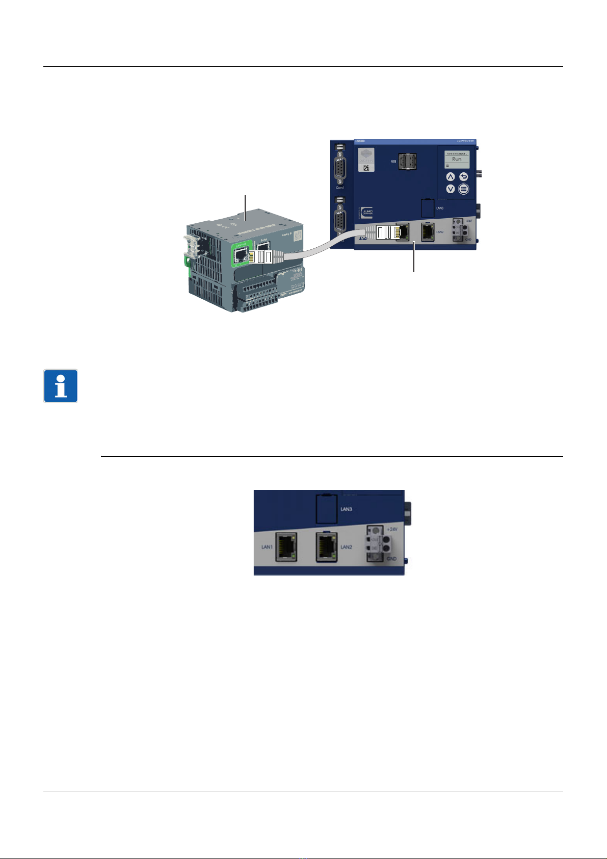
3 Electrical connection . . . . . . . . . . . . . . . . . . . . . . . . . . . . . . . . . . . . . . . . . 9
4 The GSDML file . . . . . . . . . . . . . . . . . . . . . . . . . . . . . . . . . . . . . . . . . . . . . . 11
4.1 General information . . . . . . . . . . . . . . . . . . . . . . . . . . . . . . . . . . . . . . . . . . . . . . . . . . . . . . .11
4.2 Module description . . . . . . . . . . . . . . . . . . . . . . . . . . . . . . . . . . . . . . . . . . . . . . . . . . . . . . . .11
4.2.1 Module concept. . . . . . . . . . . . . . . . . . . . . . . . . . . . . . . . . . . . . . . . . . . . . . . . . . . . . . . . . . .11
4.2.2 Modules . . . . . . . . . . . . . . . . . . . . . . . . . . . . . . . . . . . . . . . . . . . . . . . . . . . . . . . . . . . . . . . .12
5 Project planning . . . . . . . . . . . . . . . . . . . . . . . . . . . . . . . . . . . . . . . . . . . . . 15
5.1 Project integration of JUMO IO devices in CODESYS®. . . . . . . . . . . . . . . . . . . . . . . . . . . .15
5.2 Configuring the JUMO IO device . . . . . . . . . . . . . . . . . . . . . . . . . . . . . . . . . . . . . . . . . . . . .17
5.2.1 Network settings . . . . . . . . . . . . . . . . . . . . . . . . . . . . . . . . . . . . . . . . . . . . . . . . . . . . . . . . . .17
5.2.2 Configuration in CODESYS® (using the setup program) . . . . . . . . . . . . . . . . . . . . . . . . . . .18
5.2.3 Device information . . . . . . . . . . . . . . . . . . . . . . . . . . . . . . . . . . . . . . . . . . . . . . . . . . . . . . . .25
5.3 Project integration of JUMO IO device into IO controller . . . . . . . . . . . . . . . . . . . . . . . . . . .26
6 Error messages and status information . . . . . . . . . . . . . . . . . . . . . . . . . . 35
6.1 Error messages. . . . . . . . . . . . . . . . . . . . . . . . . . . . . . . . . . . . . . . . . . . . . . . . . . . . . . . . . . .35
6.2 Error message in the setup program . . . . . . . . . . . . . . . . . . . . . . . . . . . . . . . . . . . . . . . . . .35
6.3 Status information . . . . . . . . . . . . . . . . . . . . . . . . . . . . . . . . . . . . . . . . . . . . . . . . . . . . . . . . .36

Contents

5
1 Introduction
1 Introduction
1.1 Warning symbols
DANGER!
This symbol indicates that personal injury from electrocution may occur if the appropriate precaution-
ary measures are not taken.
WARNING!
This symbol in connection with the signal word indicates that personal injury may occur if the respective
precautionary measures are not carried out.
CAUTION!
This symbol in connection with the signal word indicates that material damage or data loss will occur
if the respective precautionary measures are not taken.
CAUTION!
This symbol indicates that components could be destroyed by electrostatic discharge (ESD = Electro
Static Discharge) if the respective cautionary measures are not taken.
Only use the ESD packages intended for this purpose to return device inserts, assembly groups, or as-
sembly components.
1.2 Note symbols
NOTE!
This symbol refers to important information about the product, its handling, or additional benefits.
1.3 Notes on trademark
All trademarks and trade and company names used are the property of their rightful owners or authors.
READ THE DOCUMENTATION!
This symbol, which is attached to the device, indicates that the associated documentation for the de-
vice must be observed. This is necessary to identify the nature of the potential hazard, and to take
measures to prevent it.
REFERENCE!
This symbol refers to additional information in other sections, chapters, or other manuals.
FURTHER INFORMATION!
This symbol is used in tables and indicates that further information is provided after the table.
&
DISPOSAL!
At the end of its service life, the device and any batteries present do not belong in the trash! Please en-
sure that they are disposed of properly and in an environmentally friendly manner.

1 Introduction
6

7
2 Compatibility and system requirements
2.1 Certification
JUMO variTRON 500
The JUMO variTRON 500 automation system (product group 705002) is certified to Conformance Class
A (abbreviated to CC-A) and net load class "Netload Class I."
The certificate is available for download from the product page on the Internet.
The following QR code or web address will take you to the product page:
2.2 PROFINET IO and Ethernet standard services
The PROFINET IO communication occurs in a parameterizable time pattern (RT channel). This ensures
that the IO data are transferred in real-time without being affected by Ethernet standard services. The
remaining time between the RT phases (NRT channel) is used for the communication between the
Ethernet standard services. Broadband bottlenecks impair the performance of the standard services.
The real-time capability of the PROFINET IO communication is guaranteed by the reserved RT channel.
2.3 Requirements for hardware, software, and cabling
Network installation
Any switches used to network PROFINET IO devices must support the following standards and func-
tions:
• 100 Mbit/s (transfer rate of the switchports)
• Auto negotiation (automatic setting of the switchport transfer rate)
• Cut through (direct relaying of the data between the switchports)
Full duplex support for the switchports
IEEE 802.1 Q (VLAN support for at least 4 priority classes)
The network installation must be carried out so that it is compliant with the requirements of a 100BASE-
TX Ethernet network with cabling to CLASS D or higher. The "PROFINET Cabling and Interconnection
Technology" guideline also provides information on correct cabling.
qr-705002-en.jumo.info

2 Compatibility and system requirements
8
JUMO variTRON 500
To use PROFINET IO with the JUMO variTRON 500, the device must meet the following minimum re-
quirements:
• Device software version 388.7.1.0.4
• Hardware compatibility index (EM = electronic module):
EM of CPU: 7050020301300001.01.01
EM of USB/Ethernet: 7050020000500001.01.01
• Network interface card of PROFINET IO device (incl. Ethernet)
• CODESYS® SP17.3 engineering tool
• CODESYS® Runtime SP17.3
• CODESYS® compiler version 3.5.17.30
• CODESYS® PROFINET version V4.3.0.0
• JUMO smartWARE Setup variTRON version 432.7.0.0.28 or newer
The device-related information can be displayed and reviewed with the aid of the device menu. The
CODESYS® versions must be checked accordingly in the engineering tool.
Versions of device software and hardware
The versions of the individual software and hardware components can be found in the device menu.
Main menu > Device info > Device information > Software versions
The following information can be read out:
• Bootloader version
• Software version
• Application building kit version
• Operating system version
• Version type
Main menu > Device info > Device information > Hardware versions
The following information can be read out for each category, as shown by way of example:
• Bus: Hardware type, hardware version, compatibility index, CB-ID (circuit board ID)
• Ethernet (option)

9
3 Electrical connection
Cabling
The JUMO field device with PROFINET IO interface is a single-port PROFINET device. It can be con-
nected to the end of a line or in a star design to an IO controller, an IO supervisor (programming device
and/or PC for project planning), or other Ethernet components such as switches and routers.
NOTE!
The cyclical data exchange with JUMO PROFINET IO devices is based on the RT protocol (Confor-
mance Class A). PROFINET RT communication cannot be routed. It is thus necessary that the PROF-
INET IO controller and the IO devices be in a common broadcast domain (not connected via a router).
Ethernet standard services (web server, access via JUMO setup program and email function) and NRT
communication (e.g. project planning on the IO supervisor, system boot, noncyclical data) also function
via routers as before.
JUMO variTRON 500
Fig. 3-1 LAN interfaces of the JUMO variTRON 500 (LAN1 as a standard feature, LAN2 as an optional extra)
LAN1 can be configured as a PROFINET IO device interface in CODESYS® (including Ethernet; extra
code).
LAN1 = Port 1, LAN2 = Port 2 (optional extra), LAN3 = Port 3 (optional extra, for future use)
(1) PROFINET IO controller (PLC, control station PC, or similar)
(2) JUMO PROFINET IO devices (LAN1 is configurable as an IO device in CODESYS®)
Tx+/Rx+
(1)
(2)

3 Electrical connection
10

11
4 The GSDML file
4 The GSDML file
4.1 General information
The GSDML file of the JUMO field device contains all the information required to provide your PLC en-
gineering system with the PROFINET IO functionality. The file must be imported into the engineering
system so that the field device is available here for project planning. After the import, the field device and
its IO functions can be integrated into the programming of your PLC projects.
4.2 Module description
4.2.1 Module concept
The PLC programmer can choose how to put together the IO items that will be transferred via PROF-
INET IO. Up to 19 modules are available for this purpose, which can be placed into slots 1 to 64. In con-
trast to other JUMO IO devices, on the JUMO variTRON 500 no module is permanently integrated in a
particular slot. All available modules are provided as optional extras and can be integrated and posi-
tioned as required. The IO items to be transferred for the individual modules should be considered place-
holders that the PLC programmer needs to fill with the relevant contents (variables).
The finished module configuration can be exported as a CSV file and printed to serve as the basis
for the project planning of the IO controller, as shown below.

4 The GSDML file
12
In the project configuration of the IO controller, the modules to be transferred via the PROFINET IO have
to be assigned to the free slots of the JUMO IO device in the project structure of the IO controller. The
IO items of the inserted modules are then available for the programming of the IO controller. The assign-
ment of the JUMO field device data to the IO items of the individual modules is provided for the program-
mer in the exported/printed module configuration list.
chapter 5 "Project planning", Page 15
4.2.2 Modules
Configurable modules of the JUMO variTRON 500
The configurable modules are intended exclusively for transferring cyclical IO items.
The JUMO variTRON 500 supports up to 64 slots in total in the device and 64 slots in the IO controller
project. The possible types of configurable modules are listed in the table below.

13
4 The GSDML file
Tab. 4-1 Module overview (optional modules)
NOTE!
According to the GSDML file, the "Output Unsigned32 DataRecord" module contains non-cyclical data
that is not evaluated in the device. For this reason, this data must not be used.
Module designation Module types
(from the perspective of the IO
controller)
Data type Data direction
IO controller
Input 8Bit Input values USINT8 (bit field) Read
Output 8Bit Output values USINT8 (bit field) Write
InOut 8Bit Input values USINT8 (bit field) Read
Output values USINT8 (bit field) Write
InOut 64 Byte Input data field (64 bytes) 64x BYTE Read
Output data field (64 bytes) 64x BYTE Read
Input Unsigned32 Input value USINT32 Read
Output Unsigned32
DataRecord
Output value USINT32 Write
Output Unsigned32 Output value USINT32 Write
InOut Unsigned32 Input value USINT32 Read
Output value USINT32 Write
Input Unsigned32*8 8x input value 8x USINT32 Read
Output Unsigned32*8 8x output value 8x USINT32 Write
InOut Unsigned32*8 8x input value 8x USINT32 Read
8x output value 8x USINT32 Write
Input Float32 Input value REAL Read
Output Float32 Output value REAL Write
InOut Float32 Input value REAL Read
Output value REAL Write
Input Float32*8 8x input value 8x REAL Read
Output Float32*8 8x output value 8x REAL Write
InOut Float32*8 8x input value 8x REAL Read
8x output value 8x REAL Write
InOut Structured 2x input values 2x USINT8 (bit field) Read
Input value USINT16 Read
Input value USINT32 Read
Input value USINT64 Read
2x output values 2x USINT8 (bit field) Write
Output value USINT16 Write
Output value USINT32 Write
Output value USINT64 Write
Module with Subslots For each pluggable subslot:
4x input/output values
For each subslot:
4x USINT32
Read/write

4 The GSDML file
14

15
5 Project planning
5 Project planning
5.1 Project integration of JUMO IO devices in CODESYS®
This chapter provides a general description of how to integrate a JUMO IO device into an engineering
system such as CODESYS®.
The two subsequent chapters contain detailed instructions for configuring and integrating a JUMO IO
device using the JUMO variTRON 500 by way of example.
chapter 5.2 "Configuring the JUMO IO device", Page 17
chapter 5.3 "Project integration of JUMO IO device into IO controller", Page 26
NOTE!
The JUMO IO device uses the little endian format – please note this when configuring the IO controller
and set it if required. Otherwise the transferred data will not be interpreted correctly!
For JUMO field devices to be integrated into the project structure of the IO controller as an IO device,
the GSDML file of the respective device must be imported into the engineering system of your IO con-
troller. The GSDML file describes all PROFINET IO features of IO devices and delivers to the engineer-
ing system all the information required for the project planning phase. This file is located on the DVD
from the scope of delivery of your JUMO field device, or can alternatively be downloaded from the JUMO
website. Once the GSDML file has been imported into the engineering system, the corresponding field
device is available as an IO device in the engineering system (e.g. "Hardware catalog" for SIMATIC® or
"Device repository" for CODESYS®), and can be incorporated into the hardware structure of your proj-
ects. With JUMO IO devices, modules can then be added as slots. In the engineering system, modules
are treated as modular devices for expanding IO devices. They are selected from the engineering sys-
tem catalog and assigned to the slots in the JUMO IO device. The procedure for integrating devices into
project structures is described in the documentation for the engineering system of your IO controller.
Process
1. Import the GSDML file of your JUMO IO device into the engineering system of your IO controller.
NOTE!
The GSDML file for the current device version is located on the DVD from the scope of delivery of your
JUMO field device. Alternatively, you can download the GSDML file from the JUMO website.
2. Configure the PROFINET modules for your JUMO field device using the setup program (JUMO
smartWARE Setup variTRON).
3. Integrate the desired JUMO field device into the project structure of your IO controller. Make sure the
device software version matches the version data of the JUMO field device integrated into the project
structure.
NOTE!
The exact procedure for integrating PROFINET IO devices can be found in the description of your engi-
neering system.
4. Assign a device name.
NOTE!
Engineering systems offer a function for identifying field devices. If JUMO field devices are addressed
via the "Identification function" of the engineering system, this is signaled by the flashing of the front dis-
play.
5. Set the communication parameters (device name, IP address, etc.) of the JUMO field device in the
project structure of the IO controller.

5 Project planning
16
6. The JUMO IO device uses the little endian format – please note this when configuring the IO con-
troller and set it if required.
7. Insert the configured modules in the project structure of the IO controller in the desired slot position
on the JUMO IO device.
NOTE!
The finished module configuration can be exported as a CSV file and printed to serve as the basis for
the project planning of the IO controller.
chapter 4.2.1 "Module concept", Page 11
The IO data of the JUMO IO device are now available for the programming of the IO controller.

17
5 Project planning
5.2 Configuring the JUMO IO device
Using the JUMO variTRON 500 by way of example, this chapter explains how to integrate and configure
a PROFINET IO device in CODESYS® using the setup program (JUMO smartWARE Setup variTRON)
so that it can be found by an IO controller. This can then assign the IO device a device name and an IP
address.
First, configure the network settings of the JUMO variTRON 500 using the device display:
chapter 5.2.1 "Network settings", Page 17
Then use the setup program to create and open a CODESYS® project:
chapter 5.2.2 "Configuration in CODESYS® (using the setup program)", Page 18
The configuration process for the PROFINET IO device is described in steps 1 to 8. Once the configu-
ration work is complete, close the CODESYS® project in the setup program and apply the changes. You
can then load the application into the JUMO variTRON 500.
The CODESYS® project can also be transferred directly from CODESYS® into the
JUMO variTRON 500. Direct transfers from CODESYS® are described in steps 12 to 14.
NOTE!
If possible, do not use the LAN1 interface for the configuration work as LAN1 is used for PROFINET.
Otherwise an error message will occur when starting up the system for the first time.
chapter 6.2 "Error message in the setup program", Page 35
Use either a free LAN port (e.g. LAN2) or a USB Ethernet adapter (eth0 in the device info).
5.2.1 Network settings
On the JUMO variTRON 500, the network settings are configured using the device display.
Process:
1. Unlock the configuration: Menu > User management > Log in
a) Select user (e.g. master).
b) Enter password.
The configuration will be unlocked.
2. Configure IP parameters for LAN1 (use IP address as in IO controller).
a) Set method (manual IP/automatic IP via DHCP):
Menu > Configuration > Ethernet > LAN1 > Method:
Select Manual.
b) Set IP address (as in the IO controller; required for project planning):
Menu > Configuration > Ethernet > LAN1 > IP address:
Enter IP address (for example 192.168.0.3).
c) Set subnet mask:
Menu > Configuration > Ethernet > LAN1 > Subnet mask:
Enter subnet mask (for example 255.255.255.0).
d) Check and if necessary set standard gateway:
Menu > Configuration > Ethernet > LAN1 > Standard gateway:
Enter 0.0.0.0.
3. Exit configuration by pressing the Back key several times and confirm Save settings.
NOTE!
Check the device information to see whether the IP settings for LAN1 have been correctly applied: Menu
> Device info > Ethernet > LAN1

5 Project planning
18
The configured IP address is displayed there if there is an active LAN connection.
5.2.2 Configuration in CODESYS® (using the setup program)
NOTE!
CODESYS® SP17.3 and the setup program (JUMO smartWARE Setup variTRON) must have been in-
stalled on the PC being used. The setup program is provided on the supplied DVD or alternatively you
can download it from the JUMO website.
NOTE!
This document does not cover how to start the setup program, create a project in the setup program, or
start the CODESYS PLC programming system.
These topics are covered in the operating manual for the JUMO variTRON 500 (705002). The operating
manual can be downloaded from the relevant product page (705002) on the JUMO website (see chapter
2.1).
Process:
1. Install PROFINET device (JUMO variTRON 500) (install GSDML file).
NOTE!
The GSDML file for the current device version is located on the DVD from the scope of delivery of your
JUMO field device. Alternatively, you can download the GSDML file from the JUMO website.

19
5 Project planning
2. Create Ethernet interface.

5 Project planning
20
3. Configure network settings.
The IP address must be identical to the IP address of the device created in the IO controller. Click
Browse… to select the PROFINET interface (LAN port). Here, select the LAN1 interface that you
previously configured manually (with the IP address 192.168.0.3 by way of example).
4. Click Add Device to add PROFINET device to Ethernet interface.
Table of contents