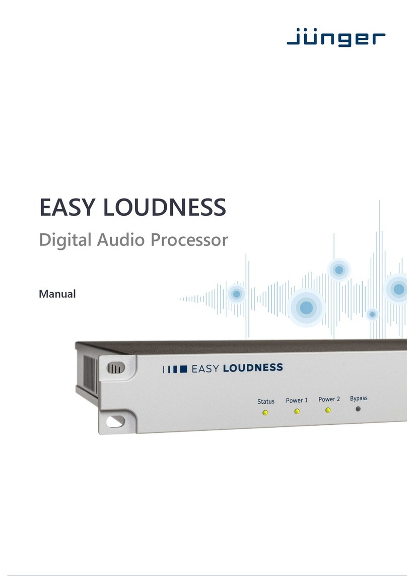
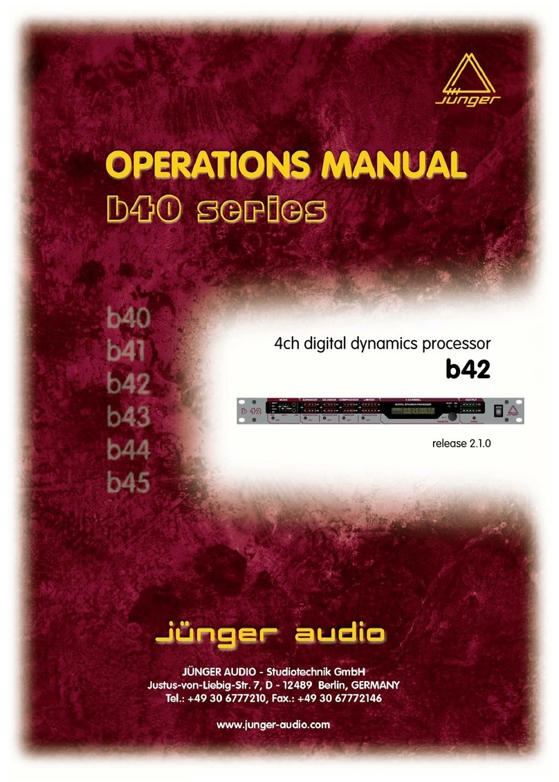
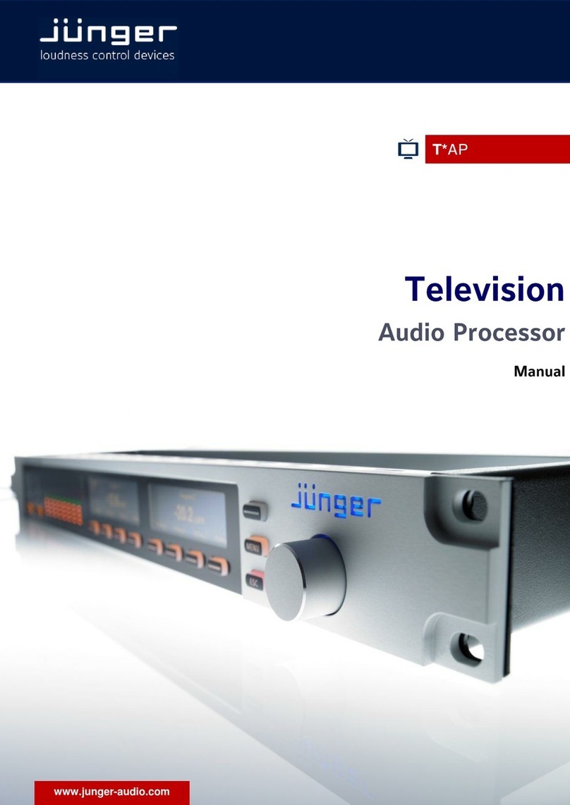
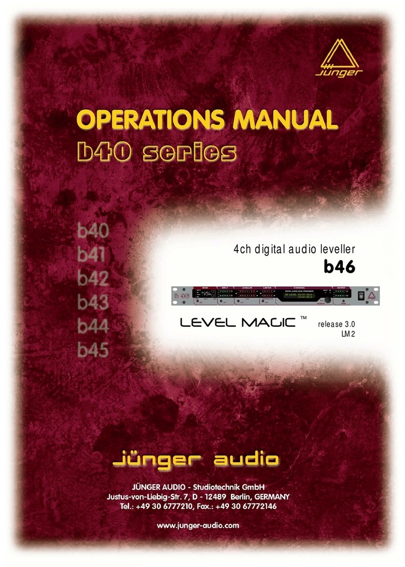
junger Accent1 User manual

digital dynamics processor
accent2
release 1.1


FOREWORD 0
Thank you for buying and for using the premium series digital dynamics processor
ACCENT2.
Not only you have aquired the latest generation of digital dynamic range processing,
but also a piece of equipment which is unique in its design and specification.
Please read this manual carefully to ensure you have all the information you need to
use the digital dynamics processor ACCENT2.
The unit was manufactured to the highest industrial standards and went through
extensive quality control checks before it was supplied.
If you have any comments or questions about installing, setting-up or using the
ACCENT2, please do not hesitate to contact us.
The information contained in this manual is subject to change without notice.
This manual is the copyright of Jünger Audio. All reproduction and copying, other than for legal owner’s
personal use, or disclosure of part or whole to a third party, is not allowed without prior written authorization
by Jünger Audio. © Jünger Audio, Berlin 1999-2004

CONTENTS 1
2. Function description ................................................................
2-1
2-1
2-2
2-3
2-3
2-3
2-4
2-4
2-5
2-6
2-6
2-7
2-7
2-7
2-7
2-8
2.1 Basic description ...............................................................
2.2 Block diagram ...................................................................
2.3 Audio signal processing ....................................................
2.3.1 Gain ...........................................................................
2.3.2 Compressor ................................................................
2.3.3 Expander ....................................................................
2.3.4 Limiter ........................................................................
2.3.5 Filter ...........................................................................
2.3.6 Dynamic filter .............................................................
2.3.7 Dither .........................................................................
2.4 Configurable audio path ...................................................
2.5 Insert routing ....................................................................
2.6 96kHz interfacing .............................................................
2.7 Analog inputs and outputs ................................................
2.8 Remote fader ...................................................................
3. Installation ...............................................................................
3-1
3-1
3-1
3-1
3-1
3-1
3-2
3-3
3-3
3-3
3-4
3.1 Unpack the unit ................................................................
3.2 Power supply .....................................................................
3.3 Connections ......................................................................
3.4 Rack mounting ..................................................................
3.5 Operation safety ...............................................................
3.6 Synchronization of digital output .......................................
3.7 Audio connections .............................................................
3.8 Remote Control ................................................................
3.8.1. GPI in / Tally Out ...................................................
3.8.2. Serial Remote Control ............................................
4-1
4-1
4-2
4. Location of parts and controls ................................................
4.1 Front panel ........................................................................
4.2 Rear panel .........................................................................

5-1
5-1
5-1
5-2
5-2
5-2
5-3
5-3
5-3
5-4
5-4
5-6
5. Operation ................................................................................
5.0 Description of operation .....................................................
5.1 Adjustment of parameters .................................................
5.2 Level display ......................................................................
5.3 Gain menu ........................................................................
5.4 Config menu ......................................................................
5.5 Compressor menu .............................................................
5.6 Limiter menu ......................................................................
5.7 Expander menu .................................................................
5.8 Filter menu .........................................................................
5.9 Setup menu .......................................................................
5.10 Recall and storage of presets ...........................................
6-1
6-1
6-2
6-2
6-3
7-1
7-1
7-1
7-1
8-1
8-1
8-1
8-1
8-2
9-1
6. Application notes .....................................................................
6.1 The Jünger Audio dynamics processor priniciple ..............
6.2 Influence of signal delay time ............................................
6.3 Changing the processing characteristic .............................
6.4 Selection of parameters to increase loudness ...................
7. Boot display and trouble shooting ............................................
7.1 Boot display .......................................................................
7.2 Error messages and trouble shooting ................................
7.3 Initialization the unit ............................................................
8. Technical specifications ...........................................................
8.1 Digital signal processing ....................................................
8.2 Digital inputs and outputs ..................................................
8.3 Analog inputs and outputs .................................................
8.4 General ..............................................................................
9. Warranty and service information ...........................................


2. FUNCTION DESCRIPTION
FUNCTION DESCRIPTION 2
BASIC DESCRIPTION 2.1
The digital dynamics processors by Jünger
Audio are high quality devices for adjusting the
dynamic range of digital audio signals in
mastering or studio applications.
All units are easy to use. The operation requires
only a limited number of manual settings to be
made by the user to achieve optimum results.
All other parameters required for inaudible
processing of the dynamic range are
automatically controlled by the program signal
and are constantly optimized.
The dynamic range processor principles
developed by Jünger Audio enable
compressors, limiters and expanders to be
produced with exceptionally high audio quality,
without coloration, pumping, breathing,
distortion or modulation effects sometimes
associated with this type of processor. In short,
almost inaudible pro-cessing - with ease of
use. All Jünger Audio dynamics processors
work according to a multi-loop principle,
operating in conjunction with multiple frequency
linear control circuits. The resulting attack and
release times of the system are variable and
are adapted to the characteristics of the input
signal. This allows relatively long attack times
during steady-state signal conditions but also
very short attack times when impulsive input
transients are present.
The premium series ACCENT digital dynamics
processors are dynamic range processors
which, contrary to their conventional
counterparts, are effective for a wide dynamic
range of input signals (50dB). The
compression of the program signal takes place
evenly over the entire dynamic range, not only
at the top end above a certain threshold level.
The dynamic structure of the input signal (e.g.
dynamic musical changes) are converted
proportionally so that even after compression
the ratios are maintained, only slightly
condensed, providing a transparent, seemingly
uncompressed result.
features
• 2-channel digital dynamic range processor
• accepts input sample rate from 44.1 up to
96kHz
• analog input and output with sophisticated
A/D- converter and D/A-converter working up
to 96kHz and 24bit
• high speed or 2-wire 96kHz interfaces
• configurable audio chain
• insert for digital or analog audio signals
• static or dynamic filter for signal path or in side
chain
stat/dyn, peak/shelv;
FRQ 20Hz...20kHz; Q 0.5...8.0; RNG -15...15dB
• adjustable gain (channel independent) -
15...+15dB
• 2-channel independent or stereo link mode
• adaptive controlled dynamic range processing
expander
on/off, THRS -70...-20dBFS, RANGE -20...0dB,
REL 0,2...4s
compressor
on/off, RATIO 1,0:1...4,0:1, RANGE 0...15dB,
Process 0...9
distortionfree look ahead limiter
on/off, THRS 0...-20dBFS, Process 0...9
• output dither 16 or 20bit
• sample rate conversion 96kHz...44.1kHz
• multiview level display
• optional output remote fader
• user friendly preset and recall function (99
presets)
• RS-232 interface for serial remote control
• GPI interface and tally output for parallel remote
control
operation manual accent2, chapter 2 -Function description- page 2-1
2. FUNCTION DESCRIPTION
2.2 BLOCK DIAGRAM
page 2-2 operation manual accent2, chapter 2 -Function description-

2. FUNCTION DESCRIPTION
AUDIO SIGNAL PROCESSING 2.3
All signal processing is done in the digital
domain by floating point signal processors.
The use of 32 bit word length for calculation
ensures that there is no deterioration in signal
quality, even if an audio signal with a maximum
word length of 24 bit is input into the
processing of the unit.
It is possible to choose different programs
for the Limiter and for the compressor. Each
program provides ideal dynamics control for
a different kind of programme signal
Selecting a particular program PRO 0...9 sets
up the optimum parameters of the dynamics
processor (attack and release times,
threshold levels and interactions between the
multiple signal dependent control circuits) for a
particular kind of programme material.
(In order to understand the basic Multi-loop
principle of the Jünger Audio dynamics
processors please refer to chapter 6.1, for
more information regarding control programs
read 6.3).
GAIN 2.3.1
GAIN means linear amplification of input
signals. The gain can be changed in steps of
0.1 dB , within a range from -15...+15 dB. Gain
amplification is done between compressor and
limiter processing.
The GAIN menu is opened by pressing the
GAIN button.
COMPRESSOR 2.3.2
The compression of the programme signal
takes place evenly over the entire input level
range and not only at the upper end above a
certain threshold level. Dynamic structures of
the input signal (e.g. dynamic evolutions) are
converted proportionally so that even after
compression the ratios are maintained, only
slightly condensed, leaving on the whole a
transparent, seemingly uncompressed sound
impression.
Compression (reduction of the dynamic range
of the input signal to match the dynamic
range of the storage or of the transmission
system) is partly achieved by increasing the
level of low level signals.
The lower the input signal level the higher
the additional gain applied to that input signal
by the compression processing will be.
Independent of the compression ratio , the
gain of the compressor (range) can be
limited (maximum 1 dB to 15dB), so that
there should be no inadmissible increase of
background noises during signal pauses (e.g.
live atmos, air-conditioning, hum and noise).
2.0:1
1.6:1
1.3:1
OFF
ratio
-50
-40
-30
-20
-10
[dBFS]-10-20-30-40-50-60
output
input
range
max. 15dB
fig. 2-1:
static characteristics:
compressor
operation manual accent2, chapter 2 -Function description- page 2-3

2. FUNCTION DESCRIPTION
2.3.3 EXPANDER
Below an adjustable threshold level an expander can be activated which can lower the amout of noise
signals. Range parameter describes the maximum attenuation within 6dB input level change below
threshold level.
gate
OFF
6dB
-50
-40
-30
-20
-10
[dBFS]-10-20-30-40-50-60
output
input
range
0...40 dB
threshold
level
-20...-60, off
fig. 2-2:
static characteristics:
expander
2.3.4 LIMITER
The static characteristics of the ACCENT2
usually refers to a digital output level of 0 dBFS
(dB Full Scale). This is useful for most
applications of the dynamics processor as the
on-following digital recording system is
supposed to be balanced down to the final bit.
For applications using headroom the output
level of can be adjusted within 0 ... -20 dBFS
in steps of 0.1 dB. The limiter threshold
determines the maximum output level but the
limiter threshold also determines the digital
reference level for the compressor. The static
characteristics of the compressor are related to
the limiter threshold.
The static characteristics fo limiter (solid) and
compressor (dotted) at a limiter threshold of -
12 dBFS are illustrated in fig. 7.
For the dynamics functions asignal delay of
approx. 2 ms is built in. This delay makes it
possible to arrange the algorithm of the limiter
in such a way that the control mechanism is
activated before maximum level is reached
(look ahead limiter). Within the rise time of the
signal the peak level is recognised and the
maximum is calculated in such a way that full
scale level is reached precisely without
causing clipping.
audio processing of
compressor is related
to limiter threshold level
-50
-40
-30
-20
-10
[dBFS]-10-20-30-40-50-60
output
input
limiter
threshold
0...-20dBFS
max. output
level
fig. 2-3:
basic function:
limiter
page 2-4 operation manual accent2, chapter 2 -Function description-

2. FUNCTION DESCRIPTION
FILTER 2.3.5
The digital dynamics processor offers a filter
for the creation of the desired sound setting or
for creating dynamic range processing (f.i. de-
esser). The filter can be used in audio signal
path or in side chain. The location of the filter is
to set in CONFIG menu.
The filter can be shelving or peaking type.
Depending on the selected characteristic the
parameter centre frequency , range (filter gain)
and Q are adjustable.
The Q control affects how frequency selective
the gain control is when boosting or
attenuating. On a high Q the gain control has
influence for a small range of frequencies. With
low Q the gain control will boost or cut a whole
range of frequencies.
fig. 2-4:
peaking filter
gain
(boost or cut)
-15..+15dB
frequency
-25
-20
-15
-10
-5
[dBFS]
20k10k1k500100
Input
level
Q
0.5...8.0
center
fre
q
uenc
y
fig. 2-5:
shelving filter
gain
-15..+15dB
frequency
-25
-20
-15
-10
-5
[dBFS]
20k10k1k500100
Input
level
center
frequency
high
shelving
operation manual accent2, chapter 2 -Function description- page 2-5

2. FUNCTION DESCRIPTION
2.3.6 DYNAMIC FILTER
In dynamic mode the filter activity is controlled
by the audio level. The filter get active only if
the level of incoming audio signal reaches a
defined threshold level. A typical application for
a dynamic filter is the de-esser function.
There are two basic modes for the dynamic
equaliser, dependent on adjusted RANGE
value.
Negative values for RANGE (cut function)
switches into REDUCE mode. In REDUCE
mode signals will be reduced if their level is
higher as the threshold level.
All spectral parts of the signal (selected by the
filter band) which has more level as the
adjusted threshold level will be reduced by the
RANGE value. The level reduction never
comes below the threshold level.
Positive values for RANGE (boost function)
switches into ENHANCE mode. In ENHANCE
mode signals will be increased (or enhanced) if
their level is below the threshold level.
All spectral parts of the signal (selected by the
filter band) which have less level as the
adjusted threshold level will be increased by
the RANGE value. The increased level never
comes over the threshold level.
threshold
REDUCE MODE
RANGE value negative (cut)
frequencylevel
ENHANCE MODE
RANGE value positive (boost)
threshold
frequencylevel
2.3.7 DITHER
The digital output signal has a word length of
24 bit. The information of a 24 bits signal is not
more storable linear in most cases. One must
shorten 24 bits data word to 20 or 16 bit word
length.
In order to receive a better sound quality
during cut down the data to 20 or 16 bit, one
must redither the material. This is done by
calculating random numbers (dither signal) and
add a random number to every sample. Then it
will be cut off to 16 bit. As a result, the bit with
least weight (LSB) is put in such a way that it
corresponds best to the information of the last
bits following available ones no more and
makes less distortions as hissing in the signal.
Dither is switched off for digital zero signals
(auto-blacking).
page 2-6 operation manual accent2, chapter 2 -Function description-

2. FUNCTION DESCRIPTION
The audio chain of the processing is
configurable through the user to extend the
possible applications of the device.
Changing the audio chain means to move the
filter block in one of four possible positions.
The selection is to do by calling the CONFIG
menu.
CONFIGURABLE AUDIO PATH 2.4
FLT-EXP-COMP-GAIN-LIM
EXP-FLT-COMP-GAIN-LIM
EXP-COMP-GAIN-LIM
FLT
EXP COMP-GAIN-LIM
FLT
INSERT ROUTING 2.5
It is possible to have an insert for the audio
signal to slave external devices into the signal
path of the unit.
Insert send and return are fixed before the
compressor block.
Insert is not available if 2-wire interfacing is
used. Insert is displayed in CONFIG menu.
INS
FLT-EXP COMP-GAIN-LIM
INS
EXP-FLT- COMP-GAIN-LIM
INS
EXP- COMP-GAIN-LIM
FLT
INS
EXP COMP-GAIN-LIM
FLT
96 KHZ INTERFACING 2.6
ACCENT processor supports two methods of
transport of digital audio signals with more than
48 kHz sampling rate. Both interface modes -
2-wire at normal sample rate or high speed
interface- are available. Interface assignment
is to set in setup menu. 2-wire interface and
digital insert can’t be used at the same time.
2-wire = 2 AES/EBU-lines, one for each
channel, clocked with the half of the original
sample rate
high speed = 1 AES/EBU-line with two
channels of audio, clocked with original sample
rate
ACCENT2 processor is equipped with analog
inputs and outputs.
These are made by using sophisticated state-
of-the-art A/D-converters and D/A-converters
developed by Jünger Audio. The converters
can run with sample rates up to 96kHz
supporting true 24bit wordlength.
ANALOG INPUTS AND OUTPUTS 2.7
The exeptional high quality of the converter
modules and their reliability guarantees most
accurate conversion for a long term of use of
the unit. ACCENT processor is useful as
standard high-quality A/D-converter for
conversion and processing of audio material
for all existing and future available digital audio
distribution formats.
operation manual accent2, chapter 2 -Function description- page 2-7

2. FUNCTION DESCRIPTION
If a fade is performed before the ACCENT, the
compressor will try to increase the level as the
fader decreases. Therefore the fade must be
done after the compressor. ACCENT is
supporting the performance of hand-fades by
using a remote fader. These fades are
calculated in digital domain. If the maximum
range for the fader is selected the minmum
fader position is digital zero. Activating and
calibration of the fader is to do in the SETUP
menu (see chapter 5).
We recommend to use the MasterFader of
t.c. electronic a/s.
REMOTE FADER 2.8
potentiometer
50kOhm, linear
operation manual accent2, chapter 2 -Function description- page 2-7

3. INSTALLATION
INSTALLATION 3
UNPACK THE UNIT 3.1
The digital dynamics processor ACCENT2 was
carefully packed in the factory and the
packaging was designed to protect the
equipment from rough handling.
Please examine carefully the packaging and its
contents for any signs of physical damage,
which may have occured in transit.
POWER SUPPLY 3.2
The digital dynamics processor ACCENT2 is a
device under the safety category
Schutzklasse1 in keeping with the VDE 0804
standards and may only used with power
supply installations built according to
regulations.
Check the voltage details printed at the rear
panel are the same as your local mains
electricity supply.
CONNECTIONS 3.3
The digital dynamics processor ACCENT2 is
equipped with standard connectors (see also
chapter 4).
Before connecting the digital dynamics
processor ACCENT2 switch the power off at all
connected units.
RACK MOUNTING 3.4
The digital dynamics processor ACCENT2 is
made as standard 19“ unit (EIA format). It
occupies 1 RU (44 mm height) space in a rack.
Please allow at least addititonal 3“ depth for
the connectors on the rear panel.
When installing the unit in a 19“ rack the rear
side of the unit needs some support, especially
for mounting in flight cases.
OPERATIONSAFETY 3.5
The digital dynamics processor ACCENT2
should not be installed near units which
produce strong magnetic fields or extreme
heat. Do not install the filter processor directly
above or below power amplifiers.
If, during operation, the sound is interrupted or
displays no longer illuminate, or if abnormal odor
or smoke is detected immediately disconnect
the power cord plug and contact your dealer or
Jünger Audio.
operation manual accent2 chapter 3 -Installation- page 3-1

3. INSTALLATION
3.6 SYNCHRONIZATION OF DIGITAL OUTPUT
The digital dynamcis processor ACCENT2 has
two digital signal outputs. The main digital
output (XLR1, BNC1) can be combined with a
sample rate converter. Working with SRC it
can have sample rate at the output different
from the system clock. If the SRC is switched
off it is following the system clock. The second
digital output (XLR2, BNC2) is following the
system clock allways. The system clock is
following either the sample rate of the selected
digital input or the sample rate of the A/D-
converter.
The sample rate for the A/D-converter can be
set in setup menu. It is possible to use internaI
reference frequencies or external sync.
The requested sample rate for the main digital
output with SRC can be set in setup menu. It
is possible to use internaI reference
frequencies or external sync. In case of using
internal sync for the ADC the SRC can be
synchronized by external sync only. If external
sync is selected the main digital output locks to
the wordclock signal connected to EXT SYNC
input. To the problem-free combination of
following digital devices, the wordclock
reference used for the output with sample rate
converter is available at W-CLOCK output.
SRC
A
DC int Ref
digital input
analog input
ACCENT2
dsp dig out2
dig out1
ext Ref
SRC
A
DC int Ref
digital input
analog input
ACCENT2
dsp dig out2
dig out1
ext Ref
SRC
A
DC ext Ref
digital input
analog input
ACCENT2
dsp dig out2
dig out1
int Ref
SRC
A
DC ext Ref
digital input
analog input
ACCENT2
dsp dig out2
dig out1
SRC
A
DC int Ref
digital input
analog input
ACCENT2
dsp dig out2
dig out1
ext Ref
input: analog, int Ref
clock rates
system/dsp: int Ref
dig out1: SRC, ext Ref
dig out2: int Ref
input: analog, ext Ref
clock rates
system/dsp: ext Ref
dig out1: SRC, int Ref
dig out2: ext Ref
input: analog, ext Ref
clock rates
system/dsp: ext Ref
dig out1: SRC, ext Ref
SRC could be switched off!
dig out2: ext Ref
input: digital
clock rates
system/dsp: input digital
dig out1: SRC, ext Ref
dig out2: input digital
input: digital
clock rates
system/dsp: input digital
dig out1: SRC, int Ref
dig out2: input digital
page 3-2 operation manual accent2 chapter 3 -Installation-

3. INSTALLATION
The ACCENT2 audio inputs are RFI filtered and
with the outputs electronically balanced and
floating. All the audio connectors are via rear
panel mounted connectors. Standard XLR
connectors are used. These are allways wired
to the AES standard:
pin 1 X Screen screen
pin 2 L Live audio 0°
pin 3 R Return audio 180°.
AUDIO CONNECTIONS 3.7
Balanced connections are to be preferred
whenever the other equipment provides
balanced inputs/outputs. All line level
connections should be wired with twin screened
cable for low noise and reliability. The screens
of the cable should be connected at one end
only. Input cable screening therefore needs to
be derived from the signal source end as pin 1
is ground lifted at low frequencies for the inputs.
If the equipment driving the ACCENT2 has
unbalanced outputs then you will need to add a
wire jumper such that the screen connection of
Pin 1 of the XLR is shorted to Pin 3.
If the equipment being connected to the mpx01
have only unbalanced inputs, then we
recommend still to use a balanced (ie. 2 core
shielded cable) cable where Pin 1 and Pin 3 are
connected in the cable ends away from the
ACCENT2.
REMOTE CONTROL 3.8
GPI IN / TALLY OUT 3.8.1
The Digital Dynamics Processor ACCENT2
can be remote-controlled by means of parallel
GPI contacts. Even it can signal specific
device statuses via parallel Tally lines.
use : remote-controlled changeover of
presets or other events
connector: D-SUB 9pin, female
Pin assignments
5 1
9 6
Pin Signal name Logic I/O Functions
1 GPI1 L I as assigned (see chap.5)
2 GPI2 L I as assigned (see chap.5)
3 GPI3 L I as assigned (see chap.5)
4 GPI4 L I as assigned (see chap.5)
5 GROUND Ground
6 TALLY1 H O as assigned (see chap.5)
7 TALLY2 H O as assigned (see chap.5)
8 TALLY3 H O as assigned (see chap.5)
9 TALLY4 H O as assigned (see chap.5)
Electrical specification:
GPI input On: connection to ground
Off: open
min. 50 ms
+1,5V
+3,5V
signal input level L: 1,5V or less, min. 50ms
level H: 3,5V or more
operation manual accent2 chapter 3 -Installation- page 3-3

3. INSTALLATION
Tally output level L: 1,5V or less
level H: 3,5V or more
TALLY OUT
max. 25 mA
+5 V
110 Ohm
3.8.2 SERIAL REMOTE CONTROL (RS-232)
The Digital Dynamics Processor ACCENT2
can be remote-controlled by means of serial
remote RS-232.
use : remote-controlled
changeover
of parameter
protocol: available on request
connector: D-SUB 9pin,
input - male
output - female
Pin assignments
The cable is wired 1:1 completely, the shield of the cable must be connected on both ends!
5 1
9 6
REMOTE IN
Pin Signal name Functions
1 not used
2 TXD in Transmit data
3 RXD out Receive data
4 not used
5 GND ground
6 DSR Data set ready, is high
7 not used
8 not used
9 not used
Electrical specification:
signal in-/outputs TTL-level
page 3-4 operation manual accent2 chapter 3 -Installation-

4. LOCATION OF PARTS AND CONTROLS
LOCATION OF PARTS AND
CONTROLS 4
FRONTPANEL 4.1
fig1: front panel accent2
SELECT /EDIT knob
RESET mains
switch
multiview display
BYPAS
FILTER
GAIN
CONFIG COMPRESSOR
EXPANDER
EDIT
display
SETUP
PRESET
LIMITER
GAIN selection/adjustment of gain and balance CONTROL
ELEMENTS
CONFIG selection of audio path configuration
COMPRESSOR selection of compressor menu
green LED in button lits if compressor is on
EXPANDER selection of expander menu
green LED in button lits if expander is on
LIMITER selection of limiter menu
green LED in button lits if limiter is on
FILTER selection of filter menu
green LED in button lits if filter is on
SELECT/EDIT selection and adjustment (push or turn)
of processing and setup parameters
PRESET selection of preset menu
SETUP selection of setup and utility menus
RESET reset for peak hold and overload indicators
BYPASS switch for general bypass of the unit
Operation manual ACCENT2, chapter 4 -location of parts and controls - page 4-1

4. LOCATION OF PARTS AND CONTROLS
4.2 REAR PANEL
accent2
ANALOG INPUT
LEFT RIGHTLEVEL RIGHTLEVEL
ANALOG OUTPUT
LEFT
DIGITAL OUTPUT
BNC2
BNC1
XLR1 XLR2
DIGITAL INPUT
BNC2
BNC1
XLR1 XLR2
230 V
50 Hz
200 mA GPI
REMOTE SYNC IN
WCLK OUT
FADER
DIGITAL INPUTS
ANALOG
OUTPUTS
SYNC
IN/OUT ANALOG
INPUTS
DIGITAL OUTPUTS
SERIAL
REMOTE
FADER
GPI
REMOTE/
TALLY
fig. 2: rear panel ACCENT2
POWER INPUT
IEC mains input connector 100-240V, 50/60 Hz with integrated fuse
REMOTE
serial remote interface RS-232
connector: 9pin SUB-D, female
GPI
parallel remote interface GPI in/TALLY out
connector: 9pin SUB-D, female, TTL-level
SYNC
EXT SYNC
input for external sync signal
wordclock, TTL level, 1 kOhm, unbal.
connector: BNC socket,
W-CLOCK
output for sync signal
wordclock, TTL level, unbal.
connector: BNC socket
FADER
input for remote fader
connector: 6.3 mm phone plug
DIGITAL IN
input for AES/EBU standard format
connector: XLR female panel jack, 1- ground, 2-3 signal, balanced
connector: BNC socket 75 Ohm, unbalanced
DIGITAL OUT
output for AES/EBU standard format
connector: XLR male panel jack, 1- ground, 2-3 signal, balanced , 4 Vpp
connector: BNC socket 75 Ohm, unbalanced, 0.5V pp
ANALOG IN
input for analog audio signals
connector: XLR female panel jack, 1- ground, 2- hot, 3- cold, 10kOhm, floating balanced
ANALOG OUT
output for analog audio signals
connector: XLR male panel jack, 1- ground, 2- hot, 3- cold, 50Ohm, floating balanced
page 4-2 Operation manual ACCENT2, chapter 4 -location of parts and controls -
This manual suits for next models
1
Table of contents
Other junger Computer Hardware manuals

junger
junger b42 User manual

junger
junger D-AP LM4 User manual

junger
junger d07 User manual

junger
junger EASY LOUDNESS User manual

junger
junger D*AP4 FLX User manual

junger
junger b40 User manual

junger
junger T-AP User manual

junger
junger V*AP User manual

junger
junger d07 User manual

junger
junger T-AP User manual
Popular Computer Hardware manuals by other brands

WEG
WEG EXP- SE-I1R1F2-ADV instruction manual

Siemens
Siemens CP 5613 A3 operating instructions

Cypress
Cypress MB9B160R Series Operation manual

Motorola
Motorola M68MPB16Y1 user manual

Microchip Technology
Microchip Technology AVR128DB48 Curiosity Nano Hardware user's guide

ZALMAN
ZALMAN ZM-WB3 Gold user manual