junger D-AP LM4 User manual

www. .com
jungeraudio
D*AP


Rev. 130705
D*AP LM 4
Hardware
•
1RU compact 19" processing device with front panel
•
Front Panel displays 4ch LED bar graph, operating display, LED status display
•Front Panel buttons BYPASS, METER, 4x function control, SEL, MENU, ESC
•Rotary encoder predefined functions, context sensitive modes
•
4 channel audio DSP 2 Analog Devices® Sharc floating point processors
•
2
x AES3 and 2x AES3id on board with independent relay bypass and auto input selection
•
2
x SRC selectable per AES input
•
External sync IN 75 Ωinput (Word Clock, AES3id, Black Burst, Tri-Level)
•
Sync OUT 75 ΩWord Clock output
•RJ45 network connector 100BaseT full duplex Ethernet interface
•USB "B" connector built in USB < > serial adapter to access the device service port
•8 GPIs balanced inputs on 25pin Sub-D
•
8 GPOs relay change over contacts on 25pin Sub-D
•
Aux power supply build in isolated 5 V supply for external GPI/O wiring
• Optional dual power supply load balanced, auto fail over
•One interface slot I/O expansion slot for option modules :
3G / HD / SD SDI module option module 3G SDI de-embedder / embedder with relay bypass
8Ch AES I/O module option module 4x AES3id I/Os with relay bypass
4Ch analog I/O module option module 4x analog line I/Os with relay bypass
8Ch analog out module option module 8x analog line out with relay protection
operating manual

1
D*AP LM 4
Content
page
block diagram ………………………………………………………………………………………. 2
audio processing blocks ……………..……………………………………………………………. 2
getting started .....………………….………………………………………………………………. 3
getting started – IP setup of the device via front panel ………………………………………… 3
getting started – IP setup of the device – via console interface ...……………………………. 4
getting started – IP setup of the device – via web browser ..….………………………………. 5
Operating …………………………………………………………………………………………… 6
Operating – menu structure of the front panel ………………………………………………….. 6
Operating – front panel navigation tree …………………………………………………………. 7
Web GUI ……………………………………………………………………………………………. 8
Web GUI – SYSTEM – Overview ……………………………………………………………….. 9
Web GUI – SYSTEM – Admin …………………………………………………………………….. 10
Web GUI – SYSTEM – Setup …………………………………………………………………….. 12
Web GUI – SYSTEM – The preset concept in detail ………………………………………….. 12
Web GUI – SYSTEM – SNMP ……………………………………………………………………. 13
Web GUI – SYSTEM – Backup / Restore ……………………………………………………….. 13
Web GUI – SYSTEM – Software Update ……………………………………………………….. 14
Web GUI – SYSTEM – Reboot …………………………………………………………………… 14
Web GUI – SYSTEM – System Status …………………………………………………………… 15
Web GUI – INTERFACES – AES I/O ……………………………………………………………. 16
Web GUI – INTERFACES – SDI I/O Interface – De-Embedder ……………………………… 17
Web GUI – INTERFACES – SDI I/O Interface – Embedder …………………………………. 18
Web GUI – INTERFACES – SDI I/O Interface – Setup ……………………………………….. 20
Web GUI – INTERFACES – (SDI I/O Interface) Status………………………………………… 21
Web GUI – ROUTING …………………………………………………………………………….. 22
Web GUI – AUDIO PROCESSOR – Overview …………………………………………………. 23
Web GUI – AUDIO PROCESSOR – Setup ……………………………………………………. 23
Web GUI – AUDIO PROCESSOR – Input …………………………………............................. 24
Web GUI – AUDIO PROCESSOR – Fail Over ……………………………………………….... 25
Web GUI – AUDIO PROCESSOR – Filter – Spectral Signature ……………………………… 26
Web GUI – AUDIO PROCESSOR – Filter – Equalizer ………………………………………… 27
Web GUI – AUDIO PROCESSOR – Dynamics ………………………………………………… 29
Web GUI – AUDIO PROCESSOR – Voice Over ……………………………………………… 30
Web GUI – AUDIO PROCESSOR – LevelMagic™ …………………………………………….. 32
Web GUI – AUDIO PROCESSOR – Output …………………………………………………..... 34
Web GUI – EVENTS – Trigger – Trigger Configuration ………………………………………. 34
Web GUI – EVENTS – Trigger – Remote Hotkey Sources …………………………………… 35
Web GUI – EVENTS – Trigger – Network Sources ……………………………………………. 36
Web GUI – EVENTS – Trigger – Parameter Sources …………………………………………. 37
Web GUI – EVENTS – Events – Preset Events – System …………………………………….. 37
Web GUI – EVENTS – Events – Preset Events – Interface …………………………………… 38
Web GUI – EVENTS – Events – Preset Events – Routing ……………………………………. 38
Web GUI – EVENTS – Events – Preset Events – Audio Processor ………………………….. 39
Web GUI – EVENTS – Events – Action Events – GPO………………………………………… 39
Web GUI – EVENTS – Events – Action Events – Loudness Measurement ………………… 40
Web GUI – EVENTS – Events – Bypass Events ………………………………………………. 41
Web GUI – EVENTS – Events – Example Setup ………………………………………………. 42
Technical data …………………………………………………………………………………...... 44
Technical data – base unit rear connectors – pin assignment ……………………................. 45
Technical data – interface modules – SDI De-Embedder / Embedder [SDI 150] ………… 46
Technical data – interface modules – 4x AES I/O [DD 188] ………………………………… 47
Technical data – interface modules – 4x analog I/O [AN 144] ………………………………. 47
Technical data – interface modules – 8x analog I/O [AN 104] ………………………………. 47
Technical data – optional interface modules – pin assignment ………………………………. 48
safety information …..……………………………………………………………………………… 49
warranty …………………………………………………………………………………………….. 49
2
D*AP LM 4
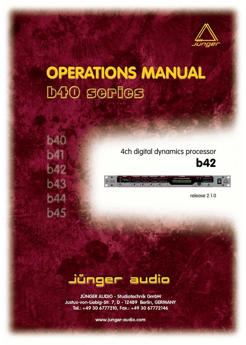
Block diagram :
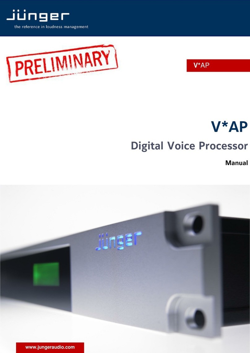
Audio processing blocks :

3
D*AP LM 4
Getting started
Communication with the LM 4 is via TCP/IP over Ethernet and each unit is shipped with a default IP address.
Before the unit can be controlled, the following steps are required:
1. Obtain a unique IP address for the network onto which it will be installed.
2. Overwrite the default IP address with the new one by one of the methods below.
3. Ensure that the computer has an upto date version of Java installed and that any firewall is configured to
allow UDP data to be returned to the unit
For specific advice, please consult your network administrator
Getting started – IP setup of the device via front panel
After power up the front panel shows the idle display:
SHORT-TERM 3s
CH 1/2
IN
-70.0
OUT
-70.0
Now you must press <MENU>. This will show HOTKEYS menu entrance. Now turn the Rotary Encoder
[RE] one turn left and you reach the CONFIG menu. Press the <RE> and the menu item NETWORK will be
displayed. Press <RE> again and you will enter the network setup :
IP
10. 110. 3. 73.
If you turn the RE to the right, you may select between IP, MASK and GATEWAY. If you press the
<
RE> now
you will enter the setup display of the respective item.
Flashing arrow markers (cursors) will appear in one of the fields, to indicate that you may change this value
by turning the RE. Below an example for the IP address:
IP
>10<
110. 3. 73.
Pressing <SEL> will move the flashing cursors to the next address field(s). After performing the setup you
must press <MENU>.to apply the changes:
IP CONFIG CHANGED
OK : APPLY ESC : DISCARD
Pressing <RE> will store the changes and will reboot the device in order to apply and use it.
APPLYING CHANGES
REBOOTING . . .

4
D*AP LM 4
Getting started – IP setup of the device via console interface
The tool to change the IP configuration of the device will be reached via the console interface. You must
connect the LM 4 with the PC via an USB A to B cable. Before connecting the cable you must have the
FTDI driver installed on your PC. You will get it from the Co web site:
http://www.ftdichip.com/FTDrivers.htm
You must go for the VCP (Virtual Com Port) Drivers section and select the "setup executable" that matches
your PC processor. E.g. "CDM20814_Setup.exe". Download the file and run it.
This will install the driver for the built in USB to serial converter. Now you can connect the cable and open a
terminal program. Here you must select the virtual COM port assigned by the OS. The communication
parameters are:
115200kBaud, 8, N, 1 no hand shake. Pressing <ENTER> will open the console menu:
Go for item 2 and press <ENTER>:
"Your choice: 2"
"Current network configuration
IP Address : 10.110.24.128
Netmask ... : 255.255.0.0
Gateway ... : 10.110.0.1
You must enter the IP address and the netmask.
Enter new IP address, press ENTER to cancel: "192.168.176.78" <Enter>
Enter new netmask, press ENTER to cancel: "255.255.255.0" <Enter>
Important Note! The gateway entry is optional but you must take care that the gateway address is matching
the network mask related to the device IP address!
If you’re not sure simply enter 0.0.0.0.
Enter new gateway, press ENTER to configure without gateway: "0.0.0.0" <Enter>
Network configuration has been changed. Please reboot the device
To activate the new settings.
Select item 8 and press <ENTER>:
Do you want to reboot the device?
Press small "y“:
Do you want to reboot the device? y
Press <ENTER>
Rebooting the device ……..
After reboot has finished the new IP configuration is active.

5
D*AP LM 4
Getting started – IP setup of the device via web browser
* Read the default IP address printed on a label between mains sockets.
* Set up network parameters of the PC which meet the default IP address of the LM 4
(net mask = 255.255.0.0).
* Connect the device with the PC either by an Ethernet cross over cable or by a switch.
* Open a browser and type the device IP address into the URL field and press <ENTER>.
This will open the AUDIO PROCESSOR >> Overview pane of the GUI.
* Click on SYSTEM and the "Admin" pane will open automatically:
Enter the desired network configuration into the marked area and press <apply>
Afterwards you must reboot the device in order to activate the new IP configuration.
Regarding Gateway address see above.
Important Note! After reboot the web browser may not be able to communicate with the LM4. You must key
in new IP address in the URL field.

6
D*AP LM 4
Operating
Operating – menu structure of the Front Panel :
The display after power up – the idle display – shows the input "IN" and output "OUT" short term (3secs.)
loudness of the programs processed by the respective device channels. E.g.:
SHORT-TERM 3s
CH 1/2
IN
-70.0
OUT
-70.0
If you turn the RE the display will change to the True Peak Hold display of the respective channels:
TRUEPEAK-HOLD
CH 1/2
IN
-70.0
OUT
-70.0
And vice versa. If you press <SEL> you will see the values of the other processing channels.
Pressing <ESC> will reset the display reading (HOLD reset).
The 4 direct function buttons of the front panel will move you to the respective function blocks
where the RE selects the respective items.
<MODE> LOUDNESS MODE > SYNC SOURCE
< MUTE < ENABLE < LINK
<INPUT> INPUT GAIN > MONO > HP FILTER > LP FILTER > DELAY >
INPUT ROUTING BIT TRANSPARENT
< LINK
<LEVELER> ENABLE > LOUDNESS TARGET > TIME > MAX GAIN >
FREEZ LEVEL > TP MAX GAIN > TP RESPONSE > PROCESSING >
CLEAR HISTORY > INITIAL GAIN > THRESHOLD
<LIMITER> ENABLE > MAX TRUE PEAK > PROCESSING
The overall parameter menu structure is shown on the next page.

7
D*AP LM 4
Operating
–
front panel navigation tree :

8
D*AP LM 4
Web GUI
Type the device IP address into the URL field of a browser to display the initial web page
of the D*AP-LM4 :
The default view is a general block diagram of the audio processing section.
Firstly you must set up basic things such as program configuration, give the programs meaningful names and
set the synchronization source. You may also give the device a name, tell it its location and define an
administrative contact which may be used by monitoring systems of your house (e.g. via SNMP).
Selecting any of the top 5 tabs (SYSTEM, INTERFACE, ROUTING, AUDIO PROCESSOR, EVENTS) will
reveal a second row of options specific to the chosen tab.
The following paragraphs will guide you through the set up of the LM 4 step by step.

9
D*AP LM 4
Web GUI –SYSTEM – Overview
The graphical overview shows the main building blocks of the device including the options installed such as a
SDI interface module.
You may click into the boxes and the respective page will open. The navigation is based on URLs so you may
use the <Back> navigation button of the browser to return to this page.

10
D*AP LM 4
Web GUI –SYSTEM – Admin
Admin – allows for the setting of global options including device name and time, network and remote service,
diagnostics and start up page view of the preset editor.
This D*AP input fields for information utilized by higher level services.
Name give the device a meaningful name that may be used by name services
and SNMP management.
Location the place where the LM 4 is located
Admin / Contact e-mail address of a person in charge.
Graphical User Interface defines the appearance of the parameter panes regarding preset editor
and on air parameter visibility (see below – for preset concept).
Device Time allows you to set the device clock. At the factory it is set to
UTC (Coordinated Universal Time).
Date if you click into the Date input field,
a comfortable calendar tool will pop up :
Time if you click into the Time input field,
you will be able to set the device time.

11
D*AP LM 4
Authentication to prevent non authorized people from changing device settings the
administrator may assign passwords for either the admin and/or an
operator (same applies for talent/artist). While the admin is allowed to set
everything, an operator is just allowed to load presets. Parameters will be
reset if there was an attempt from the operator to change it.
Enable [enable / disable]
the administrator may turn authentication off.
Change Password for [admin / operator]
Select which password you will set / change
Password key in a password
Default passwords are: admin (for admin) and operate (for operator).
Repeat repeat that password
Important Note! The authentication may be enabled / disabled form the console interface as well
(see page 8 "1: Manage Password") via USB connection but also via Telnet! If you have higher security
demands you should turn the Telnet server off. Authentication will turned off and passwords will be reset if
one initializes the device to factory default (see Reboot - page 19, INIT/RESET rear button - page 4).
If there was an authentication failure, the admin
will be notified on next proper login about such conditions :
The pop up appears as often as an login failed.
Network IP address setup, see above: "Getting started – IP setup of the device
via web browser"
IP Address
Netmask
Gateway
Transmit Metering Data metering data will be streamed via UDP protocol. In order to receive such
data by external applications you must define ports (port range) for
matching fire wall definitions.
Enable streaming of metering data via UDP on demand of an external application
(web browser, J*AM, 3
rd
party).
UDP Port Range Start lowest port number.
UDP Port Range End highest port number.
an external application, that can not be configured prior to start up like the
web GUI will ask the LM 4 for the possible port range and will start looking
if the first port is available on the PC where the application resides. If yes it
will tell the LM 4 to start streaming on that port.
If not the application must look for next available port.
Other applications like the J*AM which have pre definitions will not ask the
LM 4 for possible UDP port range. They will use the one from the
application set up menu.
Service Options
Maintenance Interface
via RPC for in house use to enable communication with factory tools.
Telnet Server enables a telnet server to connect the consol interface via IP (port 21).
Diagnostics
get diagnostics file pressing this soft button will start the assembly of a diagnostics file.
The file will be presented in XML format for download.
If you experience unexpected behavior of the device you may be asked by
the Junger service team to send such file by e-mail for analysis.

12
D*AP LM 4
Web GUI –SYSTEM – Setup
Setup – Allows the editing of program labels for the 2 stereo input sources along with the sync source
selection. Displayed to the right is the PRESETS window which is common to many of the set up screens.
Presets allow for up to 20 different parameter settings that can recalled when desired.
Program Labels each of the individual programs has a name that will be used as a
reference for the display of parameters and its setup.
D*AP Synchronization Source with this pull down you may select between the available sync
sources :
Internal 48kHz, External AES, Input AES 1/2, External WCL,
Interface (if an option board is installed),
Black Burst / TriLevel).
Web GUI –SYSTEM – The Preset concept
in detail
The example above shows the preset concept of the LM 4. It is the central theme of the device.
For all relevant setting of the device one set of ON AIR parameters and 20 sets of PRESETS are available If
you want to load parameters from a preset or save parameters from the ON AIR area
to a preset, you must first select a preset number at the bottom of the ON AIR page.
You must press to open the pull down list to select the desired preset.
Pressing will execute it. When you press , you will be asked in a pop up :
to overwrite the selected preset and to give it a (new) name.
acts as a clip board for the parameters of individual presets,
while will allow you to store / recall the set of 20 presets to / from the PC file system.
Important note! The presets of the LM 4 are persistent by nature. You are working directly on the preset
memory, i.e. you must not worry about storing such presets. The LM 4 does it for you.

13
D*AP LM 4
Web GUI –SYSTEM – SNMP
SNNP – Here you can set up the Simple Network Management Protocol options including alarms and
notification path. You may also select what kind of Trap the LM 4 must send in case of emergency.
Web GUI –SYSTEM – Backup / Restore
Backup / Restore – All device settings and parameters can be either backed up for future recall, or restored
from a previously created backup file.
If you press the device controller will collect all necessary data and assemble it to an XML file. Finally
you will get a pop up message:
You must select :
<Save File>.
After pressing <OK>, the
system file dialog opens :
Select a folder
and alter that default file name
if needed.

14
D*AP LM 4
Web GUI –SYSTEM – Software Update
Software Update - The files to update the LM 4 will be available in ZIP format. You must unpack it to your
PC in order to access them for the update procedure.
You will find an image file for the LM 4 core system in the format: "rel_lm4_x_y_z.img"
as well as update files for components, like the optional interface boards
in the format: "rsdi150_v47.sdi".
To update the LM 4, you must <Browse …> for the respective
Firmware File(which you have unzipped before) and press .
After finishing the procedure the device will reboot.
You may also update the firmware of an SDI board installed in one of the
two interface slots (or both). The example above shows one SDI I-O board installed into
interface 1 slot. You must select the appropriate file from the firmware update bundle (ZIP file)
and press afterwards.
The LM 4 has a few options you may buy extra. Which option is active on your device you can read from
the licensing display in the bottom right part of this page. If you buy a license later on you must save the
"license info" file and send it to your dealer. After purchasing the option you will get a "license" file in return
which you must apply from there. After rebooting the device the license becomes active.
Web GUI –SYSTEM – Reboot
Reboot – Following changes to the set up or configuration, a reboot may be required. Two additional
options allow for restoring the factory default settings and overwriting the current network IP settings if they
have been changed.

15
D*AP LM 4
Web GUI –SYSTEM – System Status
System Status – Provides a current overview of critical system parameters including device, processing and
interface status along with a system log and any system messages.
Device Status provides the hardware status of the LM 4
Power 1 status of the first power supply (left hand side from rear)
Power 2 (optional) status of second power supply (right hand side from rear)
Temperature measured on the surface of the main PCB
Sync Lock turns red if the external sync source is removed or unstable
Processing Status
Bypass turns red if Bypass is activated
Interface Status
AES I/O turns red if an AES input that is internally in use (i.e you have routed it to
an input of a function block) has detected an error
SDI I/O Interface turns red if the SDI input is not locked (no or bad SDI signal)

16
D*AP LM 4
Web GUI –INTERFACE – AES I/O
AES I/O – Allows the set up of AES input source selection along with a display of signal input status.
Input Status each AES input has a status detection that may show :
PCM or Fail (no carrier, unlock, cranky [too much jitter]).
If one of the inputs is not assigned by the ROUTING section, its
status will not be incorporated into the System Status.
Input Sample Rate Converter for asynchronous sources it is possible to turn a SRC on per input. If
a SRC is turned on and the input status becomes Non-PCM, the
respective SCR will be turned off automatically in order to maintain
the original data structure of an encoded bit stream like Dolby E.
AES Relay Bypass the power fail bypass relays of all 2 I/Os may be activated manually.
Output Channel Status the channel status can be either
transparent from the input source
of the LM 4 or may be overwritten.
The pull down offers these options :
Table of contents
Other junger Computer Hardware manuals

junger
junger T-AP User manual

junger
junger T-AP User manual

junger
junger b40 User manual

junger
junger b42 User manual

junger
junger D*AP4 FLX User manual

junger
junger d07 User manual

junger
junger d07 User manual

junger
junger EASY LOUDNESS User manual

junger
junger Accent1 User manual

junger
junger V*AP User manual
Popular Computer Hardware manuals by other brands

WEG
WEG EXP- SE-I1R1F2-ADV instruction manual

Siemens
Siemens CP 5613 A3 operating instructions

Cypress
Cypress MB9B160R Series Operation manual

Motorola
Motorola M68MPB16Y1 user manual

Microchip Technology
Microchip Technology AVR128DB48 Curiosity Nano Hardware user's guide

ZALMAN
ZALMAN ZM-WB3 Gold user manual