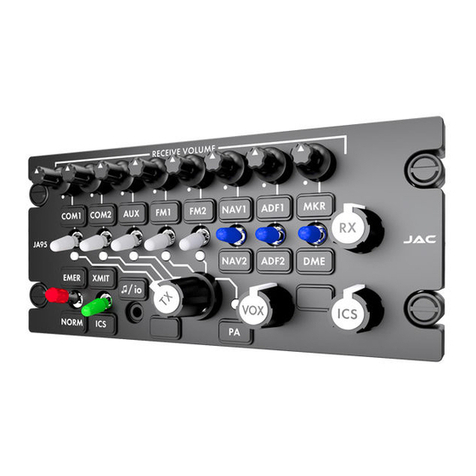
Jupiter Avionics J301A-001 User manual

Rev B Page i
J301A-001
Audio Controller
Installation and Operating Manual
Rev A
Jupiter Avionics Corporation
1959 Kirschner Road
Kelowna BC
Canada V1Y 4N7
Tel: +1 778 478 2232
Toll-Free: 1 855 478 2232
www.jupiteravionics.com

J301A-001 Audio Controller
Installation and Operating Manual
Rev A Page ii
Copyright 2020 Jupiter Avionics Corp.
All rights reserved
Jupiter Avionics Corporation (JAC) permits a single copy of this manual to be printed or downloaded for the express use
of an installing agency. Any such electronic or printed copy of this manual must contain the complete text of this copyright
notice. Any unauthorized commercial distribution of this manual is strictly prohibited. Except as described above, no part
of this manual may be reproduced, copied, transmitted, disseminated, downloaded, or stored in any storage medium for
any purpose without the express prior written consent of JAC.
RECORD OF REVISIONS
Revision
Rev Date
Description
ECR
A
Jun 2020
Initial release, Serial number 1001 and higher.
2486
Prepared:
DGB
Checked:
Approved:
IMPORTANT:
Information in this document is subject to change without notice.
To confirm the current revision status of this manual, visit the JAC website:
www.jupiteravionics.com
JAC
SRM
07-23-20 JAC
KDV
07-23-20

J301A-001 Audio Controller
Installation and Operating Manual
Rev A Page iii
Table of Contents
SECTION 1 - DESCRIPTION ................................................................................................................................................. 1
1.1 System Overview .................................................................................................................................................... 1
1.2 Features Overview .................................................................................................................................................. 1
1.3 Inputs and Outputs .................................................................................................................................................. 2
1.3.1 Inputs............................................................................................................................................................... 2
1.3.2 Outputs ............................................................................................................................................................ 2
1.3.3 Bi-directional Ports .......................................................................................................................................... 2
1.3.4 Audio Loads .................................................................................................................................................... 2
1.3.5 Grounds........................................................................................................................................................... 3
1.4 Specifications .......................................................................................................................................................... 3
1.4.1 Electrical Specifications................................................................................................................................... 3
1.4.2 Mechanical Specifications ............................................................................................................................... 5
1.4.3 Flammability of Materials ................................................................................................................................ 5
SECTION 2 – INSTALLATION............................................................................................................................................... 6
2.1Introduction.............................................................................................................................................................. 6
2.2 Continued Airworthiness ......................................................................................................................................... 6
2.3 Unpacking and Inspecting Equipment..................................................................................................................... 6
2.3.1 Warranty .......................................................................................................................................................... 6
2.4 Installation Procedures............................................................................................................................................ 6
2.4.1 Installation Limitations ..................................................................................................................................... 6
2.4.2 Cabling and Wiring .......................................................................................................................................... 6
2.4.3 Mechanical Installation .................................................................................................................................... 7
2.4.4 In-Line PTT Cordsets ...................................................................................................................................... 7
2.4.5 Legend Replacement ...................................................................................................................................... 7
2.4.6 Post Installation Checks .................................................................................................................................. 7
2.5 Adjustments and Configuration using ProCS™ ...................................................................................................... 8
2.5.1 Configuration Cabling Requirements .............................................................................................................. 8
2.5.2 ProCS™ Setup................................................................................................................................................ 8
2.5.3 Configurable Settings ...................................................................................................................................... 8
2.5.4 Other Configuration Features........................................................................................................................ 14
2.6 Installation Kit ........................................................................................................................................................ 14
2.6.1 Recommended Crimp Tools ......................................................................................................................... 14
2.7 Installation Drawings ............................................................................................................................................. 14
2.7.1 Generation of Custom Drawings ................................................................................................................... 14
SECTION 3 – OPERATION.................................................................................................................................................. 15
3.1 Introduction............................................................................................................................................................ 15
3.2 Front Panel Controls ............................................................................................................................................. 15
(1) Transceiver Switches, Annunciators and Legends ....................................................................................... 16
(2) Receiver Switches and Legends ................................................................................................................... 16
(3) Music/Configuration Connector (♫/io) ........................................................................................................... 16
(4) Transmit Selector .......................................................................................................................................... 17
(5) EMER Position .............................................................................................................................................. 17
(6) Transmit Annunciator - TX ............................................................................................................................ 17
(7) ICS or RMT Position ..................................................................................................................................... 17
(8) Receive Volume Control ............................................................................................................................... 17
(9) ICS Volume Control....................................................................................................................................... 17
(10) Music and Private Intercom Select Switches (MUS and PVT) ..................................................................... 17
(11) VOX Threshold Control ................................................................................................................................. 18
3.3 Normal Operation Mode ........................................................................................................................................ 18
3.3.1 Panel Lighting................................................................................................................................................ 18
3.3.2 Receiving....................................................................................................................................................... 18
3.3.3 Transmitting (Transmit Operation) ................................................................................................................ 18
3.3.4 VOX Operation .............................................................................................................................................. 18
3.3.5 ICS Operation................................................................................................................................................ 19
3.3.6 COM7 PTT Operation ................................................................................................................................... 19
3.3.7 Music Operation ............................................................................................................................................ 19
3.3.8 COM8 Artificial Sidetone Operation .............................................................................................................. 19

J301A-001 Audio Controller
Installation and Operating Manual
Rev A Page iv
3.4 Emergency Operation Mode ................................................................................................................................. 19
3.4.1 Auto Emergency Mode.................................................................................................................................. 19
3.4.2 Selected Emergency Mode ........................................................................................................................... 19
Appendix A - Installation Drawings...................................................................................................................................A1
A1 Introduction............................................................................................................................................................A1
A2 Installation Drawings .............................................................................................................................................A1
Appendix B - Certification Documents .............................................................................................................................B1
B1 Airworthiness Approval .........................................................................................................................................B2
B2 Instructions for Continued Airworthiness ..............................................................................................................B2

Rev A Page 1
J301A-001 Audio Controller
SECTION 1 - DESCRIPTION
1.1 System Overview
The J301A-001 audio controller is a centralized management system that distributes and controls transceiver,
receiver and warning source audio for one user in an aircraft. It enables the selected transmission of microphone
audio to a transceiver and connects to the intercom audio bus.
The J301A-001 audio controller provides a passive emergency mode that directs the user to the COM 1 transceiver,
NAV1 receiver and all Direct Audio.
The J301A-001 is set up on a per-installation basis using a configuration cable and a PC running the product
configuration tool to download system configuration settings via the front panel music / configuration connector.
1.2 Features Overview
The J301A-001 has a 15 pin D-Min connector, which interfaces to the Direct audio and ICS Tie lines, a 50 pin D-Min
connector which interfaces to the Radios, power and user headset connections, and a 25 pin D-Min connector which
interfaces to music and extra transceivers. This layout follows industry standard interconnects for single-user single
transmit selector audio controllers. The front (faceplate) subassembly contains the user interface.
Numerous input and output levels are adjustable, several audio paths are selectable using the configuration tool
ProCS™ (Product Configuration Software) to write configuration commands via the JA99-001 configuration cable to
the front panel music / configuration connector.
The J301A-001 supports up to eight transceivers, each selectable from a rotary switch.
The J301A-001 supports up to six receivers.
The J301A-001 has intercom VOX operation.
The J301A-001 supports four Direct Audio inputs to provide audio at a fixed level to the user.
The J301A-001 has a CVR output.
A Music / Configuration connector is provided on the faceplate of the J301A-001 for configuration of audio levels and
routing. The connector can also be used as a music input and is compatible with most music players.
The J301A-001 has two modes of operation: Normal Mode and Emergency Mode.

J301A-001 Audio Controller
Installation and Operating Manual
Rev A Page 2
1.3 Inputs and Outputs
Refer to the J301A-001 connector maps for the mating connector designators and pin assignments for the
input and output signals.
1.3.1 Inputs
Name
Qty
Type
COM REMOTE TX SELECT
8
Audio signal (on expansion connector)
CONFIG DATA TO J301A
1
Data signal
CONFIG MODE SELECT
1
Multi format signal
DIRECT AUDIO 1-4 HI/LO
4
Audio signal
DYNAMIC MIC +/-
1
Audio signal
FRONT PANEL MUSIC R/L
2
Audio signal
HI LEVEL MIC HI/LO
2
Audio signal
LIGHTS
1
Analog control signal
MUSIC LEFT/RIGHT HI/LO
4
Audio signal
POWER INPUT
1
Power supply
RX HI
12
Audio signal
RX HI/LO
2
Audio signal (on expansion connector)
USER ICS PTT
1
Active low discrete
USER TX PTT
1
Active low discrete
1.3.2 Outputs
Name
Qty
Type
COM MIC HI
6
Audio signal
COM MIC HI
2
Audio signal (on expansion connector)
CONFIG DATA FROM J301A
1
Data signal
CVR HI/LO
2
Audio signal
COM KEY
6
Active low discrete
COM KEY
2
Active low discrete (on expansion connector)
RX COMPOSITE HI/LO
1
Audio signal
USER 600 OHM PHN
1
Audio signal
USER 8 OHM PHN HI/LO
1
Audio signal
1.3.3 Bi-directional Ports
Name
Qty
Type
INTERCOM AUDIO
1
Audio signal
JAC ICS TIE HI/LO
1
Audio signal
PVT INTERCOM AUDIO HI/LO
1
Audio signal
1.3.4 Audio Loads
Name
Qty
Type
150 OHM LOAD 1 and 2
2
Termination
INTERCOM LOAD
1
Termination
PVT INTERCOM LOAD
1
Termination
RX 600 OHM LOAD
4
Termination

J301A-001 Audio Controller
Installation and Operating Manual
Rev A Page 3
1.3.5 Grounds
Name
Qty
Type
CHASSIS GROUND
1
Airframe ground connection
POWER GROUND
1
Power ground
RX COMMON
1
Audio signal ground
1.4 Specifications
1.4.1 Electrical Specifications
Power Input
Primary nominal voltage 28 Vdc
Secondary nominal voltage 14 Vdc
Maximum voltage 32.2 Vdc
Minimum voltage 10.2 Vdc
Emergency voltage ≤9.0 Vdc
Input current at 28 Vdc ≤ 0.7 A
Input current at 14 Vdc ≤ 1.4 A
Input current at 9 Vdc ≤ 2.4 A
1.4.1.1 Audio Performance
Rated Input Level
Receive audio rated input level 4.5 Vrms ±10%
Direct audio rated input level 4.5 Vrms ±10%
Music rated input level 400 mVrms ±10%
HI level Microphone input level 250 mVrms ±10%
Dynamic Microphone input level 250 uVrms ±10%
JAC ICS Tie Line type 1 input level 340 mVrms ±10%
JAC ICS Tie Line type 2 input level 1.20 Vrms ±10%
Interphone input level 2.80 Vrms ±10%
PVT Interphone input level 2.80 Vrms ±10%
Rated Output Level
600 OHM PHONE rated output 12.3 Vrms±10%
8 OHM PHONE rated output 1.42 Vrms±10%
600 OHM PHONE rated output,
in emergency mode or with power input ≤6 Vdc 2.10 Vrms±10%
600 OHM PHONE rated output power,
with MUSIC input 6.14 Vrms±10%
600 OHM PHONE rated output power, in Emergency mode
or with power input <= power off voltage 3.0 Vrms±10%
COM MIC rated output 250 mVrms±10%
CVR rated output 500 mVrms±10%
CVR rated output with input as MUSIC 250 mVrms±10%
CVR rated output with input as HI LEVEL MIC 1.00 Vrms±10%
CVR rated output, in emergency mode, 500 mVrms ±10%
RX Composite rated output 2.50 Vrms ±10%
JAC ICS Tie type 1 rated output 340 mVrms ±10%
JAC ICS Tie type 2 rated output 1.20 Vrms ±10%
INTERPHONE rated output 2.80 Vrms ±10%
PVT INTERPHONE rated output 2.80 mVrms ±10%
Audio Frequency Response
Audio output audio frequency response ≤3dB from 300 to 6000 Hz

J301A-001 Audio Controller
Installation and Operating Manual
Rev A Page 4
Distortion Characteristics
Audio output distortion at rated power ≤10% THD + N
Input Impedance
HI LEVEL MIC input Impedance 150 Ω±10%
DYNAMIC MIC input Impedance 5 Ω±40%
Direct Audio input Impedance 10 kΩ±10%
Receive Audio input Impedance 10 kΩ±10%
Music Audio input Impedance 1000 Ω±10%
JAC ICS TIE 2000 Ω±10%
INTERCOM Audio input Impedance 19 kΩ±10%
PVT INTERCOM Audio input Impedance 19 kΩ±10%
Output Load
600 OHM PHN load 600 Ω±10%
8 OHM PHN load 8 Ω±10%
COM MIC load 150 Ω±10%
CVR load 5000 Ω±10%
RX Composite Audio load 600 Ω±10%
JAC ICS TIE type 1 rated load 2000 Ω±10%
JAC ICS TIE type 2 rated load 2000 Ω±10%
INTERCOM rated load 600 Ω±10%
PVT INTERCOM rated load 600 Ω±10%
JAC ICS TIE type 1 maximum load 666 Ω±10%
JAC ICS TIE type 2 maximum load 285 Ω±10%
Volume Controls
Receive Audio control variation 32 ±3dB
ICS Audio control variation 42 ±3dB
Input to Output Crosstalk and Bleed-through Level
Input to Output crosstalk ≤55 dB
Input to Input Crosstalk Level
Input to Input crosstalk ≤60 dB
Audio Noise Level without Signal
Noise level below the rated output ≥60 dB
1.4.1.2 Audio Performance, Other
CVR HI / LO output circuitry type (Normal) differential
CVR HI / LO output circuitry type (Emergency) single ended
HI LEVEL MIC inputs designed for MIC type amplified dynamic /electret
DYNAMIC MIC inputs designed for MIC type 5 ohm dynamic
HI LEVEL MIC inputs circuitry single ended
MUSIC LEFT / RIGHT HI / LO audio input circuitry type differential
FRONT MUSIC LEFT / RIGHT audio input circuitry type: single ended
MUSIC attenuation 38 dB max
RECEIVE AUDIO input circuitry type differential
600 OHM PHN HI / LO output circuitry type balanced
8 OHM PHN HI / LO output circuitry type balanced
MIC output circuitry type single ended
RX Composite Audio output circuitry type differential
ICS TIE HI / LO Circuitry Type differential

J301A-001 Audio Controller
Installation and Operating Manual
Rev A Page 5
INTERCOM HI / LO Circuitry Type single ended
PVT INTERCOM Circuitry Type single ended
Fade-in duration for PHN Audio output music signal 2.5 ±1.0 s
VOX Threshold control range -30 to +12 dB
VOX Off Delay Time accuracy shall be ± 0.25 s
Receive Audio detect threshold control range, relative to
rated receive audio input -36 to -12 dB
1.4.1.4 Discrete Signals
Active low control input, active signal level ≤+3 Vdc
Active low control input, inactive signal level ≥+10 Vdc
Active low control input, current 0.1 to 10 mA
Active low control output, active output ≤+2 Vdc
Active low control output, active, current ≤1 A
1.4.1.5 Lights Input
LIGHTS INPUT ranges 0 to 28, 0 to 14 and 0 to 5 Vdc
LIGHTS INPUT current ≤10 mA max.
1.4.2 Mechanical Specifications
Height 2.625 in [67.7 mm] max
Behind panel depth 3.42 in [86.9 mm] max
Faceplate width 5.75 in [146 mm] max
Behind panel width 4.92 in [125 mm] max
Weight 1.64 lb [0.74 kg] max
Material brushed aluminum with conversion
coating
Connectors (5): Main J1 One 50-pin D-Sub male
Direct Audio J2 One 15-pin D-Sub male
Expansion J3 One 25-pin D-Sub male
Music/Configuration J4 One 4 pole 3.5mm stereo jack
Chassis Ground J5 One 4-40 stud
Mounting 4 Dzus fasteners
Bonding ≤2.5 mΩ
Installation kit part number INST-J301A
Faceplate white legends on black
1.4.3 Flammability of Materials
The J301A-001 complies with the requirements of RTCA/DO-160G Sec 26.3.3 "Flammability", through equivalent
flammability testing of materials and the Small Parts Exemption.

Rev A Page 6
J301A-001 Audio Controller
SECTION 2 – INSTALLATION
2.1 Introduction
This section contains unpacking and inspection procedures, installation information, and post-installation checks.
2.2 Continued Airworthiness
Maintenance of the J301A-001 is on condition only. Scheduled inspection and/or periodic maintenance of this unit is
not required.
2.3 Unpacking and Inspecting Equipment
Unpack the equipment carefully. Check for shipping damage and report any problems to the relevant carrier. Confirm
that the Authorized Release Certificate or Certificate of Conformance is included. Complete the on-line warranty card
from the Jupiter Avionics Corporation (JAC) website - www.jupiteravionics.com/warrantyregistration
2.3.1 Warranty
This product manufactured by JAC is warranted to be free of defects in workmanship or performance for 2 years from
the date of installation by an approved JAC dealer or agency. This warranty covers the cost of all materials and labour
to repair or replace the unit, but does not include the cost of transporting the defective unit to and from JAC or its
designated warranty repair centre, or of removing and replacing the defective unit in the aircraft. This warranty does
not cover failures due to abuse, misuse, accident, or unauthorized alteration or repairs.
THIS WARRANTY IS VOID IF THE PRODUCT IS NOT INSTALLED BY AN AUTHORIZED JAC DEALER. If the on-
line warranty card is not completed, the product will be warranted from the date of manufacture.
Contact JAC for return authorization, and for any questions regarding this warranty and how it applies to your unit(s).
JAC is the final arbiter concerning warranty issues.
2.4 Installation Procedures
WARNING: Loud noise can cause hearing damage. Set the headset volume to minimum before
conducting tests, and slowly increase the volume to a comfortable listening level.
CAUTION: The power input circuitry of the unit may be damaged if the installation does not conform to the
wiring instructions in this manual.
2.4.1 Installation Limitations
Those installing the J301A, on or in a specific type or class of aircraft, must determine that the aircraft installation
conditions meet standards. The J301A may be installed only by following the applicable airworthiness requirements.
2.4.2 Cabling and Wiring
All wire shall be selected in accordance with the original aircraft manufacturer’s maintenance instructions, or AC43.13-
1B Change 1, Paragraphs 11-76 through 11-78. Unshielded wire types shall qualify to MIL-W-22759 as specified in
AC43.13-1B Change 1, Paragraphs 11-85, 11-86, and listed in Table 11-11. For shielded wire applications, use Tefzel
MIL-C-27500 shielded wire with tag ring or equivalent (for shield terminations) to make the most compact and easily
terminated interconnect. Follow the Connector Map in Appendix A of this manual.

J301A-001 Audio Controller
Installation and Operating Manual
Rev A Page 7
Allow 3” from the end of the shielded wiring to the shield termination to allow the connector hood to be easily installed.
Refer to the Interconnect drawing in Appendix A of this manual for shield termination details. Note that this unit has a
‘clamshell’ hood that is installed after the wiring is complete.
Maintain wire segregation and route wiring in accordance with the original aircraft manufacturer’s maintenance
instructions.
Unless otherwise noted, all wiring shall be a minimum of 24 AWG, except power and ground lines, which shall be a
minimum of 22 AWG. Refer to the Interconnect drawing for additional specifications. Check that the ground
connection is clean and well secured, and that it shares no path with any electrically noisy aircraft accessories such
as blowers, turn-and-bank instruments, or similar loads.
2.4.3 Mechanical Installation
The J301A-001 can be mounted in any attitude and location with adequate space for the front panel and sufficient
clearance for the connector and wiring harness. It requires no direct cooling.
2.4.4 In-Line PTT Cordsets
If in-line PTT cordsets (drop cords) are used, be aware that incorrectly configured or improperly shielded in-line PTT
cordsets can lead to significant audio problems.
2.4.5 Legend Replacement
The J301A-001 illuminated legends are field replaceable. For further information, refer to the Legend Replacement
document in Appendix A of this manual.
2.4.6 Post Installation Checks
2.4.6.1 Voltage/Resistance checks.
Do not attach this unit until the following conditions are met:
a) Check P1 pin 50 for lights buss voltage.
b) Check P1 pin 12 for +28 Vdc power.
c) Check P1 pin 11 for continuity to ground (less than 0.5 Ω).
d) Check P2 pins 6and 7 for continuity to ground (less than 0.5 Ω) when the relevant switch is closed.
e) Check P3 pins 9 to 13 and 22 to 24 for continuity to ground (less than 0.5 Ω) when the relevant switch is
closed.
f) Check all pins for shorts to ground or adjacent pins.
2.4.6.2 Configuration
Ensure that the J301A contains the correct configuration settings. This may be done at the factory, on the
maintenance bench or in the aircraft before the power on checks are performed. Refer tosection 2.5.
2.4.6.3 Power on Checks.
Power up the aircraft’s systems and confirm normal operation of all functions of the J301A. Refer to
Section 3 (Operation) for specific operational details.
a) Begin with only the user’s headset attached. Confirm correct ICS and radio operation for both receive and
transmit. Check yoke or cyclic switch action. Check the radio selection and inputs. Do not proceed until the
radios are functioning correctly.
b) If there is a music source in the system, turn it on and check for proper mute operation.
c) Unusual buzzes, hums or other background audio are symptomatic of multiple grounds, or noisy external
systems such as blowers or pumps sharing wiring with the audio system. If a transmitter fails to key or
correctly modulate it is often the result of not connecting all required grounds to the radio or external audio
system.
d) Check the ICS operation and Emergency operation.

J301A-001 Audio Controller
Installation and Operating Manual
Rev A Page 8
e) Check that all configurations settings are correct.
When all performance checks are satisfied, complete the necessary regulatory documentation before releasing the
aircraft for service. Refer to Appendix B.
2.5 Adjustments and Configuration using ProCS™
All the J301A-001 internal adjustments are set from the Product Configuration Software ProCS™. Configuration data
is sent to the J301A-001 via the front panel connector (♫/io), using the Configuration Cables and a computer running
the ProCS™ software. For configuration requirements, see section 2.5.1.
For full information on the configuration process, and for installation of ProCS™ on your computer, refer to the
ProCS™ manual on the Jupiter Avionics website - www.jupiteravionics.com/productsoftware.
2.5.1 Configuration Cabling Requirements
To configure the J301A-001, it is necessary to load the Product Configuration Software ProCS™ onto a Windows-
based computer as described in the ProCS™ manual.
The cables required to configure the J301A-001 are not included with the unit.
Cabling option 1:
Quantity Description J301A-001
1 USB A to RS232 9-Pin Cable CAB-USB-0002
1 Configuration Cable JA99-001
Cabling option 2:
Quantity Description J301A-001
1 USB A Male to RS232 3.5mm Plug CAB-USB-0006
2.5.2 ProCS™ Setup
The ProCS™ J301A-001 menu item 'ProCS Setup' provides Setup drawings showing the cabling
arrangement for connecting the J301A-001 to a computer running the ProCS™.
2.5.3 Configurable Settings
A standard unit is shipped from the factory with all internal adjustments configured to the default levels. At installation,
it may be desirable to change some of these settings to suit the local operating environment.
Note: To properly configure the J301A-001, power must be applied, and the TX Select switch must be in the
COM1 to COM8 or ICS position (not EMER).
Within ProCS™, the configurable settings are grouped together into the following sections:

J301A-001 Audio Controller
Installation and Operating Manual
Rev A Page 9
2.5.3.1 Front Panel Switches
2.5.3.2 Radios
The Front Panel Switches window is used to specify the text for each legend.
The Radios window is used to define the radios for the transceivers and receivers.

J301A-001 Audio Controller
Installation and Operating Manual
Rev A Page 10
2.5.3.3 Receive Levels
The level of the receive composite audio output (RX COMP OUT)
can be adjusted from 0.25 to 2.5 Vrms. (Default 1.0 Vrms)
The Receive Audio Detector threshold can be adjusted
from -36 to -12 dB of rated input level. (Default -24 dB)
The receive and direct audio input level of each of the
eighteen RX and DIRECT AUDIO inputs can be adjusted
from 1 to 10 Vrms. (Default 7.75 Vrms)

J301A-001 Audio Controller
Installation and Operating Manual
Rev A Page 11
2.5.3.4 Transmit Levels
2.5.3.5 Sidetone Levels
The level of each of the eight Transceiver MIC output
signals can be adjusted from 0.01 to 1 Vrms.
When the Remote TX Select box ischecked the ICS TX select position becomes
t
he remote TXSelect (RMT ). (Default not checked) (see section 3.2 (7))
The Receive Sidetone Level can be adjusted from
0 to -12 dB of the rated phone Level. (Default -6 dB)
The level of the COM8 Artificial Sidetone can be adjusted
from 0 to -30 dB of the rated phone Level. (Default -10 dB)
When the COM7 Duplex box is checked the COM7 radio is set to duplex operation
(Default not checked) (see section 3.3.4)

J301A-001 Audio Controller
Installation and Operating Manual
Rev A Page 12
2.5.3.6 Connector Pin Configuration
Several of the connector pins can be configured to meet the requirements of specific installations. Refer to
J301A-001 Interconnect sheet 4 of 4.
2.5.3.7 Audio Muting (During Transmit)
When the Mute RX Audio check box is checked the
Receive Audio is muted during transmit (Default
checked)
When the Mute ICS Audio check box is checked the
ICS Audio is muted during transmit (Default checked)
2.5.3.8 CVR Level
The level of the Cockpit Voice Recorder audio may be adjusted from 0.01 to 1 Vrms. (Default 500 mVrms)

J301A-001 Audio Controller
Installation and Operating Manual
Rev A Page 13
2.5.3.9 Music Levels
2.5.3.10 ICS Tie Line
The rated input and output levels of the intercom tie line can be selected as Type 1, Type 2 or Andrea
(Default Type 2).
The quantity of external loads for a type1 intercom tie line can be selected from 0 to 3 (Default 0).
The quantity of external loads for a type 2 intercom tie line can be selected from 0 to 7 (Default 0).
2.5.2.11 Lighting Voltage Selection
The rated input level for the lighting voltage may
be selected from
+5 Vdc, +14 Vdc or +28Vdc
(Default +28 Vdc).
The music output level of the four Music input signals to the Phones audio
can be adjusted from -40 to 0 dB of rated phone level (Default 0 dB).
The attenuation level during muting of the music signal can be
adjusted from 0 to -40 dB (Default -40 dB).

J301A-001 Audio Controller
Installation and Operating Manual
Rev A Page 14
2.5.3.12 VOX
2.5.2.13 Connector Maps
This section contains connector maps and interconnects that are automatically generated to show changes that
affect the installation of the J301A-001, such as switch labels and voltages. See section 2.7.1.
2.5.4 Other Configuration Features
In the J301A-001 Product Information Window, the model number, serial number and check sum of the J301A-001
audio panel can be viewed.
2.6 Installation Kit
The kit required to install this unit is not included with the unit.
The installation kit (Part # INST-J301A) consists of the following:
Quantity
Description
JAC Part #
1
25 Socket Positions, Zinc Plated, D-Sub - Crimp Socket Housing
CON-3460-0125
1
50 Socket Positions, Zinc Plated, D-Sub - Crimp Socket Housing
CON-3460-0150
1
15 Pin Clamshell, Hardware - Plastic D-Sub Hoods
CON-5300-0115
1
25 Pin Clamshell, Hardware - Plastic D-Sub Hoods
CON-5300-0125
1
50 Pin Clamshell, Hardware - Plastic D-Sub Hoods
CON-5300-0150
90
Machined 20 - 24 AWG, MIL spec, D-Sub - Crimp Socket
CON-3320-2024M
3
D-Sub 4-40, Hardware - Jack Screws
CON-5150-0440
2
0.375" Inside Diameter, Hardware - Tag Ring
CON-5500-0375
1
0.625" Inside Diameter, Hardware - Tag Ring
CON-5500-0625
1
1" Inside Diameter, Heat Shrink Tube
WIR-HTSK-1000
2
3/4" Inside Diameter - Black, Heat Shrink Tube
WIR-HTSK-0750
2.6.1 Recommended Crimp Tools
Standard D-Sub Crimp Tool Chart
Tool Type
Hand crimping tool
Positioner
Insertion/extractor tool
POSITRONIC
9507-0-0-0
9502-5-0-0
4711-2-0-0
DANIELS
AFM 8
K13-1
91067-2
MIL-SPEC
M22520/2-01
M22520/2-08
M81969/1-02
2.7 Installation Drawings
The drawings and documents required for Installation can be found in Appendix A of this manual.
2.7.1 Generation of Custom Drawings
The interconnects and connector maps in Appendix A of this manual are generic drawings based on the standard
version of the J301A-001. However, if a unit has been configured using JAC’s ProCS™ software to change switch
legends or lighting voltages, the software can be used to generate fully customized interconnects and connector
maps for use by the installer.
The VOX OFF Delay Time can be adjusted
from 0.50 to 2.00 sec (Default 1 sec).

Rev A Page 15
J301A-001 Audio Controller
SECTION 3 – OPERATION
3.1 Introduction
This section contains the operating instructions for the J301A-001.
3.2 Front Panel Controls
Note: The 19 legends and one deadfront annunciator are removable and may be replaced with custom
ordered parts. The controls will be referred to by the default legend and annunciator names as shown below.
1. Transceiver switches,annunciators and associated legends
2. Receiver switches and associated legends
3. Music/configuration input connector and legend
4. Transmit selector
5. EMER legend
6. Transmit annunciator (deadfront)
7. ICS / RMT Control
8. Receive volume control
9. ICS volume control
10. Music and Private Intercom select switches
11. VOX threshold control
3
6
5
4
8
1
9
2
10
11
7

J301A-001 Audio Controller
Installation and Operating Manual
Rev A Page 16
(1) Transceiver Switches Annunciators and Legends
These are eight white two-position toggle
switches grouped around the TX selector
control. When a switch is set to the ‘up’
position (towards the legend), audio from
the associated transceiver is routed to the
phones.
Legend
Switch
Annunciator
The legends (above the switches) are
interchangeable to allow customization.
(Default – COM1to COM8)
Note: For information on the ICS and EMER switches, refer to (5) and (7) below.
(2) Receiver Switches and Legends
These are six blue two-position toggle switches. When a
switch is set to the ‘up’ position (towards the legend)
audio from the selected receiver is routed to the phones.
The legends are interchangeable to allow customization.
(Default – NAV1, NAV2, ADF1, ADF2, DME and MKR.)
(3) Music/Configuration Connector (♫/io)
(This connector is also used during installation to change configuration settings.)
CAUTION: If an unapproved connector or cable is used, damage to the unit or to any attached device may
occur. If in doubt, contact your installing agency.
This is a music input that is compatible with
most music players. It accepts a 3 pole 3.5mm
stereo plug with a slim diameter connector
housing.
The port (♫/io) is protected by a urethane rubber cover,
which can be lifted upwards or rotated round (as shown)
to provide access to the port.
Legend
♫/io Port
Port Cover
Table of contents
Other Jupiter Avionics Controllers manuals
Popular Controllers manuals by other brands

EGS
EGS Sola Hevi Duty MCR Installation and operation manual

Carel
Carel mastercella Technical leaflet

Fuji Electric
Fuji Electric FRENIC-EcoPAK instruction manual

Felicitysolar
Felicitysolar MPPT user guide

Scanivalve
Scanivalve ECM4000 Hardware and software manual

Avid Technology
Avid Technology Artist Transport user guide