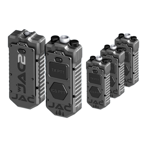
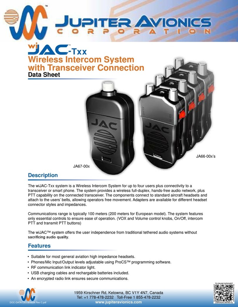
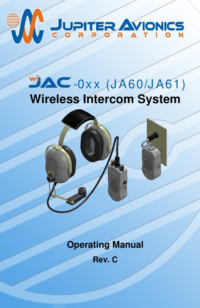
Jupiter Avionics JAC-T Series User manual

Page 1
-Txx (JA66/JA67)
Wireless Intercom System
with Transceiver Connection
Operating Manual
Rev. B

wiJAC-Txx Wireless Intercom System with Transceiver Connection
Operating Manual
Page i
IMPORTANT:
Information in this manual is subject to change
without notice.
To check the current revision status of
this manual, visit the JAC website:
www.jupiteravionics.com
Copyright 2014 Jupiter Avionics Corp.
All rights reserved
Jupiter Avionics Corporation (JAC) permits a single copy of this manual to be
printed or downloaded for personal use. Any such electronic or printed copy of
this manual must contain the complete text of this copyright notice. Any
unauthorized commercial distribution of this manual is strictly prohibited. Except
as described above, no part of this manual may be reproduced, copied,
transmitted, disseminated, downloaded, or stored in any storage medium for any
purpose without the express prior written consent of JAC.
Record of Revisions
Rev Date Description ECR
A May 2014 Initial release, serial number 1001 + 2914
3622
B Jun 2016 Add Freq and RF; change drawing.
Prepared:
MPB
Checked:
Approved:
JAC
MB
06-27-16 JAC
KDV
06-27-16

wiJAC-Txx Wireless Intercom System with Transceiver Connection
Operating Manual
Page ii
Table of Contents
1 Introduction ................................................................................................ 1
1.1 Unpacking ................................................................................................ 2
1.2 Verify Operating Region ........................................................................... 2
2 JA66-00x Headset Adapter (JA66) ............................................................ 3
3 JA67-00x Transceiver Adapter (JA67)...................................................... 3
4 Controls, Annunciators and Connectors ................................................. 4
4.1 (ON/OFF) Button – Both units .............................................................. 4
4.2 Controls – JA66 ........................................................................................ 4
4.2.1 VOX (Voice Operated Switch) ........................................................ 4
4.2.2 VOL (Phones Volume Control) ....................................................... 4
4.2.3 ICS PTT (Push To Talk) Button ...................................................... 4
4.2.4 TX PTT (Push To Talk) Button ....................................................... 4
4.3 Headset Jack – JA66 ................................................................................ 5
4.4 Transceiver Connector – JA67 ................................................................. 5
4.5 Connectors – Both units ........................................................................... 5
4.5.1 IO Configuration Port (Dealers only) ............................................... 5
4.5.2 PWR (Charging Port) ...................................................................... 5
4.6 Annunciators – Both Units ........................................................................ 5
4.6.1 PWR ON (Power On) ..................................................................... 5
4.6.2 LOW BATT (Low Battery Warning) ................................................ 5
4.6.3 Battery Charge (not shown) ............................................................ 6
4.7 Other ........................................................................................................ 6
4.7.1 Pairing Registration Number ........................................................... 6
4.7.2 Battery Lid Release ........................................................................ 6
4.7.3 Clothing/Mounting Clip ................................................................... 6
5 Pairing and Purging Process .................................................................... 7
5.1 Pairing ...................................................................................................... 7
5.2 Purging ..................................................................................................... 8
6 Connecting the wiJAC™ System.............................................................. 9
6.1 wiJAC-Txx System with non-Aircraft Radio .............................................. 9
6.2 wiJAC-Txx System connected to Aircraft Audio System ......................... 10
6.3 wiJAC™ Set-up and Connection ........................................................... 11
6.3.1 Insert Batteries ............................................................................. 11
6.3.2 Attach JA66 Headset Adapter and JA67 Transceiver Adapter ..... 11
6.3.3 Turn On Paired Adapters and Verify Connection .......................... 11
6.3.4 Verify System Audio Operation ..................................................... 11

wiJAC-Txx Wireless Intercom System with Transceiver Connection
Operating Manual
Page iii
6.4 wiJAC™ System Operation ................................................................... 12
6.4.1 System Overviews ........................................................................ 12
6.4.2 Listening Operation ...................................................................... 12
6.4.3 VOX Speaking Operation ............................................................. 12
6.4.4 TX PTT or ICS PTT Speaking Operation ...................................... 12
6.4.5 Live Speaking Operation .............................................................. 12
6.4.6 Low Battery Warning .................................................................... 12
6.4.7 Operation during Charging ........................................................... 12
6.4.8 Loss of Audio ................................................................................ 13
6.4.9 Battery Life ................................................................................... 13
7 Batteries.................................................................................................... 14
7.1 Inserting or Replacing the Batteries........................................................ 14
7.2 Charging Batteries in the Unit ................................................................. 14
7.3 Charging Operation – via Battery Charger ............................................. 15
7.4 Battery Cautions and Warnings .............................................................. 15
8 Accessories.............................................................................................. 16
8.1 Adapter Cables ....................................................................................... 16
8.2 JA72-005 Glove Box with USB connector .............................................. 16
8.3 ProCS™ Product Configuration Software ............................................... 16
8.4 Battery Charger Recommendations ....................................................... 16
9Specifications........................................................................................... 17
9.1 Mechanical ............................................................................................. 17
9.2 Electrical ................................................................................................. 17
9.3 Environmental......................................................................................... 17
9.4 Other ...................................................................................................... 17
10 Warranty.................................................................................................... 18
11 FCC Compliance Statement .................................................................... 18

wiJAC-Txx Wireless Intercom System with Transceiver Connection
Operating Manual
Rev B Page 1
1 Introduction
This manual contains the operating instructions for the wiJAC-Txx Wireless
Intercom System with Transceiver Connection. The diagram below describes the
naming method for the different systems.
wiJAC-T x x
North America:
The wiJAC-Tx1 consists of one JA67-001 Transceiver Adapter, and up to four
JA66-001 Headset Adapters.
RF output power is 21dBm (125mW peak)
Channel frequencies 23 = 1.921536 GHz
24 = 1.923264 GHz
25 = 1.924992 GHz
26 = 1.926720 GHz
27 = 1.928448 GHz
Europe:
The wiJAC-Tx2 consists of one JA67-001 Transceiver Adapter, and up to four
JA66-001 Headset Adapters.
RF output power is 23 dBm (200 mW peak)
Channel frequencies 9 = 1.881792 GHz
8 = 1.883520 GHz
7 = 1.885248 GHz
6 = 1.886976 GHz
5 = 1.888704 GHz
4 = 1.890432 GHz
3 = 1.893888 GHz
2 = 1.896616 GHz
1 = 1.895616 GHz
0 = 1.897344 GHz
Only paired units will operate together (see section 5)
System operating information is in section 6.4.
WARNING: JAC recommends that no battery operated device
should be relied upon as the sole method of communication in
cases where there is potential risk to life or limb.
Number of Headsets
in the System (2 – 4)
Operating Region:
1 = N America
2 = Europe
System Type:
T = Transceiver

wiJAC-Txx Wireless Intercom System with Transceiver Connection
Operating Manual
Rev B Page 2
1.1 Unpacking
Unpack the wiJAC™ box carefully, and ensure that it contains the following:
• one Wireless Aircraft Transceiver Adapter, JAC P/N JA67-00x
• Two to four Wireless Aircraft Headset Adapters, JAC P/N JA66-00x
• one set of AAA rechargeable batteries for each unit
• one USB to Micro USB cable, JAC P/N CAB-USB-0003 for each unit.
• one wiJAC™ Quick Start Guide, JAC P/N DOC-GUID-WITXXU
1.2 Verify Operating Region
The wiJAC-Txx Wireless Intercom System operates using radio frequencies that
are authorized by government regulatory agencies. Ensure the region in which
you are operating the units matches the region marked on a label on the back of
each unit.

wiJAC-Txx Wireless Intercom System with Transceiver Connection
Operating Manual
2 JA66-00x Headset Adapter (JA66)
Note: The units are shown in grey for clarity
3 JA67-00x Transceiver Adapter (JA67)
ON/OFF Control
Charging Port
LOW BATT
Annunciator (red)
Battery Lid
Release
Push To Talk Buttons
Configuration Port
PWR ON
Annunciator (green)
Headset Jack
VOL
(Phones Volume
Control)
VOX
(Voice Operated
Switch Control)
Clothing
Clip
Fig 2-1, JA66 Right Side View Fig 2-2, JA66 Left Side View
Fig 2-3, JA66 Top View
ICS PTT
(Blue Button
)
TX PTT
(Red Button)
PWR ON Annunciator (green)
Fig 3-1, JA67 Right Side View
Configuration
Port
LOW BATT
Annunciator (red)
Battery Lid Release
Transceiver
Connector
ON/OFF Control
Mounting
Clip
Fig 3-2, JA67 Left Side View
Charging Port

wiJAC-Txx Wireless Intercom System with Transceiver Connection
Operating Manual
Rev B Page 4
4 Controls, Annunciators and Connectors
4.1 (ON/OFF) Button – Both units
The ON/OFF control is a push button switch marked with the symbol and is
located on the left side of the unit. To turn the unit on, press the ON/OFF button
once. To turn the unit off, press and hold the ON/OFF button until the PWR ON
and LOW BATT annunciators turn off (approximately three to five seconds).
4.2 Controls – JA66
4.2.1 VOX (Voice Operated Switch)
The Voice Operated Switch control is a rotary knob marked VOX located on the
top of the JA66 Headset Adapter. To reduce the level of the sound needed to
route the microphone audio to the Transceiver Adapter, turn the VOX knob
counterclockwise. To increase the level of the sound needed to route the
microphone audio to the Transceiver Adapter, turn the VOX knob clockwise.
Adjust this setting for proper VOX operation as ambient noise levels change.
4.2.2 VOL (Phones Volume Control)
WARNING: Loud noise can cause hearing damage. Before using the
headset, set the volume to minimum, and then slowly increase it to a
comfortable listening level.
The volume control is a rotary knob marked VOL (volume) located on the top of
the JA66 Headset Adapter. To reduce the volume of the audio heard in the
headset rotate the VOL knob counterclockwise. To increase the volume of the
audio heard in the headset rotate the VOL knob clockwise.
4.2.3 ICS PTT (Push To Talk) Button
The intercom Push To Talk button is a blue convex push button switch located on
the right side of the JA66 Headset Adapter. The ICS PTT markings are located
on the back and front of the unit. When the ICS PTT button is pressed and held,
the VOX threshold is overridden, and microphone audio is routed to the paired
JA67 Transceiver Adapter(s).
4.2.4 TX PTT (Push To Talk) Button
The Transmit Push To Talk button is a red cylindrical push button switch on the
left side of the JA66 Headset Adapter. The TX PTT marking is located on the
front and back of the unit. When the TX PTT button is pressed and held,
microphone audio is routed to the Transceiver Adapter and the TX Key output is
activated. (See sections 6.1 and 6.2 for audio routing details.)
This is the user’s Transmit ‘Push-to-talk’ (TX PTT) button. While this button is
pressed, the wiJAC-D01 system will allow the user to transmit on the connected
transceiver. If the TX PTT button is used, the VOX threshold will be overridden
(see section 4.2.1 above).
wiJAC-Txx Wireless Intercom System with Transceiver Connection
Operating Manual
Rev B Page 5
4.3 Headset Jack – JA66
The headset jack is a TJT120 type connector on the top of the JA66 headset
adapter. Insert a U-174/U or U93A/U type Headset plug into the JA66 Headset
Adapter headset jack.
4.4 Transceiver Connector – JA67
The JA67 Transceiver Adapter has a Female 6 Pin SR30-10R-6S (71) jack which
is connected to the transceiver via a suitable cable (see sections 6.1 and 6.2).
4.5 Connectors – Both units
4.5.1 IO Configuration Port (Dealers only)
This port is used by Approved dealers and installers to connect the unit to a
laptop or PC to enable configuration changes using the ProCS™ program.
4.5.2 PWR (Charging Port)
The Charging Port is a Micro-USB connector with a flexible cover labeled PWR
(power) on the left side of the unit. To charge NiMH batteries, connect a USB
(Universal Serial Bus) to Micro USB cable from the Charging Port to a USB
power source.
WARNING: Charging battery types other than NiMH or NiCad may
cause the batteries to leak or explode and cause damage or injury. If
non-NiMH or non-NiCad batteries are installed, do not connect the
Charging Port to a USB power source.
4.6 Annunciators – Both Units
4.6.1 PWR ON (Power On)
The power on (PWR ON) annunciator is a green LED located on the right side of
the unit. In addition to indicating that the unit is turned on, this annunciator
indicates the connection status of paired units (see section 5.1)
4.6.2 LOW BATT (Low Battery Warning)
The low battery (LOW BATT) annunciator is a red LED located on the left side of
the unit. When a unit is turned on, the LOW BATT annunciator will illuminate for 2
seconds.
When the JA66 battery voltage is low the LOW BATT annunciator will flash once
every 1.5 s and a low battery notification (a triple beep) will be heard in the
headphones once every minute. (A similar but higher pitched tone will be heard if
the paired Transceiver Adapter battery charge is low.)
When the unit battery charge is less than or equal to the critical battery voltage,
the unit will turn off.

wiJAC-Txx Wireless Intercom System with Transceiver Connection
Operating Manual
Rev B Page 6
4.6.3 Battery Charge (not shown)
The JA66 and JA67 each have two LED Battery Charge annunciators, one on
each side of the charging port under the flexible dust cover marked PWR.
The Fast Charge annunciator is a red light emitting diode (LED) that will
illuminate when the batteries are being charged at the maximum charge current.
The Top-Off Charge annunciator is a green LED that will illuminate when Fast
Charge mode is complete and the batteries are charged.
4.7 Other
4.7.1 Pairing Registration Number
The pairing registration number is marked on a label in on the back of the JA67.
JA66 Headset Adapters must be marked with the same pairing registration
number after pairing (see section 5.1).
4.7.2 Battery Lid Release
The battery lid release is a lever on the front of the unit recessed into the battery
lid (see section 6.1).
4.7.3 Clothing/Mounting Clip
The clothing clip is on the rear of the JA66 Headset Adapter, and the mounting
clip is on the rear of the JA67 Transceiver Adapter. Ensure that the units are
attached securely.
WARNING: To avoid loss of communication, always charge
rechargeable batteries before every use.

wiJAC-Txx Wireless Intercom System with Transceiver Connection
Operating Manual
Rev B Page 7
5 Pairing and Purging Process
The wiJAC-Txx Wireless Intercom Systems consist of one JA67 Transceiver
Adapter, and up to four factory-paired JA66 Headset Adapters. Any additional
Headset Adapters must be paired with the Transceiver Adapter before the
expanded system can function correctly. Once pairing is complete, the three
character Pairing Registration Number from the back of the JA67 should be
written on the label on the back of each paired JA66 using a permanent marker.
Ensure that the same number is marked on each unit.
To locate the pair switch, the battery cover must be removed from the unit.
5.1 Pairing
The JA66/JA67 pairing process is described in the following steps:
1. Turn off the JA67 and any other JA66 previously paired with the JA67.
2. Turn on the JA67.
The JA67 enters the standby mode (Power Annunciator blinks in sets of
two or three flashes). If the Power Annunciator stays on continuously,
there is a JA66 still powered on and connected to the JA67. Please turn
off the JA66.
3. On the JA67, press and hold the Pair Switch (4 seconds) until the
Power and Low Battery Annunciators start flashing rapidly (10 flashes
/second). Release the Pair switch.
The JA67 enters the pairing mode (Power Annunciator is flashing at a
medium rate (5 flashes /second) and can now be paired with a JA66.
4. Turn on a JA66 to be paired with the JA67.
The JA66 enters the standby mode (Power Annunciator blinks in sets of
two or three flashes).
5. On the JA66, press and hold the Pair Switch (4 seconds) until the
Power and Low Battery Annunciators starts flashing rapidly (10 flashes
/second). Release the Pair switch.
The JA66 enters the pairing mode (Power Annunciator is now flashing at a
medium rate (5 flashes /second) and will complete the pairing process
automatically with the JA67.
When the battery cover is removed,
the pair symbol and switch access
hole can be seen on the edge of the
compartment. Insert a straightened
paperclip into the hole to press the
button.
Switch Access
Pair Symbol

wiJAC-Txx Wireless Intercom System with Transceiver Connection
Operating Manual
Rev B Page 8
The JA66 and JA67 indicate they have completed the pairing process when the
Power Annunciator is on continuously.
5.2 Purging
A JA67 that has already been paired with four JA66 headset adapters must be
purged to clear any existing pairings if it is necessary to replace one or more of
the headset adapters. The purging process is described in the following steps:
1. Turn off the JA67 and any other JA66 previously paired with the JA67.
2. Turn on the JA67.
The JA67 enters the standby mode (Power Annunciator blinks in sets of
two or three flashes). If the Power Annunciator stays on continuously,
there is a JA66 still powered on and is connected to the JA67. Please turn
off the JA66.
3. On the JA67-001, press and hold the Pair Switch (>8 seconds) until the
Power and Low Battery Annunciators turn off. Release the Pair switch.
The JA67 enters the purge mode (Power Annunciator blinks in sets of
three flashes). Wait for the JA67 to finish purging all paired JA67 from its
memory (approximately 10 seconds).
4. Turn off the JA67.
5. Turn on the JA67. If the Power Annunciator blinks in sets of three
flashes, the purging process was successful. If the Power Annunciator
blinks in sets of two flashes, repeat the purging process from step 1.
CAUTION: To minimize the risk of system malfunction, a JA66 must
not be paired with more than one JA67 at a time.

wiJAC-Txx Wireless Intercom System with Transceiver Connection
Operating Manual
Rev B Page 9
6 Connecting the wiJAC™ System
Note: The wiJAC-TxxWireless Intercom System with Transceiver
Connection consists of one JA67 Transceiver Adapter and up to four JA66
Headset Adapters. Only paired units will operate together (see section 5).
The JA67 Transceiver Adapter has a Female 6 Pin SR30-10R-6S (71) jack, and
should be clipped to a suitable secure point. A headset is inserted into the jack
on the JA66 Headset Adapter, which is clipped to the user's belt or clothing.
Headset, audio panel and radio are not included.
6.1 wiJAC-Txx System with non-Aircraft Radio
When connected to a non-aircraft radio, the linked Headset Adapters are in an
intercom loop which allows full duplex communication between the operators of
each JA66. Each operator can listen to the linked radio receive audio, and by
pressing the TX PTT button can transmit on the linked radio in Simplex mode.
When one JA66 is transmitting, all other JA66 mics will be muted, but the
operators can listen to the conversation.
Figure 6-1,
Non-Aircraft Radio System

wiJAC-Txx Wireless Intercom System with Transceiver Connection
Operating Manual
Rev B Page 10
6.2 wiJAC-Txx System connected to Aircraft Audio System
When connected to an aircraft audio system, the linked Headset Adapters are in
an intercom loop which allows full duplex communication between the operators
of each JA66. Each operator can listen to the audio selected for the station to
which the JA67 is connected, and by pressing the TX PTT button on a JA66, can
communicate with the aircraft intercom system in Simplex mode. When one JA66
is communicating, all other JA66 mics will be muted, but the operators can listen
to the conversation.
Note: Communication on this intercom loop is isolated from the aircraft
intercom system unless the TX PTT button on a JA66 is pressed.
Figure 6-2,
Aircraft Audio System

wiJAC-Txx Wireless Intercom System with Transceiver Connection
Operating Manual
Rev B Page 11
6.3 wiJAC™ Set-up and Connection
6.3.1 Insert Batteries
Ensure the batteries for all units are fully charged and installed in the battery
compartment with the correct polarity, and the battery lid is secured (section 6).
6.3.2 Attach JA66 Headset Adapter and JA67 Transceiver Adapter
Insert a headset with a U-174/U or U93A/U type plug into the JA66 Headset
Adapter jack.
Connect the JA67 Transceiver Adapter plug to the required connector using the
appropriate cable (see sections 6.1 and 6.2 for system examples).
6.3.3 Turn On Paired Adapters and Verify Connection
On the JA66 Headset Adapters, turn the VOL knob fully counterclockwise to
minimum. Turn on the JA66 Headset Adapters and the JA67 Transceiver
Adapter. On all units, the PWR ON and LOW BATT annunciators will illuminate
for two seconds.
• When a unit is turned on, the PWR ON annunciator will illuminate for 2
seconds, and the unit will start to search for its paired unit.
• While the unit is searching for its paired unit the PWR ON annunciator will
triple-flash every 1.5 seconds.
• When the unit is connecting to its paired unit, the annunciator wills double-
flash every 1.5 s until connection is established.
• After connection, the annunciator will illuminate steady green until the unit is
turned off.
6.3.4 Verify System Audio Operation
For an aircraft system, set the aircraft audio system's VOX mode to live, or key
the aircraft audio system's ICS PTT for the headset connection used by the JA67
Transceiver Adapter. For non-aircraft radio, increase the radio volume.
Adjust the JA66 Headset Adapter's VOX control to fully counterclockwise and the
VOL control to achieve a comfortable listening level. Confirm that the microphone
audio is live - all microphone audio is heard in the paired JA66 phones. Confirm
that the audio level increases as the VOL control is rotated clockwise and
decreases as the VOL control is rotated counterclockwise.
Adjust the Headset Adapter's VOX control to fully clockwise and confirm that the
microphone audio is off.
Press the Headset Adapter's ICS PTT button and confirm that microphone audio
is heard in the paired JA66 phones. For TX PTT, audio will be heard in the
aircraft audio system or transmitted by the attached radio transceiver.
Adjust the Headset Adapter's VOX control for a comfortable speaking level and
return the audio system's controls to the previous settings.

wiJAC-Txx Wireless Intercom System with Transceiver Connection
Operating Manual
Rev B Page 12
6.4 wiJAC™ System Operation
6.4.1 System Overviews
Refer to section 6.1 for a non-aircraft radio system overview, and to section 6.2
for an Aircraft audio system overview
6.4.2 Listening Operation
The Headset Adapter's Phones Volume (VOL) controls the level of audio heard in
the headset's ear phones. As ambient noise levels change, the volume can be
adjusted.
6.4.3 VOX Speaking Operation
To use the JA66 Headset Adapter hands-free, adjust the VOX control so that the
microphone audio is turned on when speaking into the headset's microphone at a
comfortable level, or at a level to keep the ambient noise from turning on the
microphone audio.
6.4.4 TX PTT or ICS PTT Speaking Operation
To use the JA66 Headset Adapter in high-noise environments, adjust the VOX
control fully clockwise. To communicate, press and hold the JA66 Headset
Adapter's ICS or TX PTT button and speak in to the headset's microphone.
6.4.5 Live Speaking Operation
To use the JA66 Headset Adapter so that the microphone audio is always turned
on, adjust the VOX control fully counterclockwise.
6.4.6 Low Battery Warning
When the unit's battery charge is low, the LOW BATT annunciator will triple flash
every 1.5 seconds. When the JA66 Headset Adapter battery charge is low, a
triple-beep will be heard in the headset once every minute.
Note: JAC recommends that the batteries should be charged or replaced
immediately when the LOW BATT warning illuminates during use.
When the battery charge level is critical, the unit will turn off. When one unit is off
the other unit will begin searching for its paired unit and its PWR ON annunciator
will flash.
6.4.7 Operation during Charging
The units will still operate while the Charging Port is connected to a USB power
source, but the batteries will charge at a slower rate. Additional noise may be
heard on the audio system while the Charging Port is connected to a USB power
source.

wiJAC-Txx Wireless Intercom System with Transceiver Connection
Operating Manual
Rev B Page 13
6.4.8 Loss of Audio
If there is no audio heard in the headset, check the PWR ON annunciator on the
JA66 Headset Adapters and the JA67 Transceiver Adapter. If a unit is off, turn it
on and verify connection and operation.
If the battery charge is low, replace or recharge the batteries or remove the
wiJAC system.
If audio is unintelligible, discontinue use of the wiJAC system until
troubleshooting can be carried out.
If an aircraft system is experiencing a fault, turn off and remove the JA66
Headset Adapters and the JA67 Transceiver Adapter and connect a headset
directly to the audio panel. Do not use the JA66 Headset Adapters and the JA67
Transceiver Adapter if they appear to be the cause of the fault.
6.4.9 Battery Life
The operating duration of the wiJAC-Txx system with fully charged batteries
before battery replacement is required depends on the following factors:
• Distance between Headset Adapter and Transceiver Adapter:
The closer together the units are the lower the radio frequency (RF) power
required for connection. This will increase the battery life.
• Obstacles between the Headset Adapter and Transceiver Adapter
(VOL):
Minimising the aircraft metal structures, human bodies, cargo and other
obstacles between the units will reduce the RF power needed for connection
and increase the battery life.
• Charge capacity of the batteries installed:
The higher the capacity of the batteries, typically specified as 500 to 1000
mAh (milliamp-hours), the longer the battery life.
• The type of batteries installed and the operating temperature:
During low temperature operation, rechargeable batteries will lose capacity.
When operating in low temperatures use alkaline batteries for a longer
battery life.
• The phones volume level and usage rate:
The lower the volume level and the less often audio is output to the phones,
the longer the battery life.

wiJAC-Txx Wireless Intercom System with Transceiver Connection
Operating Manual
Rev B Page 14
7 Batteries
WARNING: Charging battery types other than NiMH or NiCad may
cause the batteries to leak or explode and cause damage or injury. If
non-NiMH or non-NiCad batteries are installed, do not connect the
Charging Port to a USB power source.
The JA66 requires three AAA batteries. JAC recommends Duracell 800 mAh (or
higher) NiMH or Duracell alkaline batteries for use in the wiJAC™ system to
obtain the typical battery life.
Removal of the batteries WILL NOT change any internal configuration of the unit.
Note: Rechargeable batteries MUST be charged before first use.
7.1 Inserting or Replacing the Batteries
Retaining tabs
To replace the batteries (both units
the same), remove the battery cover
by pressing the battery lid release
towards the JAC logo, lifting the
lower end of the cover, and then
gently prying the lid up and away
from the body to release the two
tabs from the retaining slots.
Remove the batteries and insert
fully charged batteries, matching
the polarity marked on the battery
holder.
Battery Lid Release
7.2 Charging Batteries in the Unit
To charge rechargeable batteries in the unit, connect the Charging Port to a USB
power source using the USB to Micro-USB cable (CAB-USB-0003). If turned on
during charging, the unit draws its power from the charging source, not the
batteries, but battery charging will take longer. When charging is complete, the
'Top Off' Charge annunciator will illuminate green.
It should be possible to charge the unit via most USB power sources but this
cannot be guaranteed for any products not made by or purchased from JAC.
Where space allows, JAC recommends the JAC JA72-006 6 Dzus Glove Box
with USB connector (see section 8.2)
Note: The batteries will charge whether the JA68/JA67 is switched on or
switched off. Battery charging will take longer if the unit is switched on.

wiJAC-Txx Wireless Intercom System with Transceiver Connection
Operating Manual
Rev B Page 15
7.3 Charging Operation – via Battery Charger
The batteries may be removed from the unit for charging in a separate battery
charger. Removal of the batteries WILL NOT change any internal configuration of
the unit.
Note: The JA66 and JA67 will only charge the batteries when the internal
temperature is within 0 to 40 °C
7.4 Battery Cautions and Warnings
CAUTION: Follow these guidelines to prolong battery life and minimize
the risk of unit malfunction.
Do not leave batteries uncharged for long periods of time.
Do not leave batteries charging for extended periods (more than
48 hours)
To ensure that the unit functions correctly, insert the new
batteries with the positive and negative poles aligned as
indicated in the battery compartment.
When replacing the batteries, use only new or fully charged
batteries.
Do not mix old and new batteries as this can cause battery
leakage and/or damage to the unit.
Do not mix battery types.
WARNING: Follow these guidelines to prolong battery life, and
minimize the risk of fire, chemical burns, electrolyte leaks and/or
injury.
FOLLOW the manufacturer's instructions for care and disposal of
batteries.
DO NOT use sharp objects to remove the batteries.
DO NOT disassemble, puncture, burn or in any other way
damage the batteries.
DO NOT let children handle the batteries.
USE ONLY recommended battery chargers.
USE ONLY recommended replacement batteries.

wiJAC-Txx Wireless Intercom System with Transceiver Connection
Operating Manual
Rev B Page 16
8 Accessories
8.1 Adapter Cables
The following adapter cables are available from Jupiter Avionics or through JAC
dealers/distributors:
Description JAC Part #
JA67 - 6 pin Hirose plug to 6 pin MS plug – with TX key CAB-WJAC-0002
JA67 - 6 pin Hirose plug to MIC and Phones Plugs CAB-WJAC-0003
JA67 - 6 pin Hirose plug to U174 Plug CAB-WJAC-0004
JA67 - 6 pin Hirose plug to 6 pin MS plug – with ICS key CAB-WJAC-0005
JA67 - 6 pin Hirose plug to 4 pin 3.5mm Plug - IPhone CAB-WJAC-0006
The David Clark Radio Adapter Cable model C62XX is available from
Dealers/Distributers.
8.2 JA72-005 Glove Box with USB connector
The JA72 Glove Box with USB Charger allows the aircraft owner/operator to
utilize an empty portion of the instrument panel for storage.
A USB 2.0 Type A receptacle is provided to supply 5 Vdc power up to 2 Amps,
and a 3.5mm stereo jack can be connected to the aircraft's audio system.
8.3 ProCS™ Product Configuration Software
ProCS™ Product Configuration Software and a ProCS™ connection cable are
available to approved dealers and installers.
8.4 Battery Charger Recommendations
To charge AAA NiMH batteries, JAC recommends the charger should have
individual cell charging (so that three batteries may be charged at once), an
automatic shut-off feature and a charge time of two to six hours.
Always follow the manufacturer’s recommendations for use of batteries and
battery chargers.
This manual suits for next models
2
Table of contents
Other Jupiter Avionics Intercom System manuals

Jupiter Avionics
Jupiter Avionics ja60 User manual

Jupiter Avionics
Jupiter Avionics JA31-N01 User manual

Jupiter Avionics
Jupiter Avionics wi JAC2-T32 User manual

Jupiter Avionics
Jupiter Avionics JA67-00 Series User manual

Jupiter Avionics
Jupiter Avionics wiJAC2-002 User manual

Jupiter Avionics
Jupiter Avionics wiJAC-001 User manual

Jupiter Avionics
Jupiter Avionics wiJAC-T Series User manual

Jupiter Avionics
Jupiter Avionics wiJAC2-T41 User manual