Jupiter Avionics JA37-201 User manual

Rev
B Page i
JA37-201
Aural Message Generator - 6 Channel
Installation and Operating Manual
Rev A
Jupiter Avionics Corporation
1959 Kirschner Road
Kelowna BC
Canada V1Y 4N7
Tel: +1 778 478 2232
Toll-Free: 1 855 478 2232
www.jupiteravionics.com

JA37-201 Aural Message Generator - 6 Channel
Installation and Operating Manual
Rev A Page ii
Copyright 2022 Jupiter Avionics Corp.
All rights reserved
Jupiter Avionics Corporation (JAC) permits a single copy of this manual to be printed or downloaded for the express use
of an installing agency. Any such electronic or printed copy of this manual must contain the complete text of this copyright
notice. Any unauthorized commercial distribution of this manual is strictly prohibited. Except as described above, no part
of this manual may be reproduced, copied, transmitted, disseminated, downloaded, or stored in any storage medium for
any purpose without the express prior written consent of JAC.
RECORD OF REVISIONS
Revision
Rev Date
Description
ECR
A
Jan 2022
Initial release, Serial number 1001 and higher.
4002
Prepared:
DGB
Checked:
Approved:
IMPORTANT:
Information in this document is subject to change without notice.
To confirm the current revision status of this manual, visit the JAC website:
www.jupiteravionics.com
JAC
DB
01-26-22 JAC
KDV
01-27-22

JA37-201 Aural Message Generator - 6 Channel
Installation and Operating Manual
Rev A Page iii
Table of Contents
SECTION 1 - DESCRIPTION ................................................................................................................................................. 1
1.1 System Overview .................................................................................................................................................... 1
1.2 Features Overview .................................................................................................................................................. 1
1.3 Inputs and Outputs .................................................................................................................................................. 2
1.3.1 Inputs............................................................................................................................................................... 2
1.3.2 Outputs ............................................................................................................................................................ 2
1.4 Specifications .......................................................................................................................................................... 2
1.4.1 Electrical Specifications................................................................................................................................... 2
1.4.2 Mechanical Specifications ............................................................................................................................... 3
1.4.3 Environmental Specifications .......................................................................................................................... 3
1.4.4 Flammability of Materials ................................................................................................................................ 3
SECTION 2 – INSTALLATION............................................................................................................................................... 4
2.1 Introduction.............................................................................................................................................................. 4
2.2 Continued Airworthiness ......................................................................................................................................... 4
2.3 Unpacking and Inspecting Equipment..................................................................................................................... 4
2.3.1 Warranty.............................................................................................................................................................. 4
2.4 Installation Procedures............................................................................................................................................ 4
2.4.1 Installation Limitations ......................................................................................................................................... 4
2.4.2 Cabling and Wiring .............................................................................................................................................. 5
2.4.3 Mechanical Installation ........................................................................................................................................ 5
2.4.4 Post Installation Checks ...................................................................................................................................... 5
2.5 System Operation.................................................................................................................................................... 5
2.5.1 Configuration Operation .................................................................................................................................. 5
2.5.2 Message Mute Operation................................................................................................................................ 6
2.5.3 Message Operation ......................................................................................................................................... 6
2.5.4 Power On Self-Test Operation ........................................................................................................................ 6
2.5.5 Priority Operation ............................................................................................................................................ 6
2.5.6 Non-Priority Operation..................................................................................................................................... 6
2.5.7 RX Audio Operation ........................................................................................................................................ 6
2.6 Adjustments and Configuration using ProCS™ ...................................................................................................... 6
2.6.1 Configuration Cabling Requirements .............................................................................................................. 6
2.6.2 ProCS™ Setup................................................................................................................................................ 7
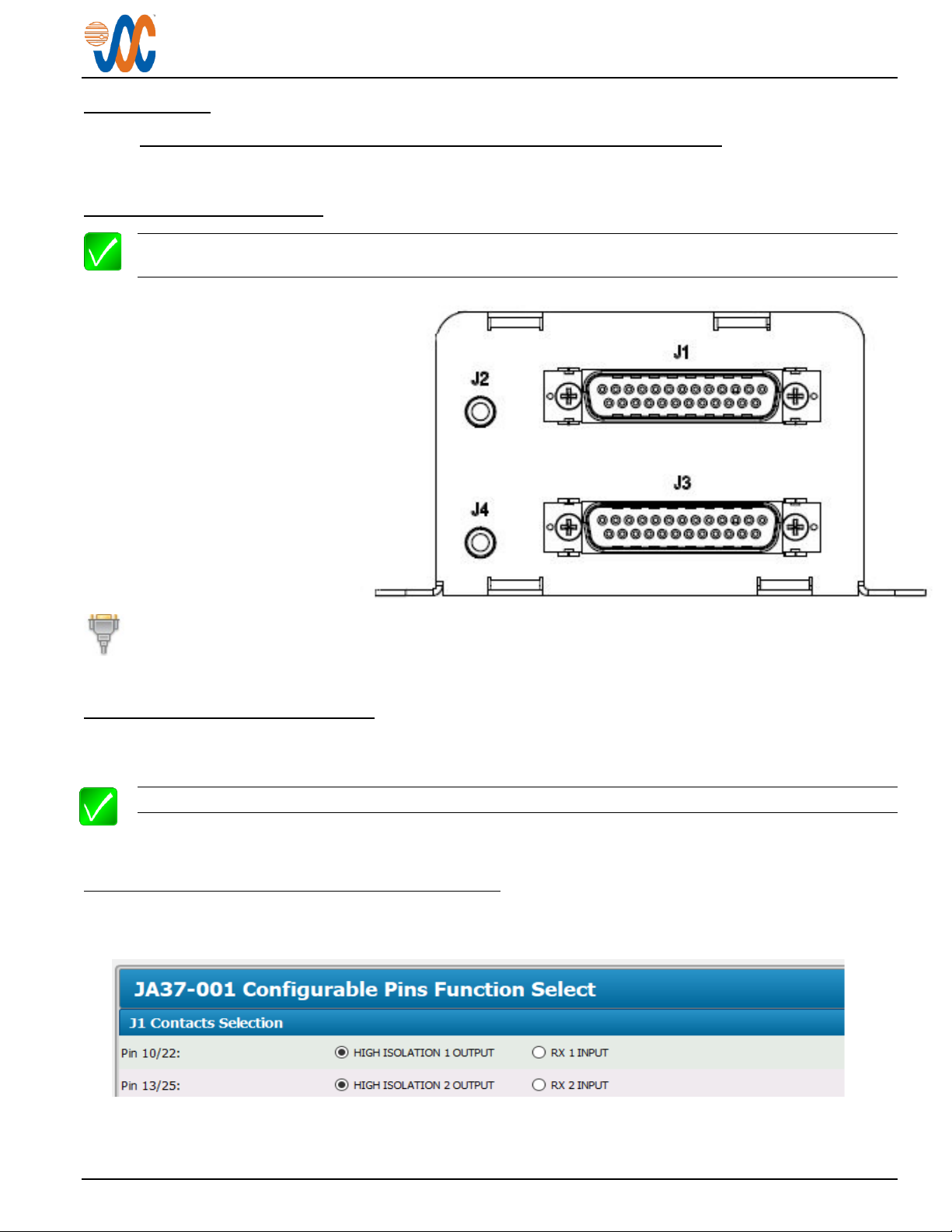
2.6.3 Configurable Settings ...................................................................................................................................... 7
2.6.4 Other Configuration Features........................................................................................................................ 11
2.7 Installation Kit ........................................................................................................................................................ 11
2.7.1 Recommended Crimp Tools ......................................................................................................................... 11
2.8 Installation Drawings ............................................................................................................................................. 11
2.8.1 Generation of Custom Drawings ................................................................................................................... 11
SECTION 3 – OPERATION.................................................................................................................................................. 12
3.1 Introduction............................................................................................................................................................ 12
3.2 Mute Switch/Button ............................................................................................................................................... 12
Appendix A - Installation Drawings...................................................................................................................................A1
A1 Introduction............................................................................................................................................................A1
A2 Installation Drawings .............................................................................................................................................A1
Appendix B - Certification Documents .............................................................................................................................B1
B1 Airworthiness Approval .........................................................................................................................................B2
B2 Instructions for Continued Airworthiness ..............................................................................................................B2

Rev A Page 1
JA37-201 Aural Message Generator - 6 Channel
SECTION 1 - DESCRIPTION
1.1 System Overview
The JA37-201 Aural Message Generator - 6 Channel is a dual channel alerting system that provides up to six different
messages.
The JA37-201 is set up on a per-installation basis using cable CAB-USB-0006, or Configuration Cable JA99-001 and
CAB-USB-0002, and downloading the system configuration settings and aural messages into non-volatile devices.
1.2 Features Overview
All internal adjustments are quickly made using the proprietary ProCS (Product Configuration Software).
Two ports are provided beside the main connectors for configuration loading.
All audio outputs are balanced.
Each message channel has two separate trigger inputs which may be active low or high dependent on the
configuration.
Each generator is provided with two isolation amplifiers.
The messages may be muted by an external switch/button.
The JA37-201 supports message lengths up to 11 seconds.
The JA37-201 is provided with a power-on Self-Test.

JA37-201 Aural Message Generator - 6 Channel
Installation and Operating Manual
Rev A Page 2
1.3 Inputs and Outputs
Refer to the JA37-201 connector maps for the mating connector designators and pin assignments for the
input and output signals.
1.3.1 Inputs
Name
Qty
Type
CONFIG DATA TO JA37-201
2
Data signal
MESSAGE TRIGGER
12
Active High/low discrete (Configurable)
MESSAGE MUTE
2
Active low discrete
POWER INPUT
2
Power supply
RX 1&2 HI/LO
4
Audio signal (Configurable)
1.3.2 Outputs
Name
Qty
Type
CONFIG DATA FROM JA37-201
2
Data signal
GROUND
4
Ground reference
PHONES HI/LO
4
Audio signal
LOW ISOLATION HI/LO
4
Audio signal
HIGH ISOLATION HI/LO
4
Audio signal (Configurable)
1.4 Specifications
1.4.1 Electrical Specifications
Power Input
Primary nominal voltage 28 Vdc
Secondary nominal voltage 14 Vdc
Maximum voltage 30.3 Vdc
Minimum voltage 11.0 Vdc
Emergency voltage 9.0 Vdc
Input current 0.5 A max per generator
1.4.1.1 Audio Performance
Rated Input Level
RX audio rated input level 7.75 Vrms ±10 %
Rated Output Level
Phones rated output power into 600 Ohm 7.75 Vrms ±10 %
Phones low isolation rated output power into 600 Ohm 3.87 Vrms ±10 %
Phones high isolation rated output power into 600 Ohm 1.94 Vrms ±10 %
Audio Frequency Response
Phones output audio frequency response ≤3 dB from 300 to 6000 Hz
Distortion Characteristics
Phones audio output distortion at rated power ≤10 %

JA37-201 Aural Message Generator - 6 Channel
Installation and Operating Manual
Rev A Page 3
Input Impedance
Receive Audio input Impedance 1000 Ω±10%
Output Impedance
Phones output Impedance 300 Ω±20 %
Phones low isolation output Impedance 1.2 kΩ±20 %
Phones high isolation output Impedance 3.0 kΩ±20 %
Output Load
Phones load 600 Ω±10 %
Input to Input Crosstalk Level
Input to Input crosstalk ≤60 dB
Audio Noise Level without Signal
Noise level below the rated output ≥60 dB
1.4.1.2 Audio Performance, Other
RX input circuitry type Transformer coupled
Phones output circuitry type Transformer coupled
1.4.1.3 Discrete Signals
Message Trigger (active low) signal level active ≤+3 Vdc
Message Trigger (active low) signal level inactive ≥+6 Vdc
Message Trigger (active high) signal level active ≥+8 Vdc
Message Trigger (active high) signal level inactive ≤+6 Vdc
Message Mute active low signal ≤+3 Vdc
1.4.2 Mechanical Specifications
Height 2.34 in [59.4 mm] max
Depth (excluding connectors) 4.42 in [112.3 mm] max
Width (including flanges) 4.52 in [114.8 mm] max
Width (without flanges) 3.52 in [89.4 mm] max
Weight 0.91 lb [0.41 kg] max
Connectors (4): J1, J3 Two 25-pin D-Sub male V5 locking
J2, J4 Two 4 pole 3.5mm jacks
Mounting 4 x 10-32 fasteners
Bonding ≤2.5 mΩ
Installation kit part number INST-JA37 (2 required)
1.4.3 Environmental Specifications
Temperature:
Operating -45 °C to +70 °C
Ground Survival -55 °C to +85 °C
1.4.4 Flammability of Materials
The JA37-201 complies with the requirements of RTCA/DO-160G Sec 26.3.3 "Flammability", by design. The JA37-
201 has an enclosure constructed of metal on all sides, and has no vent holes.

Rev A Page 4
JA37-201 Aural Message Generator - 6 Channel
SECTION 2 – INSTALLATION
2.1 Introduction
This section contains unpacking and inspection procedures, installation information, and post-installation checks.
2.2 Continued Airworthiness
Maintenance of the JA37-201 is on condition only. Scheduled inspection and/or periodic maintenance of this unit is
not required.
2.3 Unpacking and Inspecting Equipment
Unpack the equipment carefully. Check for shipping damage and report any problems to the relevant carrier. Confirm
that the Authorized Release Certificate or Certificate of Conformance is included. Complete the on-line warranty card
from the Jupiter Avionics Corporation (JAC) website - www.jupiteravionics.com/warranty
2.3.1 Warranty
This product manufactured by JAC is warranted to be free of defects in workmanship or performance for 2 years from
the date of installation by an approved JAC dealer or agency. This warranty covers the cost of all materials and labour
to repair or replace the unit, but does not include the cost of transporting the defective unit to and from JAC or its
designated warranty repair centre, or of removing and replacing the defective unit in the aircraft. This warranty does
not cover failures due to abuse, misuse, accident, or unauthorized alteration or repairs.
THIS WARRANTY IS VOID IF THE PRODUCT IS NOT INSTALLED BY AN AUTHORIZED JAC DEALER. If the on-
line warranty card is not completed, the product will be warranted from the date of manufacture.
Contact JAC for return authorization, and for any questions regarding this warranty and how it applies to your unit(s).
JAC is the final arbiter concerning warranty issues.
2.4 Installation Procedures
WARNING: Loud noise can cause hearing damage. Set the headset volume to minimum before
conducting tests, and slowly increase the volume to a comfortable listening level.
CAUTION: The power input circuitry of the unit may be damaged if the installation does not conform to the
wiring instructions in this manual.
WARNING: The messages are intended only to supplement, NOT replace, airframe messages such
as ‘low rotor RPM’, ‘engine out’ or ‘decision height alerting’. The message audio feature is intended
for use as a secondary alerting system where another device provides the primary annunciation.
2.4.1 Installation Limitations
The JA37 may be installed only by following the applicable airworthiness requirements.

JA37-201 Aural Message Generator - 6 Channel
Installation and Operating Manual
Rev A Page 5
2.4.2 Cabling and Wiring
All wire shall be selected in accordance with the original aircraft manufacturer’s maintenance instructions, or AC43.13-
1B Change 1, Paragraphs 11-76 through 11-78. Unshielded wire types shall qualify to MIL-W-22759 as specified in
AC43.13-1B Change 1, Paragraphs 11-85, 11-86, and listed in Table 11-11. For shielded wire applications, use Tefzel
MIL-C-27500 shielded wire with tag ring or equivalent (for shield terminations) to make the most compact and easily
terminated interconnect. Follow the Connector Map in Appendix A of this manual.
Allow 3” from the end of the shielded wiring to the shield termination to allow the connector hood to be easily installed.
Refer to the Interconnect drawing in Appendix A of this manual for shield termination details. Note that this unit has a
‘clamshell’ hood that is installed after the wiring is complete.
Maintain wire segregation and route wiring in accordance with the original aircraft manufacturer’s maintenance
instructions.
Unless otherwise noted, all wiring shall be a minimum of 24 AWG, except power and ground lines, which shall be a
minimum of 22 AWG. Refer to the Interconnect drawing for additional specifications. Check that the ground
connection is clean and well secured, and that it shares no path with any electrically noisy aircraft accessories such
as blowers, turn-and-bank instruments, or similar loads.
2.4.3 Mechanical Installation
The JA37-201 can be mounted in any attitude and location with adequate space and sufficient clearance for the
connector and wiring harness. It requires no direct cooling.
2.4.4 Post Installation Checks
2.4.4.1 Voltage/Resistance checks.
Do not attach this unit until the following conditions are met:
a) Check P1 and P3 pin 1for +28 Vdc or +14 Vdc relative to ground.
b) Check P1 and P3 pin 14 for continuity to ground (less than 0.5 Ω).
c) Check P1 and P3 pin 18 for continuity to ground (less than 0.5 Ω) when the relevant switch is closed.
d) Check all pins for shorts to ground or adjacent pins.
2.4.4.2 Configuration
Ensure that the JA37 contains the correct configuration settings. This may be done at the factory, on the maintenance
bench or in the aircraft before the power on checks are performed. Refer to section 2.5.1.
2.4.4.3 Power on Checks.
Power up the aircraft’s systems and confirm normal operation of all functions of the JA37.
a) Check that all configuration settings are correct.
When all performance checks are satisfied, complete the necessary regulatory documentation before releasing the
aircraft for service. Refer to Appendix B.
2.5 System Operation
Many of the System Operation parameters are configured using ProCS™ (see section 2.6).
2.5.1 Configuration Operation
The JA37-201 accepts configuration commands on the Configuration connector via the configuration cable(s) and the
configuration tool (ProCS™) – refer to section 2.6.

JA37-201 Aural Message Generator - 6 Channel
Installation and Operating Manual
Rev A Page 6
2.5.2 Message Mute Operation
The JA37-201 stops playing all messages if the MESSAGE MUTE input is activated while any MESSAGE TRIGGER
input is active (or when Power On Self-Test is occurring) and stays muted until the next message trigger event.
2.5.3 Message Operation
The JA37-201 Message 1, Message 2 and Message 3audio signal playback mode are individually selectable
between Continual and One-Shot. Message playback may also be configured for Priority operation, see section 2.5.5 –
Priority Operation.
When a message is configured as One Shot, the complete Message audio signal is routed to the phones output once
when the corresponding Message Trigger is active. When a message is configured as Continual, the Message audio
signal is routed to the phones output for the duration of the trigger input being active.
2.5.4 Power On Self-Test Operation
When the JA37-201 power is off and then POWER INPUT is applied, the three messages will play in the following
order: message 1; message 2; message 3. The Power On Self-Test messages may be muted at any time using the
MESSAGE MUTE input. See section 2.5.2.
2.5.5 Priority Operation
When Message Trigger Priority is selected (see Message Trigger Priority in section 2.6.3.1), if more than one trigger
is active, the messages will have the following priority: message 1; message 2; message 3. Note that if a higher
priority message has been triggered and is set as continual, the lower priority messages will not play until the higher
priority trigger is no longer active.
2.5.6 Non-Priority Operation
When Message Trigger Priority is not selected ('Equal Priority' in ProCS™) if more than one trigger is active, the
messages will play simultaneously (both Continual and One-Shot messages).
2.5.7 RX Audio Operation
The RX 1 and 2 Audio is level controlled and summed with the Message audio and routed to the Phones 1 and 2, Low
Isolation 1 and 2 outputs.
2.6 Adjustments and Configuration using ProCS™
All the JA37-201 internal adjustments are set from the Product Configuration Software ProCS™. Configuration data is
sent to the JA37-201 via the configuration connector using the Configuration Cables and a computer running the
ProCS™ software. For configuration requirements, see section 2.5.1.
For full information on the configuration process, and for installation of ProCS™ on your computer, refer to the
ProCS™ manual on the Jupiter Avionics website - www.jupiteravionics.com/productsoftware.
2.6.1 Configuration Cabling Requirements
To configure the JA37-201, it is necessary to load the Product Configuration Software ProCS™ onto a Windows-
based computer as described in the ProCS™ manual.
The cables required to configure the JA37-201 are not included with the unit.
Cabling option 1:
Quantity Description JAC Part #
1 USB A to RS232 9-Pin Cable CAB-USB-0002
1 Configuration Cable JA99-001

JA37-201 Aural Message Generator - 6 Channel
Installation and Operating Manual
Rev A Page 7
Cabling option 2:
Quantity Description JAC Part #
1 USB A Male to RS232 3.5mm Plug CAB-USB-0006
2.6.2 ProCS™ Setup
Note: The JA37-201 consists of two JA37-001 units installed in a single box, each with a configuration jack.
Each section of the unit is configured separately using the JA37-001 ProCS menu.
The upper section of the
JA37-201 (connector J1) is
configured via configuration
jack J2.
The lower section of the
JA37-201 (connector J3) is
configured via configuration
jack J4.
The ProCS™ JA37-001 menu item 'ProCS Setup' provides Setup drawings showing the cabling arrangement
for connecting each section of the JA37-201 to a computer running the ProCS™.
2.6.3 Configurable Settings
A standard unit is shipped from the factory with all internal adjustments configured to the default levels. At installation,
it may be desirable to change some of these settings to suit the local operating environment.
Note: To properly configure the JA37-201, power must be applied to each unit.
Within ProCS™, the JA37-001 configurable settings are grouped together into the following sections:
2.6.3.1 JA37-201 Configurable Pins Function Select
Several of the connector pins can be configured to meet the requirements of specific installations. Refer to the
JA37-201 Interconnect.Other configuration options may be unavailable, depending upon the selections made.

JA37-201 Aural Message Generator - 6 Channel
Installation and Operating Manual
Rev A Page 8
The message trigger activation can be selected as Active Hi, or Active Lo.
If the 'Message Trigger Priority' box is checked, the signal Priority will be shown.
The message Playback may be selected as 'Continual' or 'One-Shot' for each message (1 through 3).

JA37-201 Aural Message Generator - 6 Channel
Installation and Operating Manual
Rev A Page 9
2.6.3.2 JA37-201 Messages
Audio Files
The JA37-201 is loaded with standard audio signals for each of the three messages in each unit, but the audio
files window allows these signals to be replaced with other recordings during the configuration process.
Selecting 'Open…' will open to the Jac>ProCS folders on the attached computer, but will also allow browsing of
any directory accessible from the computer, and any suitable uploaded WAV file.
If a new audio file is selected, it may be played using the arrow to the right of the Message line. See 'Saving new
Audio files' below.
Phones 1 and Phones 2 Message Levels
For each of the Phones Outputs, the levels for the Messages can be adjusted from -42.5 to 0 dB. (default -20 dB)
Browse for audio files
Play selected audio file

JA37-201 Aural Message Generator - 6 Channel
Installation and Operating Manual
Rev A Page 10
Saving new Audio Files.
Note: This pane will not have the full content
shown here if no JA37-201 is connected.
When suitable alert messages are listed in the
'Audio Files' section, they are uploaded to the JA37
by selecting 'Program' from the main ProCS menu,
and clicking on
'Write JA37-001 Messages…'.
The window 'Select Messages to Write' (see below)
will open, allowing the selected audio file message
to be uploaded to the JA37-201. ProCS will
automatically convert any WAV file to the required
audio sample rate for the JA37-201.
A selection of suitable WAV files can be found on
the JAC website:
Products>Software>Wave File Messages
www.jupiteravionics.com/productsoftware
The 'Select Messages to Write'
window is shown. Similar windows
will open for the 'Read' and 'Erase'
selections. The desired message
is chosen using the check box to
the right of the message number,
or by clicking on the 'Select All'
button.
2.6.3.3 JA37-201 RX Audio Levels
When RX Input is selected from the Configurable Pins Function Select section (section 2.6.3.1) the Phones 1 and
Phones 2 RX AUDIO levels may be may be selected from 1 to 8 Vrms (default 7.8 Vrms).

JA37-201 Aural Message Generator - 6 Channel
Installation and Operating Manual
Rev A Page 11
2.6.4 Other Configuration Features
In the JA37-201 Product Information Window, the model number, serial number and check sum of the JA37-201 audio
panel can be viewed.
2.7 Installation Kit
Two INST-JA37 kits are required to install this unit, and are not included with the unit.
Each installation kit (Part # INST-JA37) consists of the following:
Quantity Description JAC Part #
1 TAG ring 3/8" ID CON-5500-0375
1 D-Sub 25-pin connector, hood and 25 crimp pins CON-3420-0025
1 3/4" Inside Diameter, Heat Shrink Tube WIR-HTSK-0750
2.7.1 Recommended Crimp Tools
Standard D-Sub Crimp Tool Chart
Tool Type
Hand crimping tool
Positioner
Insertion/extractor tool
POSITRONIC
9507-0-0-0
9502-5-0-0
4711-2-0-0
DANIELS
AFM 8
K13-1
91067-2
MIL-SPEC
M22520/2-01
M22520/2-08
M81969/1-02
2.8 Installation Drawings
The drawings and documents required for Installation can be found in Appendix A of this manual.
2.8.1 Generation of Custom Drawings
The interconnects and connector maps in Appendix A of this manual are generic drawings based on the standard
version of the JA37-201. However, if a unit has been configured using JAC’s ProCS™ software, the software can be
used to generate fully customized interconnects and connector maps for use by the installer.

Rev A Page 12
JA37-201 Aural Message Generator - 6 Channel
SECTION 3 – OPERATION
3.1 Introduction
This section contains the operating instructions for the JA37-201.
Note: The JA37-201 has no integrated operator controls. However, a remote-mounted mute switch or button
may be installed, which affects the operation of the unit.
3.2 Mute Switch/Button
If the JA37-201 is playing Alert messages (either because an alert input is active or when Power On Self-Test is
occurring), momentary activation of the remote Message Mute switch or button stops all messages from playing until
the next message is triggered.

Rev A Page A1
JA37-201 Aural Message Generator - 6 Channel
Installation and Operating Manual
Appendix A - Installation Drawings
A1 Introduction
The drawings necessary for installation and troubleshooting of the JA37-201 Aural Message Generator - 6 Channel
are in this Appendix, as listed below.
Note: A fully customized set of Connector Maps and Interconnects can be created using the ProCS software.
Refer to the ProCS™ manual for further information.
A2 Installation Drawings
DOCUMENT Rev
JA37-201 Connector Map A
JA37-201 Interconnect A
JA37-201 Mechanical Installation A

JUPITER AVIONICS TEMPLATE AUTOCAD PORTRAIT SIZEA REV B.DWT
TITLE
APPROVED
PREPARED
CHECKED
L00N3
NCAGE CODE PART NO. SHEET
DOC NO.
CONFIDENTIAL & PROPRIETARY
TO JUPITER AVIONICS CORP.
Aural Message Generator
P1 & P3 Connector Map
JA37-201 1/2
JA37-201 Connector Map Rev A.dwg
TAT
1 2 3 4 5
14 15 16 17
POWER INPUT
MESSAGE 1 TRIGGER A
MESSAGE 1 TRIGGER B
MESSAGE 2 TRIGGER A
MESSAGE 2 TRIGGER B
GROUND
P1 & P3
25 PIN FEMALE DMIN
MATING CONNECTOR
VIEW IS FROM REAR OF MATING CONNECTOR
6 7 8 9 10 11 12 13
18 19 20 21 22 23 24 25
MESSAGE 3 TRIGGER A
MESSAGE 3 TRIGGER B
PHONES 1 HI
LOW ISOLATION 1 HI
HIGH ISOLATION 1 HI / RX 1 HI
PHONES 2 HI
LOW ISOLATION 2 HI
HIGH ISOLATION 2 HI / RX 2 HI
POWER GROUND
GROUND
GROUND
MESSAGE MUTE
GROUND
PHONES 1 LO
LOW ISOLATION 1 LO
HIGH ISOLATION 1 LO / RX 1 LO
PHONES 2 LO
LOW ISOLATION 2 LO
HIGH ISOLATION 2 LO / RX 2 LO
1Configurable Contact
1 1
1 1
JAC
SDB
05-26-20
JAC
KDV
05-26-20

P2 & P4
4 POLE MALE 3.5MM PLUG
TIP: TX DATA
1ST RING: RX DATA
2ND RING: GROUND
3RD RING: MODE SELECT
ACCEPTS THE FOLLOWING PLUG FORMATS
JA99-001 CONFIGURATION CABLE
MATING PLUG NAMES JA37 SIGNAL NAMES
CONFIG DATA TO JA37
CONFIG DATA FROM JA37
GROUND
MODE SELECT
CONFIGURATION CONNECTOR
JUPITER AVIONICS TEMPLATE AUTOCAD PORTRAIT SIZEA REV B.DWT
TITLE
APPROVED
PREPARED
CHECKED
L00N3
NCAGE CODE PART NO. SHEET
DOC NO.
CONFIDENTIAL & PROPRIETARY
TO JUPITER AVIONICS CORP.
Aural Message Generator
P2 & P4 Connector Map
JA37-201 2/2
JA37-201 Connector Map Rev A.dwg
TAT
CAB-USB-0006 or
JAC
SDB
05-26-20
JAC
KDV
05-26-20

JUPITER AVIONICS TEMPLATE AUTOCAD PORTRAIT SIZEA REV B.DWT
TITLE
APPROVED
PREPARED
CHECKED
L00N3
NCAGE CODE PART NO. SHEET
DOC NO.
CONFIDENTIAL & PROPRIETARY
TO JUPITER AVIONICS CORP.
Aural Message Generator
JA37-201 1/4
JA37-201 Interconnect Rev A.dwg
TAT
JA37-201 INTERCONNECT WIRING NOTES
NOTES
ALL WIRE SIZE SHOULD BE 24 AWG MIN UNLESS OTHERWISE SPECIFIED. UNSHIELDED
WIRE SHOULD BE SELECTED PER FAA AC43.13-1B CHANGE 1 PARA 11-76 TO 11-78. WIRE
TYPES SHOULD BE IN ACCORDANCE WITH MIL-W-22759 AS DESCRIBED IN FAA AC43.13-1B
CHANGE 1 PARA 11-85 AND 11-86 AND LISTED IN TABLE 11-11 OR 11-12. ALL SHIELDED
CABLE SHOULD BE IN ACCORDANCE WITH MIL-DTL-27500 (REVISION H OR LATER).
USE FOR SECOND SOURCE INPUT.
USE AS GROUND REFRENCE FOR SWITCH CLOSURE WHEN TRIGGERS CONFIGURED AS
ACTIVE LOW.
PROVIDES 50% REDUCTION IN AUDIO POWER AND LESS LOADING.
PROVIDES 67% REDUCTION IN AUDIO POWER AND THE LEAST LOADING.
EXAMPLES OF MESSAGE TRIGGERS.
CONNECTION TO AIRFRAME GROUND SHOULD BE MADE WITH 20 AWG WIRE. LENGTH NOT
TO EXCEED 3 FT (0.91 M).
CONNECTOR PIN HAS MORE THAN ONE FUNCTION. SEE THE OPTIONS SECTION OF THIS
DRAWING FOR ALTERNATIVE INTERCONNECT WIRING.
CABLE SHIELDS AT THE JA37 CONNECTOR END SHOULD BE TERMINATED TO AIRFRAME
GROUND USING THE TAG RING SUPPLIED IN THE INSTALLATION KIT OR EQUIVALENT.
USE FOR MUTING OR ACKNOWLEDGING MESSAGE.
2
1.
3
4
5
6
7
8
9
10
JAC
SDB
05-26-20
JAC
KDV
05-26-20

PHONES 1 HI
PHONES 1 LO 8
20
JA37-201 J3 P3
25 PIN FEMALE DMIN
MATING CONNECTOR
JUPITER AVIONICS TEMPLATE AUTOCAD PORTRAIT SIZEA REV B.DWT
TITLE
APPROVED
PREPARED
CHECKED
L00N3
NCAGE CODE PART NO. SHEET
DOC NO.
Aural Message Generator
Power and Audio Interconnect
JA37-201 2/4
JA37-201 Interconnect Rev A.dwg
TAT
POWER INPUT 1
POWER GROUND 14
MESSAGE MUTE 18
LOW ISOLATION 1 HI 9
LOW ISOLATION 1 LO 21
HIGH ISOLATION 1 HI 10
HIGH ISOLATION 1 LO 22
11
23
12
24
13
25
4
5
4
9
9
22 AWG
PHONES 2 HI
PHONES 2 LO
LOW ISOLATION 2 HI
LOW ISOLATION 2 LO
HIGH ISOLATION 2 HI
HIGH ISOLATION 2 LO
20 AWG
10
5
PHONES 1 HI
PHONES 1 LO DIRECT AUDIO INPUT
8
20
JA37-201 J1 P1
25 PIN FEMALE DMIN
MATING CONNECTOR
AIRFRAME GROUND
+14 TO +28 VDC POWER
1A
POWER INPUT 1
POWER GROUND 14
MESSAGE MUTE 18
LOW ISOLATION 1 HI 9
LOW ISOLATION 1 LO 21
RX 1 HI 10
RX 1 LO 22
11
23
12
24
13
25
4
4
7
AUDIO CONTROLLER
TO PILOT'S
DIRECT AUDIO INPUT
AUDIO CONTROLLER
TO COPILOT'S
9 7
9 7
22 AWG
PHONES 2 HI
PHONES 2 LO
LOW ISOLATION 2 HI
LOW ISOLATION 2 LO
RX 2 HI
RX 2 LO
20 AWG
10
P/O J1 P/O P1
MESSAGE MUTE
JAC
SDB
05-26-20
JAC
KDV
05-26-20
Table of contents
Popular Inverter manuals by other brands

Generac Power Systems
Generac Power Systems MMG120 Specifications

SMA
SMA SUNNY BOY STORAGE 5.0 Quick reference guide

Briggs & Stratton
Briggs & Stratton PowerSmart P2000 Quick setup guide

Turbo Energy
Turbo Energy SunBox H instruction manual

SEW-Eurodrive
SEW-Eurodrive MOVIDRIVE system operating instructions

ProVista Technology
ProVista Technology TSW600 Basic operating manual