Jura Claris Operating instructions

Installation and Operation Guide
CLARIS filter cartridge family

2
1
Short installation guide
Bypass level
Do not use with water that is microbiologically unsafe or of unknown quality without adequate disinfection before or after the system.
Bestellinformation / Order information
Information sur la commande / Informazioni sull‘ordine S M L XL
CLARIS Filterkopf li/re – 3/8“
CLARIS Filterhead le/ri - 3/8“
Tête de filtration CLARIS gche/dte - 3/8“
Testa del filtro CLARIS sx/dx - 3/8“
69538 69538 69538 69538
Wasserfilter CLARIS
Waterfilter CLARIS
Filtre à eau CLARIS
Filtro dell’acqua CLARIS
69534 69535 69536 69537
S/M min. > 5 l (1.5 US gal)
L/XL min. > 10 l (3.0 US gal)
3
12
69562 | 70.900.854/V1 JURA Elektroapparate AG, Kaffeeweltstrasse 10, CH-4626 Niederbuchsiten, Tel. +41 389 81 81, www.jura.com

A 1
Overview of components
A 3 A 4
A 2
4
5
69
1
7
8
2
3
8
watertechnology
Definitions of terms:
1 Filter head
2 Mounting bracket
3 Filter cartridge
4 Bypass adjustment cap
5 Bypass levels
6 Flush/pressure release valve
7 Inlet
8 End position mark
9 Outlet

1. General information
The filter system consists of the following parts (see page 3):
• Filter head
• Mounting bracket
• Filter cartridge
The filter cartridges are available in 4 sizes (S/M/L/XL).
The corresponding filter head and mounting bracket fits to all cartridge sizes.
2. Special instructions
2.1 Staff
The installation and maintenance of the filter systems may only be carried out by trained and authorised personnel.
2.2 Disclaimer
Information contained in this document is believed to be accurate at the time of publication,
but does not constitute a contractual offer. The right is reserved to alter specifications without prior notice. Illustrations
and tabulated data are for guidance only. JURA does not assume liability for any damages, including subsequent
damages, that may result from incorrect installation or usage of the products.
JURA does not assume liability for damage caused by using parts from other manufacturers.
2.3 Safety Information
• Only cold water of potable water quality may be used to feed the system.
• All components must be stored dry within a temperature limit of -15° to 45° C (5 °F to 113 °F)
• Water of unsafe or unknown microbiological quality may not be used.
• The system must be sited in a frost-proof place and be protected from direct sunlight.
• The system must not come into contact with chemicals, solvents or other vapours.
• Before commissioning the filter system, the fed appliance must be free of lime.
• The filter cartridge must not be opened or damaged.
• The filter cartridge should be replaced if not used for very long periods.
• After 5 years of use (latest 6 years after production date) the filter head and wall mounting bracket must be
replaced (this also applies to hoses and gaskets) – please check the date on the production stamp.
• After a longer downtime or maintenance works rinse the system thoroughly – see table for flush volume.
Filter system Flush volume
after 1 week of stagnation
Flush volume
after 4 weeks of stagnation
CLARIS S 2 liters (0.5 US gal) 10 liters (3 US gal)
CLARIS M 3 liters (1.0 US gal) 15 liters (4 US gal)
CLARIS L 5 liters (1.5 US gal) 25 liters (7 US gal)
CLARIS XL 8 liters (2.0 US gal) 40 liters (11 US gal)
3. Applications
The CLARIS filter systems are typically used to feed the following appliances:
• Coffee and espresso machines
• Drinks vending machines
• Combi Steamers and Self-Cooking Systems
• Steam Cookers and Ovens
The systems can be operated horizontally or vertically, depending on the space available.
4. Function
The CLARIS filter systems use ion-selective filter medium to reduce the carbonate hardness of potable water.
The DuoBlend®bypass valve in the filter head can be used to precisely adjust the carbonate hardness of the filtered
water and to adapt it to the application.
The filter material also reduces heavy metal ions like lead, copper and cadmium.
The integrated active carbon block reduces undesirable cloudiness, organic impurities, odour and taste and chlorine
residue from the filtrate and bypass water.

5. Installation and Bypass level adjustment
5.1 Safety-related installation instructions
• Water pressure at the filter system inlet must not exceed 8 bar (116 psi). A pressure reducer must be installed on
the water supply side of the filter system if the inlet pressure exceeds 8 bar (116 psi).
• A shut-off valve must be installed upstream of the filter system.
• If a water softener is installed upstream, use filter only for tapwater > 6° dH / 10,7° FH / 107 PPM total hardness.
• No copper pipes, galvanised or nickel-coated pipes or intermediate parts may be installed between the filter
system and the point of dispense.
• All components must be installed according to country-specific guidelines. Check for compliance with state
and local laws and regulations.
• DIN 1988 should be noted for installing and operating the system.
• We recommend only using genuine accessory hoses for the CLARIS system because these have a longer thread.
• If the cartridge is removed from the filter head without being replaced by a new one, the water supply to the
filter head must be shut off.
• Do not connect any devices to the flush valve and/or flush hose.
5.2 Initial installation
At first identify a suitable place to install the filter system. Note the information provided in chapter 2.
Before you start installing the system, shut off the water supply and disconnect the equipment from the power supply.
Before installation check the filter system and the accessories for any damage – particular attention must be paid
when inspecting the o-rings and gaskets.
After storage below 0° C (32 °F) the filter cartridge must be stored at the ambient temperature of the installation
location for at least 24 hours.
NOTE: The hoses for the supply and discharge line are not supplied as standard but can be ordered as accessories.
Atest kit for determining the water hardness is also available as an accessory. You will find more details in section 9.
5.2.1 Installation of filter head / Mounting bracket / Filter cartridge
The system can be operated either freestanding or wall mounted in a vertical or horizontal position.
1) If mounting vertically to a wall, securely connect the mounting bracket to the wall using suitable Ø 5mm screws
(#10-12 x ¾” tap screws) (Not included).
2) Install the hoses for the water inlet and outlet to the filter head and respect the following:
• Note the direction of flow – indicated by arrows on the filter head!
• Max. Torque 10 Nm (88 lbf in) on 3/8” threaded connections when using genuine CLARIS accessory hoses.
• Filter heads with threaded connections must only use connecting hoses with flat gaskets. Don’t use hoses or
adapter with conical screw connections, they damage the connectors on the filter head and invalidate any
warranty claims.
• Only use adaptor nipples of a matching connection type and length to the head connectors, adaptor nipples
must not contact and rest axially on the head. Adaptors of improper design can damage the connections of the
filter head and invalidate any warranty claims.
• Open the flush/pressure release valve (see page 3, A 4) and direct the flush hose into a suitable container
(e.g. bucket) or to the drain.
• Turn on the water supply.
3) Insert the filter cartridge into the filter head and turn it clockwise until the end position is reached. This vents the
system and flushes the filter cartridge (filter size S/M > 5 l / 1.5 US gal; filter size L/XL > 10 l / 3.0 US gal). You
can check the correct end position using the matching marks on the mounting bracket and filter cartridge
(see page 3, position 8).
4) Close the flush/pressure release valve (see page 3, A 3) - the system is now ready for use.
5) After installing the system and inserting the filter cartridge, check all components for leaks, water must not escape
from any point.
5.2.2 Replacing a filter cartridge
1) Slowly unscrew the used cartridge by turning counter-clockwise. This will unlock it from the filter head and
enable it to be removed. During this process, incoming tapwater supply and outgoing filtered water valves in the
filter head shut-off automaticaly.
The system will expand and a small amount of expansion water may escape from the flush hose due to peaks
in pressure.
Please keep this in mind and place a suitable container underneath the flush hose.
2) Open the flush/pressure release valve (see page 3, A 4) and lead the rinsing hose into a suitable
container (e.g. bucket) or to the drain.
3) Remove the new filter cartridge from its packaging and check for any damage.
4) Insert the filter cartridge into the filter head and turn the cartridge clockwise until its end position is reached
(see page 3, position 8). The flow in the filter head is reopened and the system vented and flushed via the
flush/pressure release valve (cartridge size S/M > 5 l / 1.5 US gal; cartridge size L/XL > 10 l / 3.0 US gal).
5) Close the flush/pressure release valve (see page 3, A 3) - the system is now ready for use.
6) After replacing the filter cartridge, check all components for seal integrity, water must not escape from any point.

NOTE: The flush water will be milky or cloudy at first. This is due to the dispersing air and will clear up
quickly. Now check that the cartridge position is correct by ensuring the marks on the wall mounting bracket and filter
cartridge are aligned (see page 3, position 8). When inserting the cartridge, check the position of the cartridge label.
This should face forwards once in the end position so that all of the necessary information is visible.
5.2.3 Determining the carbonate hardness
Use the corresponding test kit to determine the carbonate hardness in the water supply. A test kit for determining
water hardness is available as an accessory.
In order to compensate for fluctuations in the quality of feed water and measuring errors of the test kit we
recommend to add 2° KH / 2° Clarke / 30 PPM / 3° FH to the value determined.
Use this value to determine the recommended bypass level setting according to chapter 5.2.4 and for the
determination of the filter capacity according to chapter 5.2.5.
5.2.4 Bypass level adjustment
NOTE: Adjust the bypass level only with the cartridge assembled to the head.
To adjust the bypass level for your application, lift up the bypass adjustment cap (see page 3, position 4) and set
the bypass level specified in the table in chapter 10. Then push down the bypass adjustment cap back onto the filter
head to lock the cap in position.
5.2.5 Determining the filter capacity
Based on the carbonate hardness level of the water supply and your application, use the tables in chapter 10 to
identify the recommended bypass setting and the resultant filter cartridge capacity.
Please mark the installation and replacement dates in the corresponding boxes on the cartridge label.
6. Settings / Capacities
The unique DuoBlend®bypass valve technology enables precise adjustment of carbonate hardness in the filtered
water. It is possible to adjust the bypass level to best suit the appliance type, i.e. hot drinks with steam (COFFEE-
ESPRESSO), without steam (VENDING), as well as for Combi Steamers, Self - Cooking Systems, Steam Cookers
and Ovens whether using direct injection or boiler systems, in order to maximise cartridge capacity taking into
consideration local water quality.
7. Service / Maintenance
Reliable system function can only be achieved if the filter cartridge is replaced on a regular basis.
The replacement cycle depends on the carbonate hardness of the water supply, the application and the
bypass level.
We would recommend replacing the filter cartridge after 6 months and no later than 12 months depending on usage.
The operator undertakes to check the system for leaks every day.
When the filter cartridge is replaced, all parts must be checked for impurities and damage. Damaged parts must be
replaced and impurities remedied.

12
8. Technical data
Dimensions S M L XL
Height, filter system [mm] 365 475 410 525
Height, filter cartridge [mm] 315 425 360 475
Diameter of filter cartridges [mm] 95 95 136 136
Min. distance from ground [mm] 40 40 40 40
Weight [kg] 1.3 1.8 3.2 4.3
Operating data
Max. system pressure 2 - 8 bar (29 - 116 psi)
Water temperature / ambient temperature 4° - 30° C (39 °F - 86 °F)
9. Order information
Description S M L XL
Waterfilter CLARIS 69534 69535 69536 69537
CLARIS Filterhead le/ri - 3/8” 69538
CLARIS Flow Sensor 3/8“ x 3/8“ 69563
Test kit for determining carbonate hardness 69151D
CLARIS Connection Hose 3/8” x 3/8” 69539

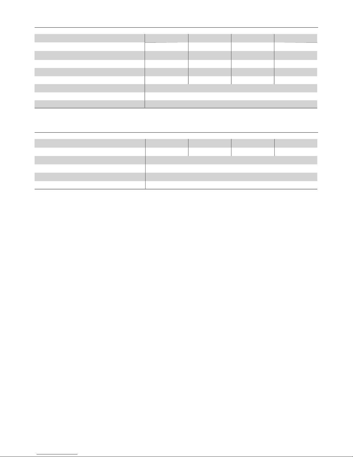
Coffee and Vending machines
Combi Steamers / Self-Cooking Systems / Steam Cookers / Ovens
Direct Injection
°KH °Clarke
(GB) PPM °FH
By-
pass-
levels
capacity in liters
SMLXL
< 6 8 107 11 0 1'500 2'500 4'660 6'670
7 9 125 13 0 1'290 2'140 4'000 5'710
8 10 143 14 0 1'130 1'880 3'500 5'000
9 11 161 16 0 1'000 1'670 3'110 4'440
10 13 179 18 0 900 1'500 2'800 4'000
11 14 196 20 0 820 1'360 2'550 3'640
12 15 214 21 0 750 1'250 2'330 3'330
13 16 232 23 0 690 1'150 2'150 3'080
14 18 250 25 0 640 1'070 2'000 2'860
15 19 268 27 0 600 1'000 1'870 2'670
16 20 286 29 0 560 940 1'750 2'500
17 21 304 30 0 530 880 1'650 2'350
19 24 339 34 0 470 790 1'470 2'100
21 26 375 38 0 430 710 1'330 1'900
23 29 411 41 0 390 650 1'220 1'740
26 33 464 46 0 350 580 1'070 1'540
29 36 518 52 0 310 520 960 1'380
33 41 589 59 0 270 450 850 1'210
38 48 679 68 0 240 390 730 1'050
Capacities are intended as guidelines and can vary according the machine typ.
Please contact us for recommendations.
Boiler System
°KH °Clarke
(GB) PPM °FH
By-
pass-
levels
capacity in liters
SM L XL
< 6 8 107 11 3 2'140 3'570 6'670 9'520
7 9 125 13 3 1'840 3'060 5'710 8'160
8 10 143 14 2 1'410 2'340 4'370 6'250
9 11 161 16 2 1'250 2'080 3'890 5'550
10 13 179 18 2 1'130 1'880 3'500 5'000
11 14 196 20 2 1'020 1'700 3'180 4'550
12 15 214 21 2 940 1'560 2'920 4'170
13 16 232 23 2 870 1'440 2'690 3'850
14 18 250 25 2 800 1'340 2'500 3'570
15 19 268 27 2 750 1'250 2'330 3'330
16 20 286 29 2 700 1'170 2'190 3'120
17 21 304 30 2 660 1'100 2'060 2'940
19 24 339 34 2 590 990 1'840 2'630
21 26 375 38 1 480 790 1'480 2'120
23 29 411 41 1 430 720 1'350 1'930
26 33 464 46 1 380 640 1'200 1'710
29 36 518 52 1 340 570 1'070 1'530
33 41 589 59 1 300 510 940 1'340
38 48 679 68 1 260 440 820 1'170
Capacities are intended as guidelines and can vary according the machine typ.
Please contact us for recommendations.
Coffee-Espresso
°KH °Clarke
(GB) PPM °FH
By-
pass-
levels
capacity in liters
SML XL
< 6 8 107 11 5 3'000 5'000 9'200 13'200
7 9 125 13 5 2'570 4'280 7'890 11'310
8 10 143 14 4 1'870 3'120 5'750 8'250
9 11 161 16 4 1'670 2'780 5'110 7'330
10 13 179 18 4 1'500 2'500 4'600 6'600
11 14 196 20 4 1'360 2'270 4'180 6'000
12 15 214 21 3 1'070 1'790 3'290 4'710
13 16 232 23 3 990 1'650 3'030 4'350
14 18 250 25 3 920 1'530 2'820 4'040
15 19 268 27 3 860 1'430 2'630 3'770
16 20 286 29 3 800 1'340 2'470 3'540
17 21 304 30 3 760 1'260 2'320 3'330
19 24 339 34 3 680 1'130 2'070 2'980
21 26 375 38 2 540 890 1'640 2'360
23 29 411 41 2 490 810 1'500 2'150
26 33 464 46 2 430 720 1'330 1'900
29 36 518 52 2 390 650 1'190 1'710
33 41 589 59 2 340 570 1'040 1'500
38 48 679 68 2 300 490 910 1'300
The COFFEE-ESPRESSO application describes the production of hot drinks with
steam operation. The stated capacities are intended as guidelines for single cup
dispense. The capacities may vary according to dispensed volume and machine
type. Please contact us for recommendations.
Vending
°KH °Clarke
(GB) PPM °FH
By-
pass-
levels
capacity in liters
SM L XL
< 6 8 107 11 6 3'540 6'250 11'670 16'670
7 9 125 13 6 3'040 5'360 10'000 14'280
8 10 143 14 5 2'120 3'750 7'000 10'000
9 11 161 16 5 1'890 3'330 6'220 8'890
10 13 179 18 5 1'700 3'000 5'600 8'000
11 14 196 20 5 1'550 2'730 5'090 7'270
12 15 214 21 4 1'180 2'080 3'890 5'550
13 16 232 23 4 1'090 1'920 3'590 5'130
14 18 250 25 4 1'010 1'790 3'330 4'760
15 19 268 27 4 940 1'670 3'110 4'440
16 20 286 29 4 880 1'560 2'920 4'170
17 21 304 30 4 830 1'470 2'750 3'920
19 24 339 34 4 750 1'320 2'460 3'510
21 26 375 38 3 580 1'020 1'900 2'720
23 29 411 41 3 530 930 1'740 2'480
26 33 464 46 3 470 820 1'540 2'200
29 36 518 52 3 420 740 1'380 1'970
33 41 589 59 3 370 650 1'210 1'730
38 48 679 68 3 320 560 1'050 1'310
The VENDING application describes the production of hot drinks without steam
operation. The stated capacities are intended as guidelines for single cup
dispense. The capacities may vary according to dispensed volume and machine
type. Please contact us for recommendations.
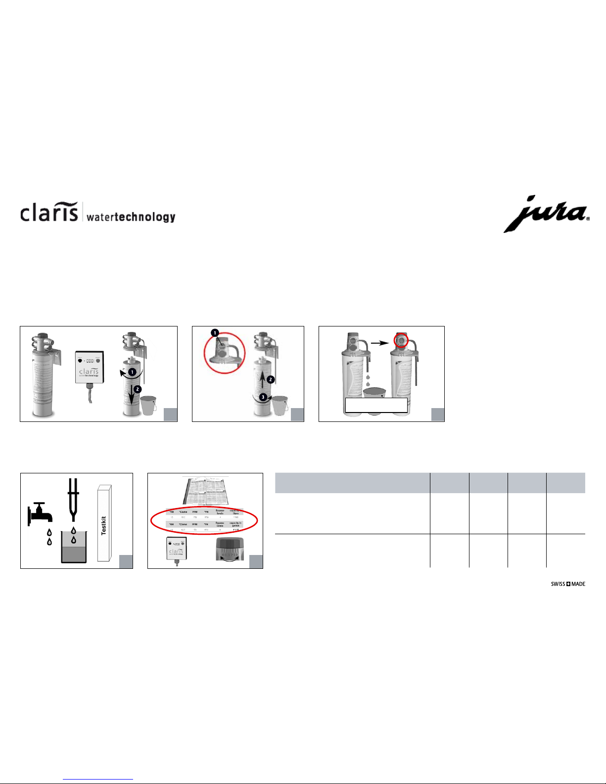
10a. Settings and Capacities in liters

46
Notes

47
Notes

69560 | 70.900.863/V1
JURA Elektroapparate AG
Kaffeeweltstraße 10
CH-4626 Niederbuchsiten
www.jura.com
Table of contents
Other Jura Water Filtration System manuals
Popular Water Filtration System manuals by other brands

My Water Filter
My Water Filter MWF BIG BLUE WHOLE HOUSE WATER FILTRATION... Installation Instructions and Product Care

Oase
Oase Eco Control operating instructions

Spectra
Spectra VENTURA TROPICAL 200 DELUXE owner's manual

AAF
AAF FabriPulse BinVent Installation, operation and maintenance manual

ZeroWater
ZeroWater ZJ-004S owner's manual

Tetra
Tetra FilterJet 400 instruction manual