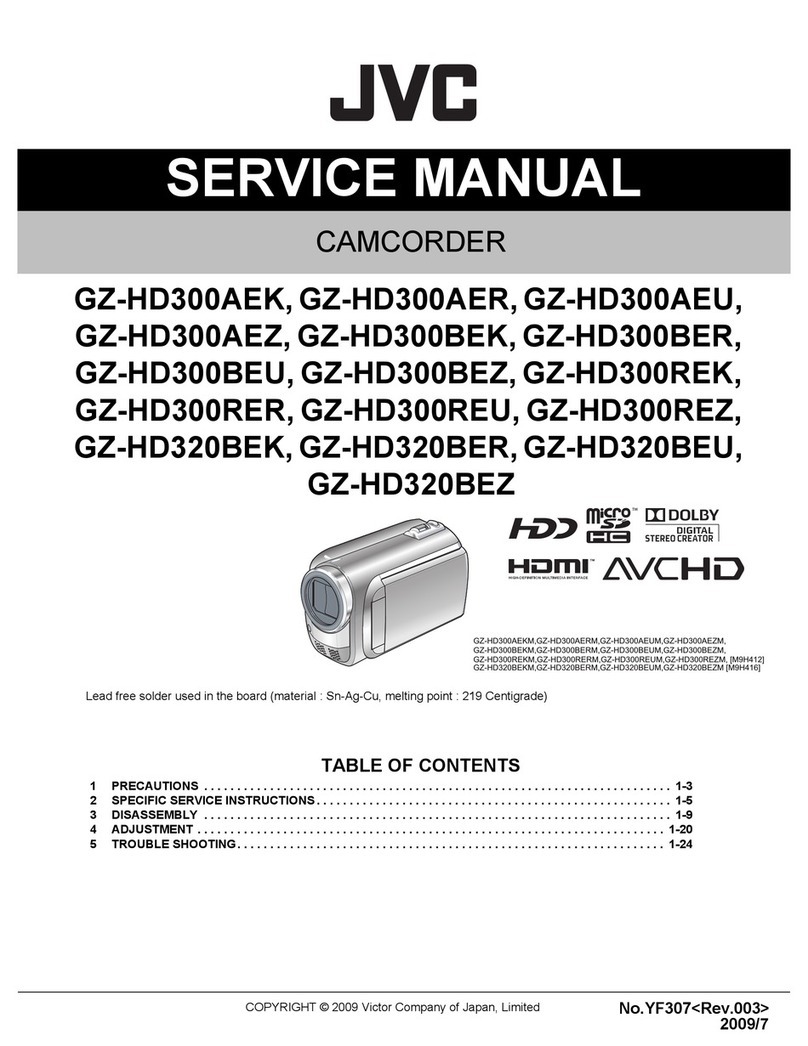
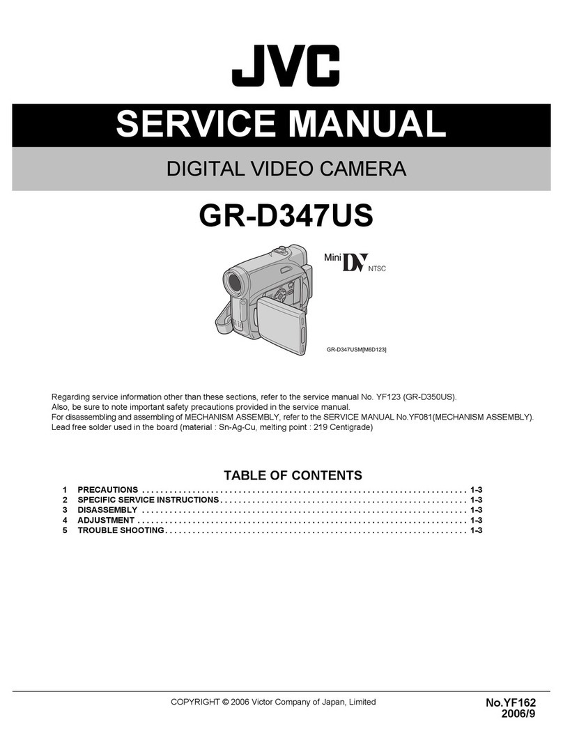
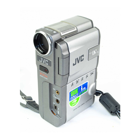
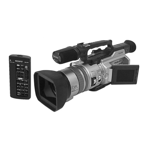
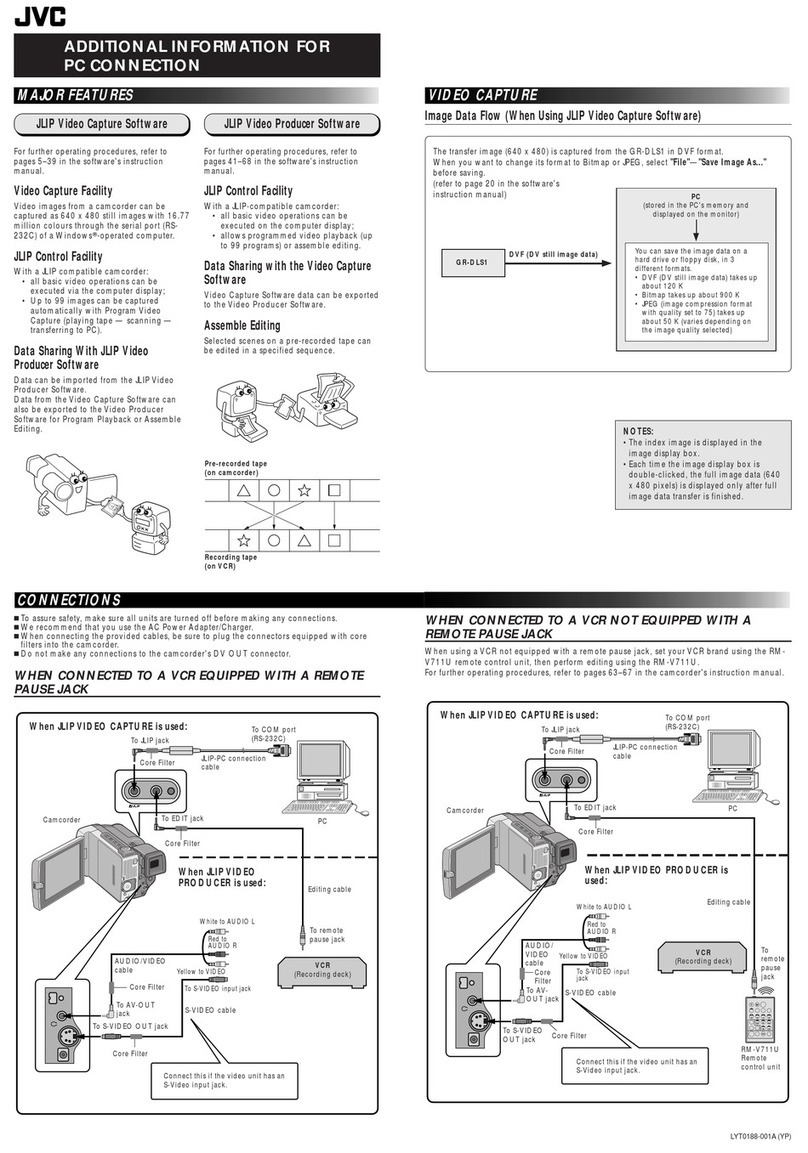
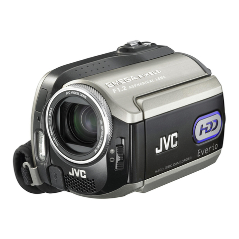
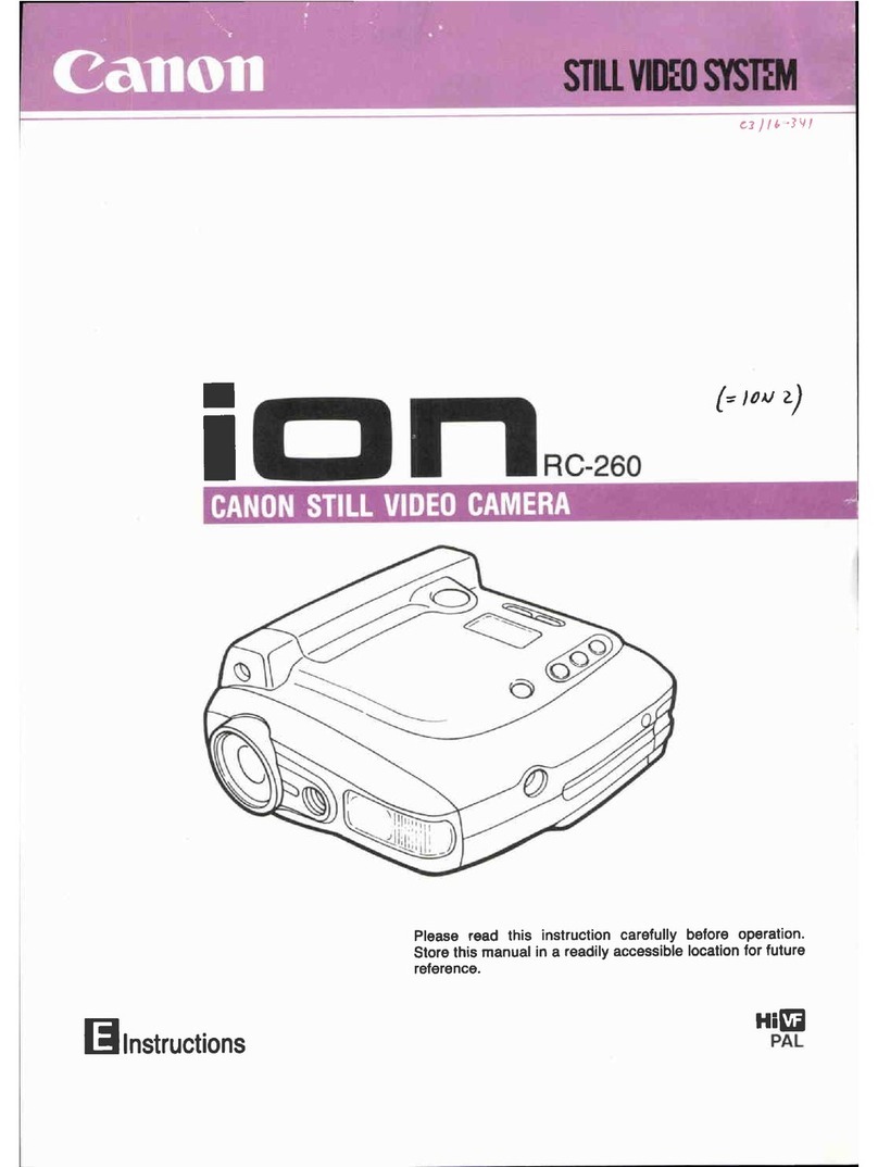
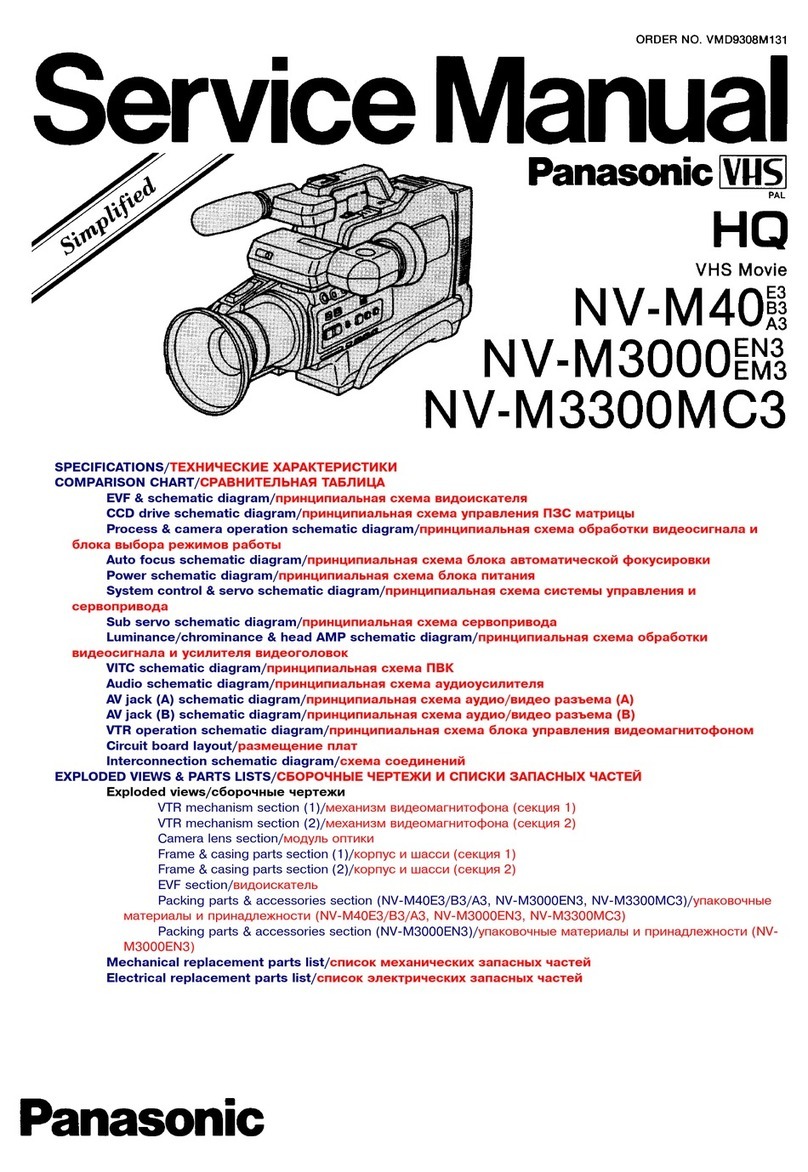
JVC GR-DVP3EG User manual

SERVICE MANUAL
DIGITAL VIDEO CAMERA
No. 86646
June 2001
This service manual is printed on 100% recycled paper.
COPYRIGHT © 2001 VICTOR COMPANY OF JAPAN, LTD.
GR-DVP3A-GY/A-SL/EA/ED/SH
SPECIFICATIONS
(The specifications shown pertain specifically to the model GR-DVP3A-GY/A-GYC/A-SL/EA/ED/SH)
Regarding service information other than these sections, refer to the GR-DVP3EG service manual (No. 86631).
Also, be sure to note important safety precautions provided in the service manual.
Camcorder
For General
Power supply : DC 6.3 V }(Using AC Power Adapter/Charger)
DC 7.2 V }(Using battery pack)
Power consumption
LCD monitor off, viewfinder on : Approx. 4.1 W
LCD monitor on, viewfinder off : Approx. 5.0 W
Dimensions (W x H x D) : 43 mm x 115 mm x 80 mm
(with the LCD monitor closed and the viewfinder pushed back in)
Weight : Approx. 340 g (without grip belt, battery and cassette)
Approx. 410 g (incl. grip belt, battery and cassette)
Operating temperature : 0°C to 40°C
Operating humidity : 35% to 80%
Storage temperature : –20°C to 50°C
Pickup : 1/4" CCD
Lens : F 1.8, f = 3.7 mm to 37 mm, 10:1 power zoom lens
(It is not possible to attach any lens filter or conversion lens.)
LCD monitor : 2" diagonally measured, LCD panel/TFT active matrix system
Viewfinder : Electronic viewfinder with 0.44" colour LCD
Speaker : Monaural
For Digital Video Camera
Format : DV format (SD mode)
Signal format : PAL standard
Recording/Playback format : Video: Digital component recording
: Audio: PCM digital recording, 32 kHz 4-channel (12-bit),
48 kHz 2-channel (16-bit)
Cassette : Mini DV cassette
Tape speed : SP: 18.8 mm/s
LP: 12.5 mm/s
Maximum recording time : SP: 80 min.
(using 80 min. cassette) LP: 120 min.
For Digital Still Camera
Storage media : SD Memory Card/MultiMediaCard
Compression system : Still image : JPEG (compatible)
Moving image : MPEG4 (compatible)
File size : 2 modes (XGA: 1024 x 768 pixels/VGA: 640 x 480 pixels)
Picture quality : 2 modes (FINE/STANDARD)
Approximate number of storable images
(with the provided memory card [8 MB], with Sound Effects pre-stored)
FINE : 37 (VGA), 16 (XGA)
STANDARD : 105 (VGA), 51 (XGA)
For other memory cards, see pg. 17.
For Connectors
AV
Video output : 1 V (p-p), 75 Ω, analogue
Audio output : 300 mV (rms), 1 kΩ, analogue, stereo
DV
Input/output : 4-pin, IEEE 1394 compliant
AC power adapter/charger AA-V100A, AA-V100EA, AA-V100ED or AA-V100SH
Power requirement : AC 110 V to 240 V`, 50 Hz/60 Hz
Power consumption : 23 W
Output
Charge : DC 7.2 V }, 1.2 A
VTR : DC 6.3 V }, 1.8 A
Dimensions (W x H x D) : 68 mm x 44 mm x 110 mm
Weight : Approx. 250 g (AA-V100A)
Approx. 260 g (AA-V100EA)
Approx. 250 g (AA-V100ED)
Approx. 325 g (AA-V100SH)
Docking Station CU-V507U
For General
Dimensions (W x H x D) : 48.4 mm x 36 mm x 79 mm
Weight : Approx. 53 g
For Connectors
PHONE
Headphone output :ø3.5 mm, stereo
USB : TYPE B
S-VIDEO OUT : Y: 1 V (p-p), 75 Ω, analogue output
C: 0.29 V (p-p), 75 Ω, analogue output
EDIT :ø3.5 mm, 2-pole
Specifications shown are for SP mode unless otherwise indicated. E & O.E. Design and specifications
subject to change without notice.

!
REF.
MODEL
GR-DVP3EG GR-DVP3A-SL GR-DVP3A-GY
GR-DVP3A-GYC
GR-DVP3EA GR-DVP3ED GR-DVP3SH
No. ITEM
1 PACKING CASE LY32303-001A LY32303-007A LY32303-008A LY32303-005A LY32303-006A
!
4 BATTERY PACK LY32203-001A LY32203-003A LY32203-001A LY32203-003A
!
5
AC POWER ADAPTER/CHARGER
LY20754-002B LY20754-008A LY20754-009A LY20754-005A LY20754-006B LY20754-007A
14 DC CORD LY32226-001A LY32226-002A LY32226-001A LY32226-002A
24 ADAPTER PLUG QAM0302-001 — — — — — —
25 POLY BAG QPA02003506 QPA02003006 QPA02003506
32 WARRANTY CARD BT54013-2 — — BT-59011-2 BT-56001-2 BT-59011-2 —
!
35 CONVERSION PLUG — PEMC1012-02 PEMC1012 ———
!
36 SHEET(CON.PLUG) — LYT0609-001A ———
37 GUARANTY CARD — — — BT-59012-1 — BT-59012-1 —
38 SER.NET CARD — — — — BT-56002-2 — —
1
TABLE OF CONTENTS
DIFFERENT TABLE ........................................................................................................................................................... 1 to 2
4. CHARTS AND DIAGRAMS (4-1 to 4-5)
4.1 BOTTOM SCHEMATIC DIAGRAM ............................................................................................................................... 4-1
4.2 BOTTOM CIRCUIT BOARD .......................................................................................................................................... 4-3
4.3 EJECT CIRCUIT BOARD ............................................................................................................................................. 4-5
5. PARTS LIST (5-1 to 5)
5.1 PACKING AND ACCESSORY ASSEMBLY <M1> ........................................................................................................ 5-1
5.2 FINAL ASSEMBLY <M2> .............................................................................................................................................. 5-3
The following table indicate main different points between models GR-DVP3EG, GR-DVP3A-SL, GR-DVP3A-GY, GR-DVP3A-GYC,
GR-DVP3EA, GR-DVP3ED and GR-DVP3SH.
The following table indicate different parts number between models GR-DVP3EG, GR-DVP3A-SL, GR-DVP3A-GY, GR-DVP3A-GYC,
GR-DVP3EA, GR-DVP3ED and GR-DVP3SH.
PACKING AND ACCESSORY ASSEMBLY <M1> Note: As for IB (INSTRUCTIONS), refer to sec.5.
Notes : Mark is same as left.
Mark — is not used.
Mark * reference model was also changed.
MODEL
GR-DVP3EG GR-DVP3A-SL GR-DVP3A-GY
GR-DVP3A-GYC
GR-DVP3EA GR-DVP3ED GR-DVP3SH
ITEM
AC POWER ADAPTER CHARGER AA-V100EG AA-V100A AA-V100A-S AA-V100EA AA-V100ED AA-V100SH
FINAL ASSEMBLY <M2>
!
REF.
MODEL
GR-DVP3EG GR-DVP3A-SL GR-DVP3A-GY
GR-DVP3A-GYC
GR-DVP3EA GR-DVP3ED GR-DVP3SH
No. ITEM
122 SPECIAL SCREW LY30018-055A LY30018-070A LY30018-055A LY30018-070A
125 UPPER CASE ASSY LY32292-001E LY32292-003C LY32292-001D LY32292-003C
126 GUIDE(MONI) LY32265-001C LY32265-002C LY32265-001C LY32265-002C
127 J.COVER(DV)ASSY LY43126-001D LY43126-002C LY43126-001D LY43126-002C
131 SUB OPE LY32198-001B LY32198-003B LY32198-001B LY32198-003B
133 SPECIAL SCREW LY30018-063A LY30018-0B7A LY30018-063A LY30018-0B7A
134 SPECIAL SCREW,X2 LY30018-092A LY30018-093A LY30018-092A LY30018-093A
135 COVER(JIG)ASSY LY43134-001C LY43134-002C LY43134-001C LY43134-002C
136 SPECIAL SCREW LY30018-055A LY30018-070A LY30018-055A LY30018-070A
137 SPECIAL SCREW,X2 LY30018-031A LY30018-032A LY30018-031A LY30018-032A
142 SHEET(CAUTION)1 LY41701-004A LY41701-002A LY41701-004A LY41701-002A
143 SHEET(CAUTION)2 LY42163-002B LY42163-003A LY42163-002B LY42163-003A
146 SPECIAL SCREW,X2 LY30018-0E4A LY30018-0C3A
150 SPECIAL SCREW,X2 LY30018-055A LY30018-070A LY30018-055A LY30018-070A
151 SPECIAL SCREW LY30018-055A LY30018-070A LY30018-055A LY30018-070A
152 SPECIAL SCREW LY30018-065A LY30018-0A2A LY30018-065A LY30018-0A2A
153 SPECIAL SCREW LY30018-055A LY30018-070A LY30018-055A LY30018-070A
154 SPECIAL SCREW LY30018-019A LY30018-026A LY30018-019A LY30018-026A
155 SPECIAL SCREW,X2 LY30018-0D5A LY30018-0D8A LY30018-0D5A LY30018-0D8A
185 LOWER CASE LY20756-001C LY20756-003A LY20756-001B LY20756-003A
197 BRACKET(H.S) LY32262-001A LY32262-001B LY32262-001A
205 SPECIAL SCREW LY30018-055A LY30018-070A
206 BOTTOM COVER LY20760-001F LY20760-003C LY20760-001D LY20760-003C
207 COVER(SD)ASSY LY32279-003A LY32279-002B LY32279-001C LY32279-003A LY32279-002B
208 SPECIAL SCREW,X2 LY30018-081A LY30018-043B LY30018-081A LY30018-043B
213 SPECIAL SCREW LY30018-0E1A LY30018-0E2A LY30018-0E1A LY30018-0E2A
2
Notes : Mark is same as left.
Mark —is not used.
Mark * reference model was also changed.
214 SPECIAL SCREW LY30018-065A LY30018-0A2A LY30018-065A LY30018-0A2A
223 SPECIAL SCREW LY30018-0A3A LY30018-060A LY30018-0A3A LY30018-060A
225 SPACER(A) ————*LY30029-0R1A ——
230 CASSETTE COVER LY20757-001B LY20757-002A LY20757-001B LY20757-002A
234 SPECIAL SCREW LY30018-0E3A LY30018-006B LY30018-0E3A LY30018-006B
!
240
CAUTION LABEL/SAFETY LABEL
LY41442-003A *—*—*—LY43149-003A *—*—
241 SHEET(C.COVER) LY43055-001B LY43055-001A
242 OPE.COVER UNIT LY20749-001C LY20749-001B
243 SPECIAL SCREW,X4 LY30018-065A LY30018-0A2A LY30018-065A LY30018-0A2A
244 SPECIAL SCREW,X2 LY30018-081A LY30018-070A LY30018-081A LY30018-070A
250 SPECIAL SCREW LY30018-0E3A LY30018-006B LY30018-0E3A LY30018-006B
!
REF.
MODEL
GR-DVP3EG GR-DVP3A-SL GR-DVP3A-GY
GR-DVP3A-GYC
GR-DVP3EA GR-DVP3ED GR-DVP3SH
No. ITEM
MECHANISM ASSEMBLY <M3>
!
REF.
MODEL
GR-DVP3EG GR-DVP3A-SL GR-DVP3A-GY
GR-DVP3A-GYC
GR-DVP3EA GR-DVP3ED GR-DVP3SH
No. ITEM
427 MINI SCREW YQ43893 *LY43023-001A * * * * *
MONITOR ASSEMBLY <M5>
!
REF.
MODEL
GR-DVP3EG GR-DVP3A-SL GR-DVP3A-GY
GR-DVP3A-GYC
GR-DVP3EA GR-DVP3ED GR-DVP3SH
No. ITEM
!
500 MONITOR ASSY
LYH20289-003B
LYH20289-006A
LYH20289-003B
LYH20289-006A
501 MONITOR CASE ASSY LY32263-001E *LY32263-002D LY32263-001C *LY32263-002D *
!
502 MONITOR COVER LY10297-001C LY10297-003B LY10297-001C LY10297-003B
506 HINGE COVER(U) LY32267-001A LY32267-002A LY32267-001A LY32267-002A
507 HINGE COVER(L) LY32268-001A LY32268-002A LY32268-001A LY32268-002A
509 SPECIAL SCREW,X2 LY30018-0D3A LY30018-0D9A LY30018-0D3A LY30018-0D9A
510 SPECIAL SCREW LY30018-081A LY30018-043B LY30018-081A LY30018-043B
512 SPECIAL SCREW,X2 LY30018-087A LY30018-0B7A LY30018-087A LY30018-0B7A
MAIN BOARD ASSEMBLY <01>
!
REF.
MODEL
GR-DVP3EG GR-DVP3A-SL GR-DVP3A-GY
GR-DVP3A-GYC
GR-DVP3EA GR-DVP3ED GR-DVP3SH
No. ITEM
OT6 SPACER(A) LY30029-0P9B *LY30029-0P9A * * * * *
BOTTOM BOARD ASSEMBLY <03>
!
REF.
MODEL
GR-DVP3EG GR-DVP3A-SL GR-DVP3A-GY
GR-DVP3A-GYC
GR-DVP3EA GR-DVP3ED GR-DVP3SH
No. ITEM
PW1 BOTTOM BOARD ASSY YB10329A1-02 *YB10329B1
* * * * *
D2803 ZENER DIODE —*EDZ6.8B
* * * * *
D2804 ZENER DIODE —*EDZ6.8B
* * * * *
D2805 ZENER DIODE —*EDZ6.8B
* * * * *
D2806 ZENER DIODE —*EDZ6.8B
* * * * *
D2808 ZENER DIODE —*EDZ6.8B
* * * * *
D2809 ZENER DIODE —*EDZ6.8B
* * * * *
D2810 ZENER DIODE —*EDZ6.8B
* * * * *
D2811 ZENER DIODE —*EDZ6.8B
* * * * *
R2811 MG RESISTOR —*
NRSA6AJ-0R0W
* * * * *
R2813 MG RESISTOR —*
NRSA6AJ-0R0W
* * * * *
R2819 MG RESISTOR —*
NRSA6AJ-0R0W
* * * * *
R2820 MG RESISTOR —*
NRSA6AJ-0R0W
* * * * *
R2821 MG RESISTOR —*
NRSA6AJ-0R0W
* * * * *
R2822 MG RESISTOR —*
NRSA6AJ-0R0W
* * * * *
C2805 CAPACITOR —*
NCBA1AK-104W
* * * * *
C2806 T CAPACITOR —*NBLJ0JM-106X
* * * * *
SECTION 6
AC POWER ADAPTER / CHARGER
CABINET ASSEMBLY <MA>
!
REF.
MODEL
GR-DVP3EG GR-DVP3A-SL GR-DVP3A-GY
GR-DVP3A-GYC
GR-DVP3EA GR-DVP3ED GR-DVP3SH
No. ITEM
!
3 AC POWER CORD YQ10531-006 PTY10067-036 PTY20080-035 PTY10067-037 YQ10531-006

Printed in Japan
VICTOR COMPANY OF JAPAN, LIMITED
VIDEO DIVISION
S40894

4-1
NO WEAR
CN303
BOTTOM
TO REG CON
CN107
CN301
TO J301
TO CN303
TO CN303
RS-151-X
GND
VCC
OUT
D2810 2
1
2
1
D2811 D2807
2
1
2
1
1
2
1
2
D2812
D2803 D2804
1
2
1
2
D2809
C2805
1
2
1
2
D2805 D2806
1
2
C2807
C
TO MMC/SD
1
2
3
5
4
ABCD
4.1 BOTTOM SCHEMATIC
DIAGRAM
SECTION 4
CHARTS AND DIAGRAMS

4-2
TO CN301
TO CN301
TO CN301
TO DDS
CN302
TO CN301
0
y20134001a rev0.1
NC
NC
TO CN302
STATION
DOCKING
TO
(CU-V507U-E)
1
2
1
2
1
2
C2806
C2808
1
22
1
C2809 D2808
0
0
0
0
0
0
R2813
R2819
R2820
R2821
R2822
R2811
EFGH
NOTE
1. How to find the page showing the continuative schematic diagram.
Example) To SYSCON : Refer to the GR-DVP3EG service manual (No. 86631).
To SYSCON : Refer to this service manual.
2. The mark means modified points.
3. When ordering parts, be sure to order according to the Part Number indicated in the Parts List.

4-3
4.2 BOTTOM CIRCUIT BOARD
BOTTOM PWB
03
FOIL SIDE(B)
YB10329-01-02

4-4
50
125
18
9
8
1
1
9
10
26
CN301
CN302
COMPONENT SIDE(A)
BOTTOM PWB
03
YB10329-01-02

4-5
4.3 EJECT CIRCUIT BOARD
EJECT PWB
06
FOIL SIDE(B)COMPONENT SIDE(A)
YB10329-01-02
EJECT PWB
06
YB10329-01-02
E. & O. E. No. 86646
(Sanwa)-M1D5S8
GR-DVP3A-SL/A-GY/A-GYC/EA/ED/SH

SECTION 5
PARTS LIST
SAFETY PRECAUTION
Parts identified by the symbol are critical for safety. Replace only with specified part numbers.
5.1 PACKING AND ACCESSORY ASSEMBLY <M1>
The instruction manual to be provided with this product will differ according to the destination.
5-1
26
1
2
25
FINAL ASSY
<M2>
27
28
29
30
31
36
37
38
32
LABEL
(SERIAL)
11
3
15
21
4
18
19
6
14
7
35
20
5
8
10
9
12
17
16

5-2
#REF No. PART No. PART NAME, DESCRIPTION
---------------- ----------------------- -----------------------------------------------------
MODEL MARK
GR-DVP3A-SL A
GR-DVP3A-GY B
GR-DVP3A-GYC C
GR-DVP3EA D
GR-DVP3ED E
GR-DVP3SH F
******************************
PACKING AND ACCESSORY ASSEMBLY <M1>
1 LY32303-005A PACKING CASE,D
LY32303-006A PACKING CASE,E,F
LY32303-007A PACKING CASE,A
LY32303-008A PACKING CASE,B,C
2 LY20763-001A CUSHION
3 LY30023-003A POLY BAG
!
4 LY32203-001A BATTERY PACK,BN-V107U,B,C,D
!
LY32203-003A BATTERY PACK,BN-V107U,A,E,F
!
5 LY20754-005A
AC POWER ADAPTER/CHARGER,AA-V100EA,D
!
LY20754-006B
AC POWER ADAPTER/CHARGER,AA-V100ED,E
!
LY20754-007A
AC POWER ADAPTER/CHARGER,AA-V100SH,F
!
LY20754-008A
AC POWER ADAPTER/CHARGER,AA-V100A,A
!
LY20754-009A
AC POWER ADAPTER/CHARGER,AA-V100A-S,B,C
6 LY20755-003A DOCKING STATION,CU-V507U
7 LY20750-001A REMOTE CONTROL UNIT,RM-V717U
8 LY32210-004A CD ROM
9 LY20762-001B GRIP BELT
10 LY20765-001B STRAP
11 QAM0342-002 MEMORY CARD
12 QQR0491-002 CORE FILTER,X2
14 LY32226-001A DC CORD,B,C,D
LY32226-002A DC CORD,A,E,F
15 QQR0917-002 CORE FILTER
16 QAM0347-001 CABLE ASSY,AUDIO/VIDEO CABLE
17 QQR0918-002 CORE FILTER
18 PEAC0428-150 CABLE ASSY,EDITING CABLE
19 QQR0491-002 CORE FILTER
20 – BATTERY,AAA(R03),X2
21 QPA01703005 POLY BAG
25 QPA02003506 POLY BAG,A,B,C,E,F
QPA02003006 POLY BAG,D
!
26 LYT0844-001A INST.BOOK(EN)
!
LYT0844-002A INST.BOOK(GE),A,B
!
LYT0844-003A INST.BOOK(FR),A,B
!
LYT0844-004A INST.BOOK(CH),A,B,C,E,F
!
LYT0844-005A INST.BOOK(RU),A,B,C,E,F
!
LYT0844-006A INST.BOOK(AR),A,B
!
27 LYT0761-001B INST.BOOK(SOFT.EN),D
!
LYT0806-001A INST.BOOK(SOFT.3LANG),C,E,F
!
LYT0843-001A INST.BOOK(SOFT.5LANG),A,B
28 LYT0378-003A SHEET(AGREMENT)
29 LYT0760-004A SHEET(ATT.)
30 LYT0796-015A SHEET(CORE)
31 LYT0796-016A SHEET(ATT.MIC)
32 BT-59011-2 WARRANTY CARD,C,E
BT-56001-2 WARRANTY CARD,D
!
35 PEMC1012 CONVERSION PLUG,B,C
!
PEMC1012-02 CONVERSION PLUG,A
!
36 LYT0609-001A SHEET(CON.PLUG),A,B,C
37 BT-59012-1 GUARANTY CARD,C,E
38 BT-56002-2 SER.NET CARD,D
•INSTRUCTIONS
EN ....... ENGLISH
GE ...... GERMAN
FR ....... FRENCH
CH ...... CHINESE
RU ....... RUSSIAN
AR ....... ARABIC

5.2 FINAL ASSEMBLY <M2>
239
230
231
232
agg
ee
m
d
cc
h
hh
a
w
233
234
108
107
106
115
110
109
114
112
111
211
101
105
104
104
102
h
j
102
103
108
250
239
240
186
19
185
202
213
212
206
2
RA
T
LA
208
223
219 2
0
238
y
2
0
217
245
246
248
249 236
237
237
235
236
b
EJECT
<06>
199
214
187
188
187
187
190
191
190
203
190
205
204
228
189
190
192
192
242
243
243 243
194
193A
194
241
243
244
244
247
193B
193D
193C
1
4
gb
x
BOTTO
M
<03>
12
3
146
2
0
2
0
14
5
254A
254
253
251D
251D 251C
251C
256
220
251A 251B
251C 251C
251C
252
CCD
<05>
OPTICAL BLOCK
SECTION
251
209
255
hh
f
e
dd
251J
251G
251F
251E
251H
251J
5-3

152
193
222
218
121
121
120
ELECTRONIC
VIEWFINDER
<M4>
222
225
RATING
LABEL
0
8
208
207
207A
207B
207C
7
215
216
8
7
199
199
122
A
198
197
196
d
k
bb
n
p
s
m
r
q
t
w
u
v
p
n
x
y
z
gg
aa
s
t
q
r
ff
aa
195
209
198 198 198
B
130
130A
130B
130C
132
156
137
137
126
131
172
174
173
165
165A
165A
165A
166
166
166
200
200
170
171
169
168
169
168A
MECHANISM
<M3>
MAIN
<01>
148
139
140
141A
141
149
144
124
127
MONITOR
<M5>
138
134
e
z
g
f
134 133
146
T
TOM
<
03>
AUDIO
<02>
123
220
4
6
201
ee
cc
bb
dd
ff
200
200
147
145
138
144
144
143
142
125A
125
157
154
j
k
c
135A
135
u
v
c
136
153
150
150
155
155
151
2
5-4

5-5
******************************
FINAL ASSEMBLY <M2>
101 LY20759-001A COVER(MIC)
102 LY30018-0A3A SPECIAL SCREW,X2
103 LY30018-0A2A SPECIAL SCREW
104 LY30029-0L7A SPACER(A),X2
105 LY43164-001A SHEET(MIC)
106 LY43106-001B SLIDE PLATE(B)ASSY
107 LY43225-001A TORSION SPRING
108 LY30018-0D2A SPECIAL SCREW,X2
109 LY32260-001D KNOB(SHUTTER)
110 LY30002-022A COMPRESSION SPRING
111 LY32228-001B COVER(UNDER)
112 LY30018-0A2A SPECIAL SCREW
114 LY43102-003B COVER(SHUT)ASSY
115 LY43104-001D GUIDE(SHUT)ASSY
120 LY32246-001A COVER(SHOE)
121 LY30018-0A2A SPECIAL SCREW,X2
122 LY30018-055A SPECIAL SCREW,B,C,D
LY30018-070A SPECIAL SCREW,A,E,F
123 LY30029-0N5A SPACER(A)
124 LY43196-001A SHEET(UPEER)
125 LY32292-001D UPPER CASE ASSY,B,C,D
LY32292-003C UPPER CASE ASSY,A,E,F
125A LY43210-002A LABEL(UPPER)
126 LY32265-001C GUIDE(MONI),B,C,D
LY32265-002C GUIDE(MONI),A,E,F
127 LY43126-001D JACK COVER(DV)ASSY,B,C,D
LY43126-002C JACK COVER(DV)ASSY,A,E,F
130 LY43064-001B KNOB(LOCK) ASSY
130A LY43081-001A SHAFT(LOCK)
130B LY43080-001A TORSION SPRING(LOCK)
130C LY43079-001A BRACKET(LOCK)
131 LY32198-001B SUB OPE,B,C,D
LY32198-003B SUB OPE,A,E,F
132 LY30018-081A SPECIAL SCREW
133 LY30018-0B7A SPECIAL SCREW,A,E,F
LY30018-063A SPECIAL SCREW,B,C,D
134 LY30018-093A SPECIAL SCREW,X2,A,E,F
LY30018-092A SPECIAL SCREW,X2,B,C,D
135 LY43134-001C COVER(JIG)ASSY,B,C,D
LY43134-002C COVER(JIG)ASSY,A,E,F
135A LY42350-002A FOOT
136 LY30018-055A SPECIAL SCREW,B,C,D
LY30018-070A SPECIAL SCREW,A,E,F
137 LY30018-031A SPECIAL SCREW,X2,B,C,D
LY30018-032A SPECIAL SCREW,X2,A,E,F
138 LY30018-099A SPECIAL SCREW,X2
139 LY32253-001B BASE
140 LY43107-001A SHAFT
141 LY43224-001A SPACER(B)ASSY
141A LY43221-001A S.SHEET(S.BASE)
142 LY41701-002A SHEET(CAUTION)1,A,E,F
LY41701-004A SHEET(CAUTION)1,B,C,D
143 LY42163-002B SHEET(CAUTION)2,B,C,D
LY42163-003A SHEET(CAUTION)2,A,E,F
144 LY42350-002A FOOT,X3
145 LY32254-001A BRACKET(BOTTOM)
146 LY30018-0E4A SPECIAL SCREW,X2,A,B,C,D,E
LY30018-0C3A SPECIAL SCREW,X2,F
147 LY30029-0K6A SPACER(A)
148 LY43176-001A SHEET(UPPER)1
149 LY43177-001A SHEET(UPPER)2
150 LY30018-055A SPECIAL SCREW,X2,B,C,D
LY30018-070A SPECIAL SCREW,X2,A,E,F
151 LY30018-055A SPECIAL SCREW,B,C,D
LY30018-070A SPECIAL SCREW,A,E,F
152 LY30018-0A2A SPECIAL SCREW,A,E,F
LY30018-065A SPECIAL SCREW,B,C,D
153 LY30018-055A SPECIAL SCREW,B,C,D
LY30018-070A SPECIAL SCREW,A,E,F
154 LY30018-019A SPECIAL SCREW,B,C,D
LY30018-026A SPECIAL SCREW,A,E,F
155 LY30018-0D5A SPECIAL SCREW,X2,B,C,D
LY30018-0D8A SPECIAL SCREW,X2,A,E,F
156 LY43127-001B STICKER(MONI.)
157 LY30029-0N3A SPACER(A)
165 LY43074-001C BRACKET(MECHA)ASSY
165A LY42796-001A BUSH,X3
166 LY30019-028A SPECIAL SCREW,X3
168 LY43190-001A SHIELD ASSY
168A LY42189-001A SPACER
169 LY30018-005A SPECIAL SCREW,X2
170 LY43083-001A BRACKET(PRE-REC)
171 QYSPSPT1414M SCREW
172 LY43159-001B SHEET(SHUTTER)
173 LY32001-002A LABEL(HOUSING)
174 LY40699-002A LABEL(PUSH)
185 LY20756-003A LOWER CASE,A,E,F
LY20756-001B LOWER CASE,B,C,D
186 LY32239-001C BUTTON(FUNC.)
187 LY30018-065A SPECIAL SCREW,X3
188 LY43056-001B KNOB(FUNC.)
189 LY43114-001A PLATE(C.C.HINGE)
190 LY30018-081A SPECIAL SCREW,X4
191 LY43125-001A WINDOW(W/B)ASSY
192 LY30018-065A SPECIAL SCREW,X2
193 LY32280-001C BATTERY LOCK ASSY
193A LY30029-0K9A SPACER(A)
193B LY30029-0N1A SPACER(A)
193C LY30002-038A COMPRESSION SPRING
193D LY30029-0M9A SPACER(A)
194 LY30018-031A SPECIAL SCREW,X2
195 LY31998-002A HOT SHOE
196 QAL0336-001 FPC,AUDIO CN202-HOT SHOE
197 LY32262-001A BRACKET(H.S),A,B,C,E,F
LY32262-001B BRACKET(H.S),D
198 LY30018-081A SPECIAL SCREW,X4
199 LY30018-081A SPECIAL SCREW,X3
200 LY30018-055A SPECIAL SCREW,X4
201 LY30018-065A SPECIAL SCREW
202 LY32197-001C MICROPHONE
203 LY32247-001A COVER(M.ADJ)
204 LY30018-065A SPECIAL SCREW
205 LY30018-055A SPECIAL SCREW,A,B,C,D,E
LY30018-070A SPECIAL SCREW,F
206 LY20760-001D BOTTOM COVER,B,C,D
LY20760-003C BOTTOM COVER,A,E,F
207 LY32279-003A COVER(SD)ASSY,D
LY32279-002B COVER(SD)ASSY,A,E,F
LY32279-001C COVER(SD)ASSY,B,C
207A LY32242-002A BRACKET(SD)
207B LY43111-001A SHAFT(SD.COVER)
207C LY43047-001B TORSION SPRING
208 LY30018-043B SPECIAL SCREW,X2,A,E,F
LY30018-081A SPECIAL SCREW,X2,B,C,D
209 LY30029-0K5A SPACER(A),X2
211 LY32255-001C HOOD
212 LY43169-001B HOLDER(SD CON)
213 LY30018-0E2A SPECIAL SCREW,A,E,F
LY30018-0E1A SPECIAL SCREW,B,C,D
214 LY30018-0A2A SPECIAL SCREW,A,E,F
LY30018-065A SPECIAL SCREW,B,C,D
215 LY30018-081A SPECIAL SCREW
216 QYSPSPT1725D SCREW
217 LY43084-001A SHEET(B.COVER)
218 LY30018-065A SPECIAL SCREW
219 LY43216-001A SPACER(LOW-BOTT)
220 LY30029-0L3A SPACER(A),X2
222 LY30018-081A SPECIAL SCREW,X2
223 LY30018-0A3A SPECIAL SCREW,B,C,D
LY30018-060A SPECIAL SCREW,A,E,F
225 LY30029-0R1A SPACER(A),D
228 LY30029-0Q2A SPACER(A)
230 LY20757-002A CASSETTE COVER,A,E,F
LY20757-001B CASSETTE COVER,B,C,D
231 LY32244-001B ARM ASSY(1)
232 LY30018-031A SPECIAL SCREW
233 LY30018-081A SPECIAL SCREW
234 LY30018-006B SPECIAL SCREW,A,E,F
LY30018-0E3A SPECIAL SCREW,B,C,D
235 LY32245-001B ARM ASSY(2)
236 LY30018-081A SPECIAL SCREW,X2
237 LY30018-081A SPECIAL SCREW,X2
238 LY30018-081A SPECIAL SCREW
239 LY43113-001A SHAFT(C.COVER),X2
!
240 LY43149-003A SAFETY LABEL,D
241 LY43055-001A SHEET(C.COVER),E,F
LY43055-001B SHEET(C.COVER),A,B,C,D
242 LY20749-001B OPE.COVER UNIT
243 LY30018-0A2A SPECIAL SCREW,X4,A,E,F
LY30018-065A SPECIAL SCREW,X4,B,C,D
244 LY30018-081A SPECIAL SCREW,X2,B,C,D
LY30018-070A SPECIAL SCREW,X2,A,E,F
245 LY30029-0L5C SPACER(A)
246 LY43198-001B SHEET(OPE-SD)
247 LY30029-0N8A SPACER(A)
248 LY43200-001A SHEET(ARM1)
249 LY43201-001A SHEET(ARM2)
250 LY30018-006B SPECIAL SCREW,A,E,F
LY30018-0E3A SPECIAL SCREW,B,C,D
252 LY43160-001A SHEET(CCD PWB)
253 LY30029-0P6A SPACER(A)
254 LY43075-001C OP BRACKET ASSY
254A LY41675-001A RUBBER
255 LY30018-0D7A SPECIAL SCREW
256 LY30029-0L4A SPACER(A)
– OPTICAL BLOCK SECTION –
251 J0D-201A OPTICAL BLOCK ASSY
251A LY32158-001A ZOOM MOTOR
251B LY32157-001A FOCUS MOTOR
251C LY30727-006B SCREW,X5
251D LY30727-001A SCREW,X2
251E LY42983-001A OPTICAL LPF
251F LY42948-001B SHEET
251G LYH40167-001B CCD BASE ASSY
251H LY32162-001A IRIS UNIT
251J QYSPSGU1740Z SCREW,X2
#REF No. PART No. PART NAME, DESCRIPTION # REF No. PART No. PART NAME, DESCRIPTION
---------------- ----------------------- ----------------------------------------------------- ----------------- ----------------------- -----------------------------------------------------

SERVICE MANUAL
No. 86631
May 2001
GR-DVP1EG/EK,DVP3EG/EK
SPECIFICATIONS
DIGITAL VIDEO CAMERA
Printed in Japan
This service manual is printed on 100% recycled paper.
COPYRIGHT © 2001 VICTOR COMPANY OF JAPAN, LTD.
GR-DVP1EG/EK,DVP3EG/EK No. 86631
VICTOR COMPANY OF JAPAN, LIMITED
VIDEO DIVISION
S40894
Camcorder
For General
Power supply : DC 6.3 V }(Using AC Power Adapter/Charger)
DC 7.2 V }(Using battery pack)
Power consumption
LCD monitor off, viewfinder on : Approx. 4.1 W
LCD monitor on, viewfinder off : Approx. 5.0 W
Dimensions (W x H x D) : 43 mm x 115 mm x 80 mm
(with the LCD monitor closed and the viewfinder pushed back in)
Weight : Approx. 340 g (without grip belt, battery and cassette)
Approx. 410 g (incl. grip belt, battery and cassette)
Operating temperature : 0°C to 40°C
Operating humidity : 35% to 80%
Storage temperature : –20°C to 50°C
Pickup : 1/4" CCD
Lens : F 1.8, f = 3.7 mm to 37 mm, 10:1 power zoom lens
(It is not possible to attach any lens filter or conversion lens.)
LCD monitor : 2" diagonally measured, LCD panel/TFT active matrix system
Viewfinder : Electronic viewfinder with 0.44" colour LCD
Speaker : Monaural
For Digital Video Camera
Format : DV format (SD mode)
Signal format : PAL standard
Recording/Playback format : Video: Digital component recording
: Audio: PCM digital recording, 32 kHz 4-channel (12-bit),
48 kHz 2-channel (16-bit)
Cassette : Mini DV cassette
Tape speed : SP: 18.8 mm/s
LP: 12.5 mm/s
Maximum recording time : SP: 80 min.
(using 80 min. cassette) LP: 120 min.
For Digital Still Camera
Storage media : SD Memroy Card/MultiMediaCard
Compression system : Still image : JPEG (compatible)
Moving image : MPEG4 (compatible)
File size : 2 modes (XGA: 1024 x 768 pixels/VGA: 640 x 480 pixels)
Picture quality : 2 modes (FINE/STANDARD)
Approximate number of storable images
(with the provided memory card [8 MB], with Sound Effects pre-stored)
FINE : 37 (VGA), 16 (XGA)
STANDARD : 105 (VGA), 51 (XGA)
For other memory cards, see pg. 17.
For Connectors
AV
Video output : 1 V (p-p), 75 Ω, analogue
Audio output : 300 mV (rms), 1 kΩ, analogue, stereo
DV
Input/output (GR-DVP3 only) : 4-pin, IEEE 1394 compliant
Output (GR-DVP1 only) : 4-pin, IEEE 1394 compliant
AC power adapter/charger AA-V100EG or AA-V100EK
Power requirement : AC 110 V to 240 V `, 50 Hz/60 Hz
Power consumption : 23 W
Output
Charge : DC 7.2 V }, 1.2 A
VTR : DC 6.3 V }, 1.8 A
Dimensions (W x H x D) : 68 mm x 44 mm x 110 mm
Weight : Approx. 250 g (AA-V100EG)
: Approx. 325 g (AA-V100EK)
Docking Station CU-V507U
For General
Dimensions (W x H x D) : 48.4 mm x 36 mm x 79 mm
Weight : Approx. 53 g
For Connectors
PHONE
Headphone output :ø3.5 mm, stereo
USB : TYPE B
S-VIDEO OUT : Y: 1 V (p-p), 75 Ω, analogue output
C: 0.29 V (p-p), 75 Ω, analogue output
EDIT :ø3.5 mm, 2-pole
Specifications shown are for SP mode unless otherwise indicated. E & O.E. Design and specifications subject
to change without notice.

Important Safety Precautions
INSTRUCTIONS
1. DISASSEMBLY
1.1 BEFORE ASSEMBLY AND DISASSEMBLY ................................ 1-1
1.1.1 Precautions ............................................................................ 1-1
1.1.2 Assembly and disassembly .................................................... 1-1
1.1.3 Destination of connectors ...................................................... 1-1
1.1.4 Disconnection of Connectors (Wires) .................................... 1-1
1.2 JIGS AND TOOLS REQUIRED FOR DISASSEMBLY,
ASSEMBLY AND ADJUSTMENT ................................................. 1-2
1.2.1 Tools required for adjustments ............................................... 1-2
1.3 DISASSEMBLY/ASSEMBLY OF CABINET PARTS AND
BOARD ASSEMBLY ..................................................................... 1-2
1.3.1 Disassembly flow chart .......................................................... 1-2
1.3.2 Disassembly method .............................................................. 1-3
1.4 DISASSEMBLY OF 5MONITOR ASSEMBLY ............................. 1-8
1.4.1 5Monitor assembly/Hinge assembly .................................... 1-8
1.4.2 Hinge assembly ...................................................................... 1-8
1.5 DISASSEMBLY OF !E. VF ASSEMBLY ..................................... 1-9
1.5.1 !E. VF assembly ................................................................... 1-9
1.6 DISASSEMBLY OF #OP BLOCK ASSEMBLY/CCD
BOARD ASSEMBLY ................................................................... 1-10
1.6.1 Precautions .......................................................................... 1-10
1.6.2
How to remove OP block assembly and CCD board assembly .
1-10
1.6.3
How to install #OP block assembly and CCD board assembly
1-10
1.6.4 Replacement of service parts .............................................. 1-10
1.7 EMERGENCY DISPLAY ............................................................ 1-11
1.8 SERVICE KNOW-HOW .............................................................. 1-12
1.9 SERVICE NOTE ......................................................................... 1-14
2. MECHANISM ADJUSTMENT
2.1 PRELIMINARY REMARKS ON ADJUSTMENT AND REPAIR .... 2-1
2.1.1 Precautions ............................................................................ 2-1
2.1.2 Notes on procedure for disassemby/assembly ...................... 2-1
2.2 JIGS AND TOOLS REQUIRED FOR DISASSEMBLY,
ASSEMBLY AND ADJUSTMENT ................................................. 2-2
2.2.1 Tools required for adjustments ............................................... 2-2
2.3 DISASSEMBLY/ASSEMBLY OF MECHANISM ASSEMBLY ........ 2-3
2.3.1 General statement .................................................................. 2-3
2.3.2 Explanation of mechanism mode ........................................... 2-3
2.3.3 Mechanism timing chart ......................................................... 2-4
2.4 DISASSEMBLING PROCEDURE TABLE .................................... 2-5
2.4.1 Disassembly/assembly ........................................................... 2-7
2.4.2 List of procedures for disassembly ....................................... 2-13
2.5 CHECKUP AND ADJUSTMENT OF MECHANISM PHASE ...... 2-14
2.6 MECHANISM ADJUSTMENTS .................................................. 2-15
2.6.1 Adjustment of the slide guide plate ...................................... 2-15
2.6.2 Adjustment of the Tension Arm and Pad Arm Assemblies ... 2-16
2.6.3 Adjustment of the Slide Lever 2 ........................................... 2-16
2.7 JIG CONNECTOR CABLE CONNECTION ................................ 2-17
2.8 SERVICE NOTE ......................................................................... 2-18
3. ELECTRICAL ADJUSTMENT
3.1 PRECAUTION .............................................................................. 3-1
3.2 SETUP ......................................................................................... 3-2
TABLE OF CONTENTS
Section Title Page Section Title Page
4. CHARTS AND DIAGRAMS
NOTES OF SCHEMATIC DIAGRAM ................................................. 4-1
CIRCUIT BOARD NOTES .................................................................. 4-2
4.1 BOARD INTERCONNECTIONS ................................................. 4-3
4.2 SYSCON-CPU SCHEMATIC DIAGRAM .................................... 4-5
4.3 MSD-CPU SCHEMATIC DIAGRAM ............................................ 4-7
4.4 MDA SCHEMATIC DIAGRAM ..................................................... 4-9
4.5 DV MAIN SCHEMATIC DIAGRAM ............................................ 4-11
4.6 PRE/REC SCHEMATIC DIAGRAM .......................................... 4-13
4.7 VIDEO OUT SCHEMATIC DIAGRAM ....................................... 4-15
4.8 CAM. DSP SCHEMATIC DIAGRAM ......................................... 4-17
4.9 TG/VDR SCHEMATIC DIAGRAM ............................................. 4-19
4.10 VF MAIN SCHEMATIC DIAGRAM .......................................... 4-21
4.11 REG CON SCHEMATIC DIAGRAM ........................................ 4-23
4.12 REG SCHEMATIC DIAGRAM ................................................. 4-25
4.13 MONITOR MAIN SCHEMATIC DIAGRAM .............................. 4-27
4.14 DSC SCHEMATIC DIAGRAM ................................................. 4-29
4.15 AUDIO MP3 SCHEMATIC DIAGRAM ..................................... 4-31
4.16 USBDRV SCHEMATIC DIAGRAM.......................................... 4-33
4.17 W/B SCHEMATIC DIAGRAM .................................................. 4-35
4.18 CCD SCHEMATIC DIAGRAM ................................................. 4-36
4.19 WBSE/SW SCHEMATIC DIAGRAM ....................................... 4-37
4.20 AUDIO AD/DA SCHEMATIC DIAGRAM ................................. 4-39
4.21 MAIN AUDIO SCHEMATIC DIAGRAM ................................... 4-41
4.22 OPDRV SCHEMATIC DIAGRAM ............................................ 4-43
4.23 BOTTOM SCHEMATIC DIAGRAM ......................................... 4-45
4.24 MONITOR SCHEMATIC DIAGRAM ........................................ 4-47
4.25 OPE.COVER UNIT AND SUB OPE. UNIT SCHEMATIC
DIAGRAMS ............................................................................. 4-49
4.26 MAIN CIRCUIT BOARD.......................................................... 4-51
4.27 AUDIO CIRCUIT BOARD ....................................................... 4-57
4.28 BOTTOM CIRCUIT BOARD ................................................... 4-59
4.29 MONITOR CIRCUIT BOARD .................................................. 4-61
4.30 CCD AND EJECT CIRCUIT BOARDS ................................... 4-62
4.31 VOLTAGE CHARTS ................................................................ 4-63
4.32 POWER SYSTEM BLOCK DIAGRAM .................................... 4-65
4.33 VIDEO SYSTEM BLOCK DIAGRAM ...................................... 4-67
5. PARTS LIST
5.1 PACKING AND ACCESSORY ASSEMBLY <M1> ....................... 5-1
5.2 FINAL ASSEMBLY <M2> ............................................................ 5-2
5.3 MECHANISM ASSEMBLY <M3> ................................................ 5-6
5.4 ELECTRONIC VIEWFINDER ASSEMBLY <M4> ........................ 5-8
5.5 MONITOR ASSEMBLY <M5> ..................................................... 5-9
5.6 ELECTRICAL PARTS LIST ........................................................ 5-10
MAIN BOARD ASSEMBLY <01> ................................................... 5-10
AUDIO BOARD ASSEMBLY <02> ................................................. 5-18
BOTTOM BOARD ASSEMBLY <03> ............................................. 5-21
MONITOR BOARD ASSEMBLY <04> ............................................ 5-21
CCD BOARD ASSEMBLY <05> ..................................................... 5-21
EJECT BOARD ASSEMBLY <06> ................................................. 5-21
6. AC POWER ADAPTER (AA-V100EG/EK)
6.1 CABINET ASSEMBLY <MA> ...................................................... 6-1
6.2 SCHEMATIC DIAGRAM ............................................................... 6-2
6.3 CIRCUIT BOARD ......................................................................... 6-4
6.4 ELECTRICAL PARTS LIST .......................................................... 6-5
MAIN & TERMINAL BOARD ASSEMBLY <91> ............................... 6-5
GR-DVP1EG GR-DVP1EK GR-DVP3EG GR-DVP3EK
DV INPUT NOT USED NOT USED USED USED
AC ADAPTER CHARGER AA-V100EG AA-V100EK AA-V100EG AA-V100EK
BODY COLOR SILVER SILVER DARK GRAY/SILVER DARK GRAY/SILVER
BATTERY PACK (COLOR) SILVER SILVER DARK GRAY DARK GRAY
The following table lists the differing points between Models GR-DVP1EG/EK and GR-DVP3EG/EK in this series.

Important Safety Precautions
Prior to shipment from the factory, JVC products are strictly inspected to conform with the recognized product safety and electrical codes of the
countries in which they are to be sold. However, in order to maintain such compliance, it is equally important to implement the following precautions
when a set is being serviced.
Fig.1
1. Locations requiring special caution are denoted by labels and in-
scriptions on the cabinet, chassis and certain parts of the product.
When performing service, be sure to read and comply with these
and other cautionary notices appearing in the operation and serv-
ice manuals.
2. Parts identified by the !symbol and shaded ( ) parts are
critical for safety.
Replace only with specified part numbers.
Note: Parts in this category also include those specified to com-
ply with X-ray emission standards for products using
cathode ray tubes and those specified for compliance
with various regulations regarding spurious radiation
emission.
3. Fuse replacement caution notice.
Caution for continued protection against fire hazard.
Replace only with same type and rated fuse(s) as specified.
4. Use specified internal wiring. Note especially:
1) Wires covered with PVC tubing
2) Double insulated wires
3) High voltage leads
5. Use specified insulating materials for hazardous live parts. Note
especially:
1) Insulation Tape 3) Spacers 5) Barrier
2) PVC tubing 4) Insulation sheets for transistors
6. When replacing AC primary side components (transformers, power
cords, noise blocking capacitors, etc.) wrap ends of wires securely
about the terminals before soldering.
Power cord
Fig.2
10. Also check areas surrounding repaired locations.
11. Products using cathode ray tubes (CRTs)
In regard to such products, the cathode ray tubes themselves, the
high voltage circuits, and related circuits are specified for compli-
ance with recognized codes pertaining to X-ray emission.
Consequently, when servicing these products, replace the cath-
ode ray tubes and other parts with only the specified parts. Under
no circumstances attempt to modify these circuits.
Unauthorized modification can increase the high voltage value and
cause X-ray emission from the cathode ray tube.
12. Crimp type wire connector
In such cases as when replacing the power transformer in sets
where the connections between the power cord and power trans-
former primary lead wires are performed using crimp type connec-
tors, if replacing the connectors is unavoidable, in order to prevent
safety hazards, perform carefully and precisely according to the
following steps.
1) Connector part number : E03830-001
2) Required tool : Connector crimping tool of the proper type which
will not damage insulated parts.
3) Replacement procedure
(1) Remove the old connector by cutting the wires at a point
close to the connector.
Important : Do not reuse a connector (discard it).
Fig.7
cut close to connector
Fig.3
(2) Strip about 15 mm of the insulation from the ends of the
wires. If the wires are stranded, twist the strands to avoid
frayed conductors.
15 mm
Fig.4
(3) Align the lengths of the wires to be connected. Insert the
wires fully into the connector.
Connector
Metal sleeve
Fig.5
(4) As shown in Fig.6, use the crimping tool to crimp the metal
sleeve at the center position. Be sure to crimp fully to the
complete closure of the tool.
I
•Precautions during Servicing
7. Observe that wires do not contact heat producing parts (heatsinks,
oxide metal film resistors, fusible resistors, etc.)
8. Check that replaced wires do not contact sharp edged or pointed
parts.
9. When a power cord has been replaced, check that 10-15 kg of
force in any direction will not loosen it.
1.25
2.0
5.5
Crimping tool
Fig.6
(5) Check the four points noted in Fig.7.
Not easily pulled free Crimped at approx. center
of metal sleeve
Conductors extended
Wire insulation recessed
more than 4 mm
S40888-01

•Safety Check after Servicing
Examine the area surrounding the repaired location for damage or deterioration. Observe that screws, parts and wires have been returned
to original positions, Afterwards, perform the following tests and confirm the specified values in order to verify compliance with safety
standards.
1. Insulation resistance test
Confirm the specified insulation resistance or greater between power cord plug prongs and exter-
nally exposed parts of the set (RF terminals, antenna terminals, video and audio input and output
terminals, microphone jacks, earphone jacks, etc.). See table 1 below.
2. Dielectric strength test
Confirm specified dielectric strength or greater between power cord plug prongs and exposed acces-
sible parts of the set (RF terminals, antenna terminals, video and audio input and output terminals,
microphone jacks, earphone jacks, etc.). See table 1 below.
3. Clearance distance
When replacing primary circuit components, confirm specified clearance distance (d), (d’) be-
tween soldered terminals, and between terminals and surrounding metallic parts. See table 1
below.
4. Leakage current test
Confirm specified or lower leakage current between earth ground/power cord plug prongs and
externally exposed accessible parts (RF terminals, antenna terminals, video and audio input and
output terminals, microphone jacks, earphone jacks, etc.).
Measuring Method : (Power ON)
Insert load Z between earth ground/power cord plug prongs and externally exposed accessible
parts. Use an AC voltmeter to measure across both terminals of load Z. See figure 9 and following
table 2.
5. Grounding (Class 1 model only)
Confirm specified or lower grounding impedance between earth pin in AC inlet and externally exposed accessible parts (Video in, Video out,
Audio in, Audio out or Fixing screw etc.).
Measuring Method:
Connect milli ohm meter between earth pin in AC inlet and exposed accessible parts. See figure 10 and grounding specifications.
Fig. 10
Fig. 9
Fig. 8
Table 1 Specifications for each region
Table 2 Leakage current specifications for each region
Note: These tables are unofficial and for reference only. Be sure to confirm the precise values for your particular country and locality.
II
S40888-01
ab
c
V
A
Externally
exposed
accessible part
Z

1-1
(1) (2) (3) (4) (5)
SECTION 1
DISASSEMBLY
1.1.4 Disconnection of Connectors (Wires)
Connector
Pull both ends of the connector in the arrow direction, re-
move the lock and disconnect the flat wire.
1.1 BEFORE ASSEMBLY AND DISASSEMBLY
1.1.1 Precautions
1. Be sure to remove the power supply unit prior to mount-
ing and soldering of parts.
2. When removing a component part that needs to discon-
nect the connector and to remove the screw for remov-
ing itself, first disconnect the connecting wire from the
connector and then remove the screw beforehand.
3. When connecting and disconnecting the connectors, be
careful not to damage the wire.
4. Carefully remove and handle the part to which some
spacer or shield is attached for reinforcement or insula-
tion.
5. When replacing chip parts (especially IC parts), desolder
completely first (to prevent peeling of the pattern).
6. Tighten screws properly during the procedures.
Unless specified otherwise, tighten screws at a torque
of 0.078N•m(0.8kgf•cm).
1.1.2 Assembly and disassembly
(1) Indicate the disassembly steps. When assembling, per-
form in the reverse order of these steps. This number
corresponds to the number in the disassembly diagram.
(2) Indicates the name of disassembly/assembly parts.
(3) Indicates the number in the disassembly diagram.
(4) Indicates parts and points such as screws, washers,
springs which must be removed during disassembly/
assembly.
Symbol Name, Point
S Screw
L Lock, Pawl, Hook
SD Soldering
CN Connector
(Example)
• 2 (S1) : Remove the two screws (S1) for removing the
part 1.
• CN 1a: Disconnect the connector 1a.
• SD1 : Unsolder at the point SD1.
(5) Precautions on disassembly/assembly.
1.1.3 Destination of connectors
Note:
Three kinds of double-arrows in connection tables re-
spectively show kinds of connector/wires.
↔: Wire
⇔: Flat wire (FPC, FFC)
: Board to Board connector
[Example]
NOTE:
Remove the parts marked in
.
Fig. 1-1-1 Connector 1
Connector
Flat wire
Fig. 1-1-2 Connector 2
Connector
Flat wire
Extend the locks in the direction of the arrow for unlocking
and then pull out the wire. After removing the wire, immedi-
ately restore the locks to their original positions because
the locks are apt to come off the connector.
B-B connector
Pull the board by both the sides in the direction of the ar-
row for disconnecting the B-B connector.
Fig. 1-1-3 Connector 3
Connector
Connector
Fig. 1-1-4 Connector 4
Connector
1COVER(UNDER) Fig.1-3-1 (S1)—
2COVER(SHOE) Fig.1-3-2 2(S2),(L2a),(L2b) —
3
MIC COVER ASSY
(S3a),2(S3b) —
STEP
No. PART Fig.No. POINT NOTE
CONN.
No. Pin No.
CONNECTOR
CN4a MAIN CN107 BOTTOM CN301 50
CN4b MAIN CN112 ⇔SUB OPE UNIT CN112 7

1-2
1.2 JIGS AND TOOLS REQUIRED FOR DISASSEMBLY,
ASSEMBLY AND ADJUSTMENT
1.2.1 Tools required for adjustments
1. Torque driver
Be sure to use to fastening the mechanism and exterior
parts because those parts must strictly be controlled for
tightening torque.
2. Bit
This bit is slightly longer than those set in conventional
torque drivers.
3. Tweezers
To be used for removing and installing parts and wires.
4. Chip IC replacement jig
To be used for adjustment of the camera system.
5. Cleaning cloth
Recommended cleaning cloth to wipe down the video
heads, mechanism (tape transport system), optical lens
surface.
1.3 DISASSEMBLY/ASSEMBLY OF CABINET PARTS
AND BOARD ASSEMBLY
1.3.1 Disassembly flow chart
This flowchart indicates the disassembly step for the cabi-
net parts and board assembly in order to gain access to
item(s) to be serviced. When reassembling, perform the
step(s) in reverse order.
Table 1-2-1
Table 1-3-1
Torque Driver
YTU94088
1
Bit
YTU94088-003
2
3
Chip IC Replacement Jig
PTS40844-2
4
5
Cleaning Cloth
KSMM-01
Tweezers
P-895
2
3
1
4
5
6
8
#
$
0
9
7
!
COVER (UNDER)
COVER (SHOE)
MIC COVER ASSY
UPPER CASE ASSY
(Inc.MONITOR ASSY)
MONITOR ASSY
SHUTTER ASSY
LOWER CASE ASSY
(Inc.MICROPHONE
/E.VF UNIT
/AUDIO BOARD ASSY
/OP BLOCK ASSY)
MAIN BOARD ASSY
MECHANISM ASSY
MICROPHONE
E. VF UNIT
AUDIO BOARD ASSY
OP BLOCK ASSY
SHOE ASSY
@
This manual suits for next models
6
Table of contents
Other JVC Camcorder manuals