manuals.online logo
Brands
  1. Home
  2. •
  3. Brands
  4. •
  5. JVC
  6. •
  7. Car Receiver
  8. •
  9. JVC KW-XR414 Guide

JVC KW-XR414 Guide

Other JVC Car Receiver manuals

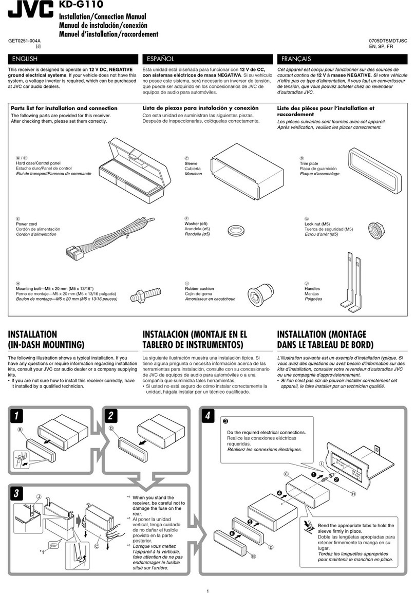
JVC KS-FX301S User manual

JVC

JVC KS-FX301S User manual

JVC KD-T801BT User manual

JVC

JVC KD-T801BT User manual

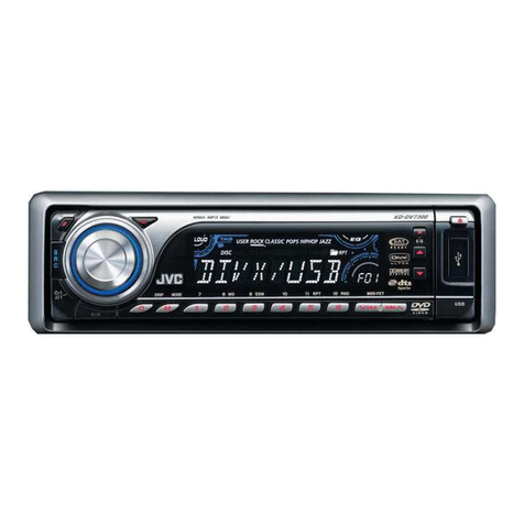
JVC KD-AV7100JW User manual

JVC

JVC KD-AV7100JW User manual

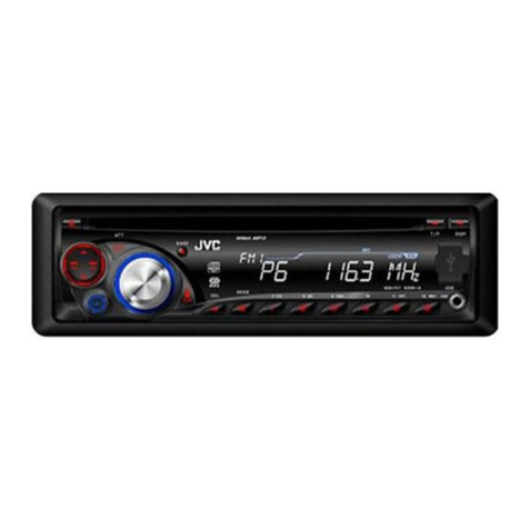
JVC KD-R536 User manual

JVC

JVC KD-R536 User manual

JVC KW-NT1 - Navigation System With DVD player Guide

JVC

JVC KW-NT1 - Navigation System With DVD player Guide

JVC KD-SX947R User manual

JVC

JVC KD-SX947R User manual

JVC KD-G511 Guide

JVC

JVC KD-G511 Guide

JVC KD-AV7100 Guide

JVC

JVC KD-AV7100 Guide

JVC KS-F185 Administrator Guide

JVC

JVC KS-F185 Administrator Guide

JVC KD-R701 Guide

JVC

JVC KD-R701 Guide

JVC KS F100 User manual

JVC

JVC KS F100 User manual

JVC KD-APD38 User manual

JVC

JVC KD-APD38 User manual

JVC KS-LX200R User manual

JVC

JVC KS-LX200R User manual

JVC KD-AVX2 - DVD Player With LCD Monitor User manual

JVC

JVC KD-AVX2 - DVD Player With LCD Monitor User manual

JVC KD-S5M User manual

JVC

JVC KD-S5M User manual

JVC KD-DB56 Guide

JVC

JVC KD-DB56 Guide

JVC KD-R538 User manual

JVC

JVC KD-R538 User manual

JVC KD-SC800 User manual

JVC

JVC KD-SC800 User manual

JVC KD-R900 User manual

JVC

JVC KD-R900 User manual

JVC KD-LX300 User manual

JVC

JVC KD-LX300 User manual

JVC KD-PDR51 User manual

JVC

JVC KD-PDR51 User manual

JVC KD-S891R User manual

JVC

JVC KD-S891R User manual

JVC KW-AVX840 User manual

JVC

JVC KW-AVX840 User manual

JVC KD-T920BTS User manual

JVC

JVC KD-T920BTS User manual

Popular Car Receiver manuals by other brands

Linear Series LS5050 Operation and installation manual

Linear Series

Linear Series LS5050 Operation and installation manual

Kenwood KRC-160 instruction manual

Kenwood

Kenwood KRC-160 instruction manual

Sony XR-CA430X Service manual

Sony

Sony XR-CA430X Service manual

T+A Elektroakustik K1 CD-RECEIVER operating instructions

T+A Elektroakustik

T+A Elektroakustik K1 CD-RECEIVER operating instructions

SoundMax SM-CDM1052 instruction manual

SoundMax

SoundMax SM-CDM1052 instruction manual

Xtrons HD107HD user manual

Xtrons

Xtrons HD107HD user manual

Mopar RB3 manual

Mopar

Mopar RB3 manual

Clarion ADDZEST DMZ615 owner's manual

Clarion

Clarion ADDZEST DMZ615 owner's manual

Sony XAV-601BT Specifications

Sony

Sony XAV-601BT Specifications

PIE GM12-POD/S Operation manual

PIE

PIE GM12-POD/S Operation manual

Hyundai H-910H instruction manual

Hyundai

Hyundai H-910H instruction manual

Sony XR-C6100 Service manual

Sony

Sony XR-C6100 Service manual

Sony CDX-L600X - Fm/am Compact Disc Player Installation/connections

Sony

Sony CDX-L600X - Fm/am Compact Disc Player Installation/connections

Motorola VWA63 Service manual

Motorola

Motorola VWA63 Service manual

Sound Storm STM93R user manual

Sound Storm

Sound Storm STM93R user manual

Nextar D3201 instruction manual

Nextar

Nextar D3201 instruction manual

Alpine CDE-163BT owner's manual

Alpine

Alpine CDE-163BT owner's manual

Kenwood KDC-X303 quick start guide

Kenwood

Kenwood KDC-X303 quick start guide

manuals.online logo
manuals.online logoBrands
  • About & Mission
  • Contact us
  • Privacy Policy
  • Terms and Conditions

Copyright 2025 Manuals.Online. All Rights Reserved.

1
KW-XR414
Installation/Connection Manual
0110DTSMDTJEIN
EN
© 2010 Victor Company of Japan, Limited
GET0656-009A
[UI]
• To prevent short circuits:
–Disconnect the battery’s negative terminal and make all electrical connections before installing the unit.
–Cover the terminals of the UNUSED leads with insulating tape.
• Be sure to ground this unit to the car’s chassis again after installation.
• Replace the fuse with one of the specified rating.
• Connect speakers with a maximum power of more than 50 W (impedance of 4 Ω to 8 Ω). Otherwise, change the <AMP GAIN> setting. (See page 16 of the INSTRUCTIONS.)
• The heat sink becomes very hot after use. Be careful not to touch it when removing this unit.
You need the installation kits which corresponds to your car.
WARNINGS
12 V DC, NEGATIVE ground
To the car systemCheck the battery system in your car
Heat sink
INSTALLATION
The following illustration shows a typical installation. If you have any questions or require information regarding installation kits, consult your JVC car audio dealer or a company supplying kits.
In-dash mounting
Audio system originally installed in the car
Car dashboard If there is an interfering tab
on the mounting bracket,
bent it flat.
Screw removed from the car
Mounting bracket removed from the car
Firmly attach the ground wire to the metallic body of the car using the screw
originally fixed to the metallic body of the car.
Installing with the mounting brackets from the car
Install the unit at an angle of less than 30˚.
Part list
AFlat countersunk screws—M5 × 8 mm (×8)
BRound head screws—M5 × 8 mm (×8)
CPlate for use with a Nissan car (×1)
DPower cord (×1)
When installating the unit in a Nissan car
Fix the supplied plate as illustrated.
Install_KW-XR416_009A_1.indd 1Install_KW-XR416_009A_1.indd 1 12/30/09 5:56:39 PM12/30/09 5:56:39 PM
2
• The fuse blows.
]
Are the red and black leads connected correctly?
• Power cannot be turned on.
]
Is the yellow lead connected?
• No sound from the speakers.
]
Is the speaker output lead short-circuited?
• “PROTECT” appears on the display and no operation can be done.
]
Is the speaker output lead short-circuited or touches the chassis of the car/head unit? ; Have you reset your unit?
• Sound is distorted.
]
Is the speaker output lead grounded? ; Are the “–” terminals of L and R speakers grounded in common?
• Noise interfere with sounds.
]
Is the rear ground terminal connected to the car’s chassis using shorter and thicker cords?
• This unit becomes hot.
]
Is the speaker output lead grounded? ; Are the “–” terminals of L and R speakers grounded in common?
• This unit does not work at all.
]
Have you reset your unit?
TROUBLESHOOTING
Black
Fuse block
Ignition switch
Blue (white stripe)
Red
Yellow*3
To the metallic body or chassis of the car
To an accessory terminal
To a live terminal (constant 12 V)
To the automatic antenna if any (250 mA max.)
White
White (black stripe)
Gray
Gray (black stripe)
Green
Green (black stripe)
Purple
Purple (black stripe)
Signal cord *1
Y-connector *1
Remote lead To the blue (white stripe)
lead of the unit
Rear speakers or subwoofer (Make the <L/O MODE> setting
accordingly, see page 16 of the INSTRUCTIONS.)
Rear ground terminal
15 A fuse
Antenna input
*1Not supplied for this unit.
*2Firmly attach the ground wire to the metallic body or to the chassis of the car—to the place uncoated with paint.
*3Before checking the operation of this unit prior to installation, this lead must be connected; otherwise, the power cannot be turned on.
Front speaker (left)
Front speaker (right)
Rear speaker (left)
Rear speaker (right)
ELECTRICAL CONNECTIONS
Reset the unit. JVC Amplifier
Connecting the external amplifier or subwoofer
To the remote lead of other equipment (200 mA max.)
Blue
PRECAUTIONS on power supply and speaker connections
• DO NOT connect the speaker leads of the power cord to the car battery; otherwise, the unit will be seriously damaged.
• BEFORE connecting the speaker leads of the power cord to the speakers, check the speaker wiring in your car.
IMPORTANT: A custom wiring harness (separately purchased) which is suitable for your car is recommended for connection between the unit and your car.
• Consult your JVC car audio dealer or a company supplying kits for details.
DPower cord (supplied)
Install_KW-XR416_009A_1.indd 2Install_KW-XR416_009A_1.indd 2 1/4/10 10:24:36 AM1/4/10 10:24:36 AM