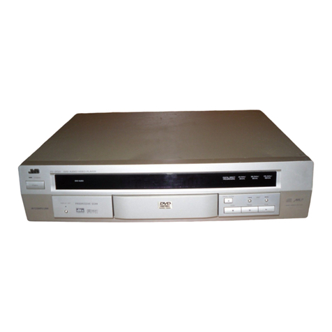
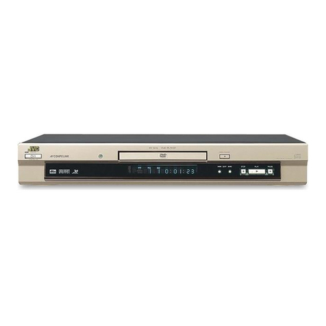
JVC XV-DDV1SL User manual

SERVICE MANUAL
COPYRIGHT © 2003 VICTOR COMPANY OF JAPAN, LIMITED No.XA010
2003/9
HDD RECORDER / DVD PLAYER
XA01020037XV-DDV1SL
TABLE OF CONTENTS
1 PRECAUTION. . . . . . . . . . . . . . . . . . . . . . . . . . . . . . . . . . . . . . . . . . . . . . . . . . . . . . . . . . . . . . . . . . . . . . . . . 1-3
2 SPECIFIC SERVICE INSTRUCTIONS. . . . . . . . . . . . . . . . . . . . . . . . . . . . . . . . . . . . . . . . . . . . . . . . . . . . . . 1-8
3 DISASSEMBLY . . . . . . . . . . . . . . . . . . . . . . . . . . . . . . . . . . . . . . . . . . . . . . . . . . . . . . . . . . . . . . . . . . . . . . . 1-9
4 ADJUSTMENT . . . . . . . . . . . . . . . . . . . . . . . . . . . . . . . . . . . . . . . . . . . . . . . . . . . . . . . . . . . . . . . . . . . . . . . 1-18
5 TROUBLE SHOOTING. . . . . . . . . . . . . . . . . . . . . . . . . . . . . . . . . . . . . . . . . . . . . . . . . . . . . . . . . . . . . . . . . 1-24
ENTER
VIDEO
ENTER
CHANNEL
TOP MENU / HDD NAVI
MENU / HDD PROG.
+
-
DVD / HDDHDD
DVD
PROGRESSIVE
Area Suffix
B ---------------------------- U.K.
ED ------- The Netherlands

1-2 (No.XA010)
SPECIFICATION
Specifications and appearance are subject to change without prior notice.
Digital output signal chart
HDD Deck-Video/Audio Video format MPEG2 (VBR)
Audio format MPEG1 Layer2
Maximum recording time (approx.) (SP): 20 hours
(LP): 28 hours
(EP): 56 hours
(SEP): 80 hours
DVD player-Audio Total harmonic distortion:Less than 0.006%
Dynamic range 16 bits: 98 dB
20 bits: 100 dB
24 bits: 100 dB
Frequency range CD (fs=44.1 kHz): 2 Hz to 20,000 Hz
DVD (fs=48 kHz): 2 Hz to 22,000 Hz
DVD (fs=96 kHz): 2 Hz to 44,000 Hz
Output level DVD/HDD AUDIO OUT 2 Vrms (10 kΩ)
DVD DIGITAL OUT COAXIAL 0.5Vp-p (75Ωtermination)
OPTICAL -21dBm to -15dBm(Peak)
DVD player-Video Horizontal resolution 500 lines
Output level RGB 0 - 700 mV (75Ω)
S-video (Y) 1.0 Vp-p (75Ω)
(C) 300 mV (75Ω)
Composite video 1.0 Vp-p (75Ω)
Tuner/Timer TV channel storage capacity 99 positions (+AUX position)
Tuning system Frequency synthesized tuner
Channel coverage VHF 44.5 MHz - 143 MHz/
143 MHz - 470 MHz
UHF 470 MHz - 862 MHz
Memory backup time Approx. 10 min.
General Power requirement AC 230 V, 50 Hz
Power consumption Power on: 45 W
Power off: 15 W
Operating position Horizontal only
Dimensions (WxHxD) 435 mm ×68 mm ×346 mm
Weight 5.3 kg
Accessories RF cable: ×1
Audio/video cable: ×1
Satellite Controller: ×1
Remote control unit: ×1
Battery-R6P(SUM-3)/AA(15F): ×2
Disc type Output
PCM ONLY DOLBY DIGITAL/PCM STREAM/PCM
DVD with 48 kHz, 16/20/24 bit linear PCM 48 kHz, 16 bit, stereo linear PCM
DVD with 96 kHz, 16/20/24 bit linear PCM 48kHz, 16 bit, stereo linear PCM (Down sampling)
DVD with DTS 48 kHz, 16 bit, stereo linear PCM DTS bitstream
DVD with Dolby Digital 48 kHz, 16 bit, stereo linear PCM Dolby Digital bitstream
DVD with MPEG Multichannel 48 kHz, 16 bit, stereo linear PCM MPEG bitstream
SVCD/Video CD/Audio CD 44.1 kHz, 16 bit, stereo linear PCM
Audio CD with DTS 44.1 kHz, 16 bit, stereo linear PCM DTS bitstream
CD-R/RW with MP3 Linear PCM

(No.XA010)1-3
SECTION 1
PRECAUTION
1.1 Safety Precautions
(1) This design of this product contains special hardware and
many circuits and components specially for safety purpos-
es. For continued protection, no changes should be made
to the original design unless authorized in writing by the
manufacturer. Replacement parts must be identical to
those used in the original circuits. Services should be per-
formed by qualified personnel only.
(2) Alterations of the design or circuitry of the product should
not be made. Any design alterations of the product should
not be made. Any design alterations or additions will void
the manufacturers warranty and will further relieve the
manufacture of responsibility for personal injury or property
damage resulting therefrom.
(3) Many electrical and mechanical parts in the products have
special safety-related characteristics. These characteris-
tics are often not evident from visual inspection nor can the
protection afforded by them necessarily be obtained by us-
ing replacement components rated for higher voltage, watt-
age, etc. Replacement parts which have these special
safety characteristics are identified in the Parts List of Ser-
vice Manual. Electrical components having such features
are identified by shading on the schematics and by ( ) on
the Parts List in the Service Manual. The use of a substitute
replacement which does not have the same safety charac-
teristics as the recommended replacement parts shown in
the Parts List of Service Manual may create shock, fire, or
other hazards.
(4) The leads in the products are routed and dressed with ties,
clamps, tubings, barriers and the like to be separated from
live parts, high temperature parts, moving parts and/or
sharp edges for the prevention of electric shock and fire
hazard. When service is required, the original lead routing
and dress should be observed, and it should be confirmed
that they have been returned to normal, after reassem-
bling.
(5) Leakage shock hazard testing)
After reassembling the product, always perform an isola-
tion check on the exposed metal parts of the product (an-
tenna terminals, knobs, metal cabinet, screw heads,
headphone jack, control shafts, etc.) to be sure the product
is safe to operate without danger of electrical shock.Do not
use a line isolation transformer during this check.
• Plug the AC line cord directly into the AC outlet. Using a
"Leakage Current Tester", measure the leakage current
from each exposed metal parts of the cabinet, particular-
ly any exposed metal part having a return path to the
chassis, to a known good earth ground. Any leakage cur-
rent must not exceed 0.5mA AC (r.m.s.).
• Alternate check method
Plug the AC line cord directly into the AC outlet. Use an
AC voltmeter having, 1,000 ohms per volt or more sensi-
tivity in the following manner. Connect a 1,500 ohm 10W
resistor paralleled by a 0.15 F AC-type capacitor be-
tween an exposed metal part and a known good earth
ground.
Measure the AC voltage across the resistor with the AC
voltmeter.
Move the resistor connection to each exposed metal
part, particularly any exposed metal part having a return
path to the chassis, and measure the AC voltage across
the resistor. Now, reverse the plug in the AC outlet and
repeat each measurement. Voltage measured any must
not exceed 0.75 V AC (r.m.s.). This corresponds to 0.5
mA AC (r.m.s.).
1.2 Warning
(1) This equipment has been designed and manufactured to
meet international safety standards.
(2) It is the legal responsibility of the repairer to ensure that
these safety standards are maintained.
(3) Repairs must be made in accordance with the relevant
safety standards.
(4) It is essential that safety critical components are replaced
by approved parts.
(5) If mains voltage selector is provided, check setting for local
voltage.
1.3 Caution
Burrs formed during molding may be left over on some parts
of the chassis.
Therefore, pay attention to such burrs in the case of pre-
forming repair of this system.
1.4 Critical parts for safety
In regard with component parts appearing on the silk-screen
printed side (parts side) of the PWB diagrams, the parts that are
printed over with black such as the resistor ( ), diode ( )
and ICP ( ) or identified by the " " mark nearby are critical for
safety. When replacing them, be sure to use the parts of the
same type and rating as specified by the manufacturer. (Except
the JC version)
1-4 (No.XA010)
1.5 Preventing static electricity
Electrostatic discharge (ESD), which occurs when static electricity stored in the body, fabric, etc. is discharged, can destroy the laser
diode in the traverse unit (optical pickup). Take care to prevent this when performing repairs.
1.5.1 Grounding to prevent damage by static electricity
Static electricity in the work area can destroy the optical pickup (laser diode) in devices such as DVD players.
Be careful to use proper grounding in the area where repairs are being performed.
(1) Ground the workbench
Ground the workbench by laying conductive material (such as a conductive sheet) or an iron plate over it before placing the
traverse unit (optical pickup) on it.
(2) Ground yourself
Use an anti-static wrist strap to release any static electricity built up in your body.
(3) Handling the optical pickup
• In order to maintain quality during transport and before installation, both sides of the laser diode on the replacement optical
pickup are shorted. After replacement, return the shorted parts to their original condition.
(Refer to the text.)
• Do not use a tester to check the condition of the laser diode in the optical pickup. The tester's internal power source can easily
destroy the laser diode.
1.6 Handling the traverse unit (optical pickup)
(1) Do not subject the traverse unit (optical pickup) to strong shocks, as it is a sensitive, complex unit.
(2) Cut off the shorted part of the flexible cable using nippers, etc. after replacing the optical pickup. For specific details, refer to the
replacement procedure in the text. Remove the anti-static pin when replacing the traverse unit. Be careful not to take too long
a time when attaching it to the connector.
(3) Handle the flexible cable carefully as it may break when subjected to strong force.
(4) I t is not possible to adjust the semi-fixed resistor that adjusts the laser power. Do not turn it.

(No.XA010)1-5
1.7 Important for laser products
(1) CLASS 1 LASER PRODUCT
(2) DANGER : Invisible laser radiation when open and inter
lock failed or defeated. Avoid direct exposure to beam.
(3) CAUTION : There are no serviceable parts inside the
Laser Unit. Do not disassemble the Laser Unit. Replace the
complete Laser Unit if it malfunctions.
(4) CAUTION : The compact disc player uses invisible laser
radiation and is equipped with safety switches which
prevent emission of radiation when the drawer is open and
the safety interlocks have failed or are de feated.
It is dangerous to defeat the safety switches.
(5) CAUTION : If safety switches malfunction, the laser is able
to function.
(6) CAUTION : Use of controls, adjustments or performance of
procedures other than those specified herein may result in
hazardous radiation exposure.
CAUTION
Please use enough caution not to see the beam directly
or touch it in case of anadjustment or operation check.
VARNING
Osynlig laserstrålning är denna del är öppnad och spårren är
urkopplad. Betrakta ej strålen.
VARO
Avattaessa ja suojalukitus ohitettaessa olet alttiina näkymät-
tömälle lasersäteilylle. Älä katso säteeseen.
ADVARSEL
Usynlig laserstråling ved åbning, når sikkerhedsafbrydere er
ude af funktion. Undgå udsasttelse for stråling.
ADVARSEL
Usynlig laserstråling ved åpning, når sikkerhetsbryteren er avs-
lott. unngå utsettelse for stråling.
REPRODUCTION AND POSITION OF LABEL
WARNING LABEL
On the mechanism cover

1-6 (No.XA010)
1.8 Precautions for Service
1.8.1 Handling of Traverse Unit and Laser Pickup
(1) Do not touch any peripheral element of the pickup or the actuator.
(2) The traverse unit and the pickup are precision devices and therefore must not be subjected to strong shock.
(3) Do not use a tester to examine the laser diode. (The diode can easily be destroyed by the internal power supply of the tester.)
(4) To replace the traverse unit, pull out the metal short pin for protection from charging.
(5) When replacing the pickup, after mounting a new pickup, remove the solder on the short land which is provided at the center of
the flexible wire to open the circuit.
(6) Half-fixed resistors for laser power adjustment are adjusted in pairs at shipment to match the characteristics of the optical block.
Do not change the setting of these half-fixed resistors for laser power adjustment.
1.8.2 Destruction of Traverse Unit and Laser Pickup by Static Electricity
Laser diodes are easily destroyed by static electricity charged on clothingor the human body. Before repairing peripheral elements of
the traverse unit or pickup, be sure to take the following electrostatic protection:
(1) Wear an antistatic wrist wrap.
(2) With a conductive sheet or a steel plate on the workbench on which the traverse unit or the pick up is to be repaired, ground the
sheet or the plate.
(3) After removing the flexible wire from the connector (CN101), short-circuit the flexible wire by the metal clip.
(4) Short-circuit the laser diode by soldering the land which is provided at the center of the flexible wire for the pickup.
After completing the repair, remove the solder to open the circuit.
Short circuit
CN101
DVD Servo control board
Flexible wire
CN202
CN201
DVD Mechanism

(No.XA010)1-7
1.9 Hard Disk Drive (HDD) Handling Precautions
The HDD is a precision device for use in reading and writing a large amount of data on or from a disk rotating at a high speed. If it is
not handled carefully, either abnormal operation may result or it may not be possible to read data. The HDD is sensitive to the following
items and special care is required in safeguarding against them when handling an HDD. Also take care in handling a set incorporating
an HDD.
(1) Vibrations and impacts
(2) Static electricity
(3) Rough handling
1.9.1 Handling in transport, etc.
• Be sure to place the HDD in the manufacturer's specified pack-
age carton before transport.
• When receiving a package containing an HDD, check that the
package carton is not damaged (such as having holes in the
carton, crushed corners, etc.).
• Do not impact the packaging carton when loading or unloading
it.
• It is not permitted to use the inner package carton only for
transporting an HDD.
• Do not stack package cartons one upon another.
1.9.2 Handling an HDD in the stand-alone status
• When handling an HDD on a hard workbench, place an anti-
static mat (rubber sheet) or similar object on the hard surface
(to prevent any impacts occurring between the HDD and
bench).
• Do not stack the HDDs one upon another.
• Do not knock an HDD with a hard object (such as a screwdriv-
er).
• Do not place an HDD on its side panel without using a support
(do not place an HDD in an unstable position).
1.9.3 Handling the installation of an HDD
• Place antistatic mats or similar sheets on all of the surfaces on which work is conducted or when the HDD is transported.
• Do not permit the HDD to knock against the set's brackets.
• When screwing the brackets, be careful not to knock the HDD. When using a power screwdriver, use a low-shock model and arrange
the tightening torque properly.
• When mounting an HDD in a main body, take care not to apply excessive force to the brackets.
HDD
Do not throw or
drop packages.
Be sure to package and
transport the HDDs correctly.

1-8 (No.XA010)
SECTION 2
SPECIFIC SERVICE INSTRUCTIONS
This service manual does not describe SPECIFIC SERVICE INSTRUCTIONS.

(No.XA010)1-9
SECTION 3
DISASSEMBLY
3.1 Main body section
3.1.1 Removing the top cover (See Figure 1)
(1) Remove the four screws Aattaching the top cover on both
sides of the main unit.
(2) Remove the three screws Battaching the top cover on the
rear side of the main unit.
(3) Slide the top cover approx.10mm in the rear direction.
Open the right side slightly, and lift the top cover to remove
it.
Note:
Sliding the top cover in the rear direction may damage the in-
ternal wires. Fig.1
3.1.2 Removing the front panel assembly (See Figure 2, Figure 3)
• Prior to the following procedure, remove the top cover.
(1) Disconnect the card wire from each connector CN41,
CN42, and CN43 on the main board.
(2) Disconnect the card wire from the connector CN702 on
SCART terminal board.
(3) Remove one screw Cattaching the DVD mechanism cover
and the lug wire.
(4) Remove the three screws Dand two screws Eattaching
the front panel assembly on the bottom side of the main
body.
(5) Remove one hook a, and remove the front panel assembly
in the front direction.
Fig.2
Fig.3
B
B
B
Ax 2
Ax 2
TOP COVER
TOP COVER
TOP COVER
Main board
SCART terminal board Front panel assembly
CN42
CN41
CN43CN702
C
Front panel assembly
E
E
Hook a
Hook a
Hook a
D
D
D
D
D
D
D
D
D

1-10 (No.XA010)
3.1.3 Removing the hard disc (See Figure 4, Figure 5)
• Prior to the following procedure, remove the top cover and the
front panel assembly.
(1) Disconnect the card wire on each connector CN602 and
CN603 on the hard disc control board.
(2) Disconnect the socket wire from each connector CN93 and
CN94 on the power supply board.
(3) Remove the four screws Fattaching the hard disc control
board.
(4) Remove the power cord and IDE cable connected to the
hard disc.
(5) Remove the four screws Gattaching the hard disc bracket.
(6) Remove the four screws Hattaching the hard disc.
Fig.4
Fig.5
Hard disc control board
Power supply board
F
F
F
CN93
CN94
F
CN602
CN603
CN602
CN603
Hard disc
Hard disc control board
IDE cable
Power cord
G
H
G
H
H
H
G
G
H
H
G
G

(No.XA010)1-11
3.1.4 Removing the DVD mechanism assembly (See Figure 6, Figure 7, Figure 8)
• Prior to the following procedure, remove the top cover, the
front panel assembly, and the hard disc control board.
(1) Remove the three screws Iattaching the DVD mechanism
cover.
(2) The three connectors on the DVD servo control board are
directly connected to the connectors on the main board.
While lifting the rear part of the DVD mechanism assembly,
disconnect the connector from each connector CN801,
CN513, and CN614 on the main board.
(3) Turn the DVD mechanism assembly upside down, and re-
move the three screws J. Then, remove the DVD mecha-
nism cover.
Fig.6
Fig.7
Fig.8
I
DVD Mechanism cover II
Main board
DVD Mechanism assembly
DVD Servo control board
CN513CN801 CN614
JDVD Mechanism assembly J
J
DVD Mechanism
cover

1-12 (No.XA010)
3.1.5 Removing the power supply board (See Figure 9)
• Prior to the following procedure, remove the top cover, the
front panel assembly, and the hard disc.
(1) Disconnect the card wire from the connector CN95 on the
power supply board.
(2) Disconnect the power cord from the socket CN91 on the
power supply board.
(3) Disconnect the 2-pin wire from the connector CN92 on the
power supply board.
(4) Remove the four screws Kattaching the power board.
Fig.9
3.1.6 Removing the SCART terminal board (See Figure 10)
• Prior to the following procedure, remove the top cover.
(1) Disconnect the card wire from each connector CN701,
CN702, CN902, CN903, and CN904 on the SCART termi-
nal board.
(2) Remove the two screws Iand M attaching the lug wire.
(3) Remove the two screws Lattaching the SCART terminal
board.
(4) Remove the two fasteners.
Fig.10
3.1.7 Removing the main board (See Figure 11)
• Prior to the following procedure, remove the top cover, the
front panel assembly, the hard disc, the DVD mechanism as-
sembly, the power board, and the SCART terminal board.
(1) Remove the four screws Mattaching the main board.
(2) Remove the seven screws Nattaching the main board on
the rear side.
Fig.11
CN91
Power supply board
K
K
K
CN95CN92 K
CN902CN904
I
K
CN702CN903CN701
L L
Fastener
SCART terminal board
M
MMM M
N
Main board

(No.XA010)1-13
3.2 DVD mechanism assembly
3.2.1 Removing the DVD servo control board
(See Figure 1)
Caution:
Be sure to solder the short land sections "a" on the flexible wire
before disconnecting the flexible wire from connector CN101
on the DVD servo control board.
If the flexible wire is disconnected without attaching solder, the
pickup unit may be destroyed by static electricity.
(1) From the back side of the DVD mechanism assembly, at-
tach solder to the short land sections "a" of the flexible wire
that is connected to the connector CN101 of the DVD servo
control board.
(2) Disconnect the flexible wire from connector CN101 on the
DVD servo control board.
(3) Disconnect the card wires from connectors CN201 and
CN202 on the DVD servo control board.
(4) Remove the two screws Aattaching the DVD servo control
board.
(5) While pushing the claw "b" of the DVD mechanism assem-
bly in the direction of the arrow, remove the DVD servo
control board from the projections "c" and "d" in an upward
direction.
Caution:
In the assembly, be sure to remove solder from the short land
sections "a" after connecting the flexible wire.
Fig.1
3.2.2 Removing the DVD traverse mechanism assembly
(See Figure 2)
• Remove the DVD servo control board.
(1) Remove the two screws Battaching the DVD traverse
mechanism assembly.
(2) Disengage the claw eattaching the DVD traverse mecha-
nism assembly and then take out the DVD traverse mech-
anism assembly.
Fig.2
Short land sections a
CN101
DVD servo
control board
Flexible wire CN202
CN201
Projection d
Projection c
Claw b
A
A K
DVD mechanism assembly
Claw e
DVD traverse mechanism assembly
B B

1-14 (No.XA010)
3.2.3 Removing the DVD pickup unit
(See Figure 3, Figure 4, Figure 5)
• Remove the DVD servo control board.
• Remove the DVD traverse mechanism assembly.
(1) From the top side of the DVD traverse mechanism assem-
bly, remove the screw Cattaching the bracket.
(2) Remove the claw fattaching the thrust spring and then
take out the thrust spring.
(3) Remove the lead screw from the section gand then re-
move the shaft 1 from the section h.
(4) Disengage the section iof the DVD pickup unit and then re-
move the DVD pickup unit with the shaft 1.
(5) Pull the shaft 1 out of the DVD pickup unit.
(6) Remove the two screws Dattaching the SW. actuator.
Fig.3
Fig.4
Fig.5
DVD traverse mechanism assembly
Bracket DVD pickup unit
Shaft 1
C
Section h
Section g
Section i
Claw f
DVD pickup unit
Shaft 2 Shaft 1
Thrust spring
Lead scre
w
Shaft 1 DVD pickup uni
t
D
SW. actuator

(No.XA010)1-15
3.2.4 Attaching the DVD pickup unit
(See Figure 3, Figure 4, Figure 5, Figure 6, Figure 7)
Reference:
Refer to the explanation of "Removing the DVD pickup unit" on
the preceding page.
(1) Attach the SW. actuator and shaft 1 to the DVD pickup unit.
(See Figure 5)
(2) Engage the section iof the DVD pickup unit to the shaft 2
of the DVD traverse mechanism assembly first, and set the
both ends of the shaft 1 of the DVD pickup unit in the sec-
tions hand h' of the DVD traverse mechanism assembly.
(3) Slide the DVD pickup unit all the way in the direction of the
arrow.
(4) Mesh the lead screw to the section jof DVD pickup unit and
then set the end of the lead screw to the section g.
(5) Attach the thrust spring. (See Figure 4)
(6) Attach the bracket. (See Figure 3)
Fig.6
Fig.7
3.2.5 Removing the spindle motor board
(See Figure 8, Figure 9)
• Remove the DVD servo control board.
• Remove the DVD traverse mechanism assembly.
(1) From the top side of the DVD traverse mechanism assem-
bly, remove the feed motor wire that is soldered to the spin-
dle motor board.
(2) From the back side of the DVD traverse mechanism as-
sembly, remove the three screws Eattaching the spindle
motor board.
Fig.8
Fig.9
Section i
Section h
Section h'
Shaft 2
Shaft 1
DVD pickup unit
DVD pickup unit
Section g
Section j
Lead scre
w
Spindle motor
board
Feed moto
r
wire
Feed motor
Remove the solders.
EE
Spindle moto
r
board

1-16 (No.XA010)
3.2.6 Removing the feed motor
(See Figure 10, Figure 11, Figure 12)
• Remove the DVD servo control board.
• Remove the DVD traverse mechanism assembly.
(1) Remove the four screws Fattaching the traverse mecha-
nism assembly.
(2) Take out the traverse mechanism assembly from the
mechanism base.
(3) Remove the screw Cattaching the bracket and take out the
bracket.
(4) Disengage the claw fattaching the thrust spring and take
out the thrust spring.
(5) Pull out the lead screw in the direction of the arrow.
(6) Remove the feed gear M.
(7) Remove the feed motor wire that is soldered to the spindle
motor board.
(8) Remove the two screws Gattaching the feed motor and
take out the feed motor.
Fig.10
Fig.11
Fig.12
Traverse
mechanism
assembly
Feed moto
r
Bracket
F F
F
C
Mechanism
base
Spindle motor board
Feed motor
Feed gear M
Remove the solders.
Claw f
Feed motor wire
Lead screw
Thrust spring
G
Traverse
mechanism assembly

(No.XA010)1-17
3.2.7 Removing the switch board
(See Figure 13)
• Remove the DVD mechanism assembly.
(1) From the top side of the DVD mechanism assembly, re-
move the screw Hattaching the switch board.
(2) Lift the switch board slightly and then remove the wire from
connector CN101 on the switch board.
3.2.8 Removing the loading motor assembly
(See Figure 1, Figure 13, Figure 14, Figure 15)
• Remove the DVD mechanism assembly.
(1) From the back side of the DVD mechanism assembly, dis-
connect the card wire from connector CN202 on the DVD
servo control board. (See Figure 1)
(2) From the top side of the DVD mechanism assembly, re-
move the two screws Iattaching the clamper base assem-
bly.
(3) Disconnect the wire from connector CN101 on the switch
board while lifting the clamper base assembly slightly and
remove the clamper base assembly.
(4) Remove the screw Kattaching the roller holder assembly.
(See Figure 1)
(5) Remove the three screws Jattaching the roller holder as-
sembly and take out the roller holder assembly.
(6) Disconnect the wires from connectors CN103 and CN104
on the loading motor assembly.
(7) Remove the belt of the loading motor assembly.
(8) Remove the two screws L attaching the loading motor as-
sembly and take out the loading motor assembly.
Fig.13
Fig.14
Fig.15
DVD mechanism assembly Clamper base assembl
y
Switch board
CN101
H
I I
Roller holde
r
assembly
J
J
Belt
Loading motor assembl
y
CN103 CN104
LL
Roller holder
assembly

1-18 (No.XA010)
SECTION 4
ADJUSTMENT
4.1 Test mode setting method
(1) Plug the power plug, and A power supply key is pushed and a power supply is turned ON.
(2) The "DVD / HDD" key of a main body is pushed and it is made DVD mode. (DVD indicator lighting state)
(3) Press the "Record" key, the "Stop" key and the "Play" key of the main body simultaneously.
(4) The FL display shows "∗0", and the main body turns to test mode. "∗" means the destination, and "0" means parameter adjust-
ment status.
(5) To release test mode, press "POWER" key of the main body.
NOTE:
Each pressing of "SET UP" key of the remote controller in test mode changes the mode as follows.
4.2 Method of displaying version of firmware
(1) Set the main body at test mode.
(2) Press "SET UP" key of the remote controller once. Then, version number and alphabetical letter are displayed in the FL display
as follows:
4.3 Initialization method
Please initialize according to the following procedures in the following case:
• Just after you upgrade the firmware.
• After you confirm the symptoms that a customer points out. First Initialize, and then confirm whether the symptoms are improved or
not.
• After servicing, before returning the main body to a customer. (Initialized main body should be returned to a customer.)
(1) Set the main body at test mode.
(2) Press "TOP MENU / HDD NAVIGATION" key of the main body.
(3) When initialization is completed, the FL display changes from "∗0" to "∗00".(The left "0" of "00" is not always "0". It shows pa-
rameter adjustment status.)
Becames test mode
Version of firmware
Check mode
Not used
0 ------------------------------
_ _ --------------
FL Display becames all lighting
CHECK -------------------------
EXPERT -----------------------
Backend
System controller 3 3 0 0 0 2
FL Display (Example)
ENTER
SET UP key
(Change of mode)
POWER key
DVD/HDD key
FL Display
PLAY key
(for test mode)
TOP MENU/HDD NAVIGATION key
(for initialize)
STOP key
(for test mode)
RECORD key
(for test mode)

(No.XA010)1-19
4.4 All-initialization method
Please perform all-initialization according to the following procedures in the following case:
• Just after you exchange the pick-up.
• Just after you exchange the spindle motor.
• Just after you exchange the traverse mechanism base.
NOTE:
Please perform all-initialization when you exchange the parts above and also when you remove the parts above.
• Just after the flap adjustment of the pick-up guide shaft
(1) Set the main body at test mode.
(2) Press and hold "MENU / HDD PROGRAMME" key of the main body for more than 2 seconds.
(3) When all-initialization is completed, the FL display changes from "∗0" to "∗33".
NOTE:
After all-initialization, be sure to perform optimization adjustment of Front End parameter.
4.5 Optimization adjustment of Front End parameter
Adjustment to optimize Front End parameter must be performed in each mechanism assembly of this model for high-speed start-
ing.Please perform optimization according to the following procedures just after all-initialization is completed and when FL display
shows anything except "∗0" (For example when FL display shows "∗1", "∗2", and "∗3") at test mode.
(1) Press "POWER" key of the main body to turn the main body ON (not to set the main body at test mode).
(2) Insert the test disc VT-501 or commercial dual-layer DVD software.
(3) Remove the disc when the FL display changes from "READING" to disc information.
(4) Perform the same procedures as in (2) and (3) above by using the test disc CTS-1000 or commercial CD-DA software.
(5) Set the main body at test mode, and check that the FL display shows "∗0".
NOTE:
Status of this adjustment can be judged by the number displayed at test mode as follows:
NOTE:
As for a disc used for adjustment,
• Disc should be mounted. ("Mounting" means to display "READING" after the disc is inserted and then display the disc infor-
mation.) Disc need not be played.
• If you do not have test disc either VT-501 (DVD) or CTS-1000 (CD-DA), use a commercial disc (for DVD, dual-layer soft-
ware) after seeing and checking that the disc is neither curved nor foreseen that it may shake at the time of playback.If you
use a disc with bad features, starting time may be slow or disc may not be read.
DVD adjustment CD adjustment FL display at test mode
Adjusted Adjusted ∗0
Not adjusted Adjusted ∗1
Adjusted Not adjusted ∗2
Not adjusted Not adjusted ∗3
ENTER
POWER key
DVD/HDD key
FL Display
PLAY key
(for test mode)
MENU/HDD PROGRAMME key
(for all-initialize : It pushes 2 seconds or more.)
STOP key
(for test mode)
RECORD key
(for test mode)

1-20 (No.XA010)
4.6 Display of current value of laser
(1) Set the main body at test mode.
(2) Press "SET UP" key of the remote controller three times. Then, FL display is displayed "CHECK".
(3) The laser current value can be switched between the value of CD and that of DVD by pressing the following key of the remote
controller.
The number shown in the FL display shows mA of current value of laser.
The first two numbers ("25" in "2530") shows current value of laser at the time of adjustment after the latest all-initialization, 25mA
in this example.
The last two numbers ("30" in "2530") shows the present current value of laser, 30mA in this example.
The first two numbers ("25" in "2530") usually shows current value of laser at the time of shipment, so you can see how the prod-
uct has been deteriorated by comparing the first two numbers ("25" in "2530") and the last two numbers ("30" in "2530").
CD:
The laser current value of 49 mA or less is normal.The laser current value of over 50 mA is not normal. Laser diode of the
pickup has been deteriorated.
DVD:
The laser current value of 64 mA or less is normal.The laser current value of over 65 mA is not normal. Laser diode of the
pickup has been deteriorated.
To return to test mode, press "STOP" key of the main body.
4.7 Flap adjustment of the pick-up guide shaft
Please perform flap adjustment of the pick-up guide shaft in the following case:
• Just after you exchange the pick-up.
• Just after you exchange the spindle motor.
• Just after you exchange the traverse mechanism base.
NOTE:
Please perform flap adjustment of the pick-up guide shaft when you exchange the parts above and also when you remove the
parts above.
• When the reading accuracy of the signal is bad (There is a block noise in the screen, Screen stops in the outer circumference of a
disc, etc.)
2 5 3 0 0 0 0 0
FL Display (Example)
Remote controller "4" key --- Laser of CD
Remote controller "5" key --- Laser of DVD
ENTER
POWER key
DVD/HDD key
FL Display
PLAY key
(for test mode)
STOP key
(for test mode)
RECORD key
(for test mode)
SET UP key
(change of mode)
4 key
(laser of CD)
5 key
(laser of DVD)
6 key
(display of jitter value)
1 key
(auto adjustment)
Table of contents
Other JVC DVD Player manuals