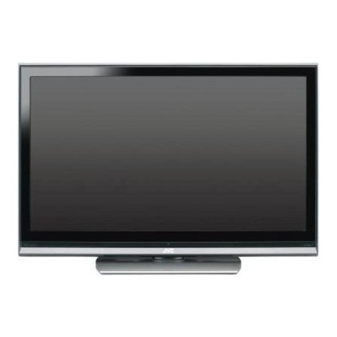
JVC AV-15LCG User manual

1R
0DU
$
9/&*
$
9/&+
$
9/&6
&23<5,*+79,&725&203$1<2)-$3$1/7'
$9/&*
$9/&*$
$9/&+
$9/&6
&217(176
T63(&,),&$7,216]]]]]]]]]]]]]]]]]]]]]]]]]]]]]]]] ]]]]]]]]]]]]]]]]]]]]]]]]]]]]]]]] ]]
T0$,1',))(5(1&(/,67 ]]]]]]]]]]]]]]]]]]]]]]]]]]]]]]]] ]]]]]]]]]]]]]]]]]]]]]]]]]]]
T6$)(7<35(&$ 7,216]]]]]]]]]]]]]]]]]]]]]]]]]]]]]]]] ]]]]]]]]]]]]]]]]]]]]]]]]]]]]
T63(&,),&6(59,&(,1675 &7,216 ]]]]]]]]]]]]]]]]]]]]]]]]]]]]]]]] ]]]]]]]]]]]]]]]]]
T) 1&7,216]]]]]]]]]]]]]]]]]]]]]]]]]]]]]]]] ]]]]]]]]]]]]]]]]]]]]]]]]]]]]]]]] ]]]]]]]
T7(&+1,&$/,1)250$7,21]]]]]]]]]]]]]]]]]]]]]]]]]]]]]]]] ]]]]]]]]]]]]]]]]]]]]]]]]
T6(59,&($'- 670(176 ]]]]]]]]]]]]]]]]]]]]]]]]]]]]]]]] ]]]]]]]]]]]]]]]]]]]]]]]]]
T752 %/(6+227,1* ]]]]]]]]]]]]]]]]]]]]]]]]]]]]]]]] ]]]]]]]]]]]]]]]]]]]]]]]]]]]]]
T3$576/,67]]]]]]]]]]]]]]]]]]]]]]]]]]]]]]]] ]]]]]]]]]]]]]]]]]]]]]]]]]]]]]]]] ]]]]]]
à
67$1'$5'&,5& ,7',$*5$0$33(1'(' ]]]]]]]]]]]]]]]]]]]]]]]]]]]]]]]] ]]]]]]
6(59,&(0$1 $/
/&'7(/(9,6,21

1R
$
9/&*
$
9/&+
$
9/&6
63(&,),&$7,216
,WHPV &RQWHQWV
'LPHQVLRQV:G+G' FPuFPuFP
0DVV NJ :LWKRXW'H NWRS WDQG
795)%URDGFDVWLQ 6\VWHP
&RORUV\VWHP
%*'.,0
3$/6(&$0176&
795HFHLYLQ &KDQQHOVDQG)UHTXHQF\
3UR UDP6HOHFWLRQ&KDQQHO
9+)(¤(
8+)(¤(
&$796¤6
+<3(5EDQG6–6
&KDQQHO
0XOWLVRXQG6\VWHP 1,&$0>8. \ WHP@
$>*HUPDQ\ \ WHP@
7HOHWH[W6\VWHP )/2))D WH[W >$9/&6RQO\@
723 >$9/&6RQO\@
3RZHU,QSXW $&9–9+]+] $&DGDSWRULQSXW
'&9$ /&'WHOHYL LRQLQSXW
3RZHU&RQVXPSWLRQ 0D[LPXP:RSHUDWLQJ
6WDQGE\:DW$&9
/&'3DQHO 3L[HOSLWFKPP+uPP9 5*% WULSH
6FUHHQ6L]H LQFK9L LEOHDUHDFP>PHD XUHGGLDJRQDOO\@ $ SHFWUDWLR
6SHDNHU :2YDOW\SHu
$XGLR3RZHU2XWSXW ::UDWHG
$QWHQQD,QSXW7HUPLQDO :XQEDODQFHGDHULDOW\SHFRQQHFWRUu
,QSXW7HUPLQDO
$9
6$9
'9'
3&
9,'(25&$SLQMDFNu
$8',2/55&$SLQMDFNu
0LQL',1SLQFRQQHFWRUu >6YLGHR<&LQSXW@
<3%355&$SLQMDFNu >&RPSRQHQW LJQDOLLQSXW@
' XESLQURZ >9*$69*$;*$LQSXW@
+HDGSKRQH2XWSXW PPPLQLMDFN WHUHRW\SH
5HPRWH&RQWURO8QLW /*9'50&! 'U\FHOOEDWWHU\$$580u
/*9(50&! 'U\FHOOEDWWHU\$$580u >$9/&6RQO\@
Design & specification are subject to change without notice.
0$,1'())(5(1&(/,67
,WHP $9/&6 $9/&+ $9/&* $9/&*$ 5HPDUNV
0(025<,&>,&@ /*,$/%6
ZLWK7HOHWH[W
/*,$/%+
QR7HOHWH[W
/*,$/%
QR7HOHWH[W
/*,$/%
QR7HOHWH[W 2QWKH0$,13:%$66©<
5(027(&21752/81,7 /*9(
50&!
/*9'
50&!
/*9'
50&!
/*9'
50&! $FFH DU\
32:(5&25' /*9(+$
URXQGW\SHSLQ
/*9%+$
8.W\SHSLQ
/*9(+$
URXQGW\SHSLQ
/*98+$
IODWW\SHSLQ $FFH DU\
,16758&7,21%22. /*9$9
(QJOL K&KLQH H
/*9$9
(QJOL K&KLQH H
/*9$:
(QJOL K)UHQFK$UDELF
/*9$7
(QJOL K $FFH DU\
3$&.,1*&$6( /*9% /*9$ /*9& /*9'

No.51932 3
AV-15LCG
AV-15LCH
AV-15LCS
SAFETY PRECAUTIONS
Many electrical and mechanical parts in this chassis have special safety-related characteristics.These parts are identified by in
the Schematic Diagram and Replacement Parts List.
It is essential that these special safety parts should be replaced with the same components as recommended in this manual to
prevent X-RADIATION, Shock, Fire, or other Hazards.
Do not modify the original design without permission of manufacturer.
General Guidance
An lsolationTransformer should always be used during
the servicing of a receiver whose chassis is not isolated from
the AC power line.Use a transformer of adequate power rating
as this protects the technician from accidents resulting in
personal injury from electrical shocks.
It will also protect the receiver and it's components from being
damaged by accidental shorts of the circuitary that may be
inadvertently introduced during the service operation.
If any fuse (or Fusible Resistor) in this TV receiver is blown,
replace it with the specified.
When replacing a high wattage resistor (Oxide Metal Film
Resistor, over 1W), keep the resistor 10mm away from PCB.
Keep wires away from high voltage or high temperature parts.
Due to high vacuum and large surface area of picture tube,
extreme care should be used in handling the PictureTube.
Do not lift the Picture tube by it's Neck.
X-RAY Radiation
Warning:
To determine the presence of high voltage, use an accurate
high impedance HV meter.
Adjust brightness, color, contrast controls to minimum.
Measure the high voltage.
The meter reading should indicate
23.5±1.5KV: 14-19 inch, 26±1.5KV: 19-21 inch,
29.0±1.5KV: 25-29 inch, 30.0±1.5KV: 32 inch
If the meter indication is out of tolerance, immediate service
and correction is required to prevent the possibility of
premature component failure.
Before returning the receiver to the customer,
always perform an AC leakage current check on the exposed
metallic parts of the cabinet, such as antennas, terminals, etc.,
to be sure the set is safe to operate without damage of
electrical shock.
Leakage Current Cold Check(Antenna Cold Check)
With the instrument AC plug removed from AC source,
connect an electrical jumper across the two AC plug prongs.
Place the AC switch in the on positioin, connect one lead of
ohm-meter to the AC plug prongs tied together and touch other
ohm-meter lead in turn to each exposed metallic parts such as
antenna terminals, phone jacks, etc.
If the exposed metallic part has a return path to the chassis, the
measured resistance should be between 1M and 5.2M.
When the exposed metal has no return path to the chassis the
reading must be infinite.
An other abnormality exists that must be corrected before the
receiver is returned to the customer.
Leakage Current Hot Check
(See below Figure)
Plug the AC cord directly into the AC outlet.
Do not use a line IsolationTransformer during this check.
Connect 1.5K/10watt resistor in parallel with a 0.15uF capacitor
between a known good earth ground (Water Pipe, Conduit, etc.)
and the exposed metallic parts.
Measure the AC voltage across the resistor using AC
voltmeter with 1000 ohms/volt or more sensitivity.
Reverse plug the AC cord into the AC outlet and repeat AC
voltage measurements for each esposed metallic part. Any
voltage measured must not exceed 0.75 volt RMS which is
corresponds to 0.5mA.
In case any measurement is out of the limits sepcified, there is
possibility of shock hazard and the set must be checked and
repaired before it is returned to the customer.
Leakage Current Hot Check circuit
The source of X-RAY RADIATION in this TV receiver is the
High Voltage Section and the Picture Tube.
For continued X-RAY RADIATION protection, the
replacement tube must be the same type tube as specified in
the Replacement Parts List.
1.5 Kohm/10W
To Instrument's
exposed
METALLIC PARTS
Good Earth Ground
such as WATER PIPE,
CONDUIT etc.
AC Volt-meter
IMPORTANT SAFETY NOTICE
0.15uF

AV-15LCG
AV-15LCH
AV-15LCS
No.519324
WARNING FORTHE SAFETY-RELATED COMPONENT.
• There are some special components used in LCD
monitor that are important for safety. These parts are
marked on the schematic diagram and the
replacement parts list. It is essential that these critical
parts should be replaced with the manufacturer’s
specified parts to prevent electric shock, fire or other
hazard.
• Do not modify original design without obtaining written
permission from LG or you will void the original parts
and labor guarantee.
TAKE CARE DURING HANDLINGTHE LCD MODULE
WITH BACKLIGHT UNIT.
• Must mount the module using mounting holes arranged
in four corners.
• Do not press on the panel, edge of the frame strongly
or electric shock as this will result in damage to the
screen.
• Do not scratch or press on the panel with any sharp
objects, such as pencil or pen as this may result in
damage to the panel.
• Protect the module from the ESD as it may damage the
electronic circuit (C-MOS).
• Make certain that treatment person’s body are
grounded through wrist band.
• Do not leave the module in high temperature and in
areas of high humidity for a long time.
• The module not be exposed to the direct sunlight.
• Avoid contact with water as it may a short circuit within
the module.
• If the surface of panel become dirty, please wipe it off
with a softmaterial. (Cleaning with a dirty or rough cloth
may damage the panel.)
WARNING
BE CAREFUL ELECTRIC SHOCK !
• If you want to replace with the new backlight (CCFL) or
inverter circuit, must disconnect the AC adapter
because high voltage appears at inverter circuit about
650Vrms.
• Handle with care wires or connectors of the inverter
circuit. If the wires are pressed cause short and may
burn or take fire.
CAUTION
Please use only a plastic screwdriver to protect yourself
from shock hazard during service operation.
CAUTION
• There is two backlight, must distinguish between
the top (upper) and the bottom (lower), and be
careful of treatment it.
•MTBF (Mean Time Between Failure) of a backlight
is about 25,000 hours.
Top (Upper) Backlight Ass’y
Bottom (Lower) Backlight Ass’y
IF BRIGHTNESS OF THE LCD MODULE DARKEN,
REPLACE THE BACKLIGHT ONE OR ALL.

No.51932 5
AV-15LCG
AV-15LCH
AV-15LCS
SPECIFIC SERVICE INSTRUCTIONS
CAUTION: Before servicing receivers covered by this service
manual and its supplements and addenda, read and follow the
SAFETY PRECAUTIONS
on page 3 of this publication.
NOTE:
If unforeseen circumstances create conflict between the
following servicing precautions and any of the safety
precautions on page 3 of this publication, always follow the
safety precautions.Remember: Safety First.
General Servicing Precautions
1. Always unplug the receiver AC power cord from the AC
power source before;
a.Removing or reinstalling any component, circuit board
module or any other receiver assembly.
b. Disconnecting or reconnecting any receiver electrical plug
or other electrical connection.
c.
Connecting a test substitute in parallel with an electrolytic
capacitor in the receiver.
CAUTION: A wrong part substitution or incorrect
polarity installation of electrolytic capacitors may result
in an explosion hazard.
d. Discharging the picture tube anode.
2. Test high voltage only by measuring it with an appropriate
high voltage meter or other voltage measuring device (DVM,
FETVOM, etc) equipped with a suitable high voltage probe.
Do not test high voltage by "drawing an arc".
3. Discharge the picture tube anode only by (a) first connecting
one end of an insulated clip lead to the degaussing or kine
aquadag grounding system shield at the point where the
picture tube socket ground lead is connected, and then (b)
touch the other end of the insulated clip lead to the picture
tube anode button, using an insulating handle to avoid
personal contact with high voltage.
4. Do not spray chemicals on or near this receiver or any of its
assemblies.
5. Unless specified otherwise in this service manual, clean
electrical contacts only by applying the following mixture to
the contacts with a pipe cleaner, cotton-tipped stick or
comparable nonabrasive applicator; 10% (by volume)
Acetone and 90% (by volume) isopropyl alcohol (90%-99%
strength)
CAUTION: This is a flammable mixture.
Unless specified otherwise in this service manual, lubrication
of contacts in not required.
6. Do not defeat any plug/socket B+ voltage interlocks with
which receivers covered by this service manual might be
equipped.
7. Do not apply AC power to this instrument and/or any of its
electrical assemblies unless all solid-state device heat sinks
are correctly installed.
8. Always connect the test receiver ground lead to the
receiver chassis ground before connecting the test receiver
positive lead.
Always remove the test receiver ground lead last.
9.
Use with this receiver only the test fixtures specified in this
service manual.
CAUTION: Do not connect the test fixture ground strap to
any heatsink in this receiver.
Electrostatically Sensitive (ES) Devices
Some semiconductor (solid state) devices can be damaged
easily by static electricity. Such components commonly are
called
Electrostatically Sensitive (ES) Devices.
Examples of
typical ES devices are integrated circuits and some fieldeffect
transistors and semicounductor "chip" components.The
following techniques should be used to help reduce the
incidence of component damage caused by static by static
electricity.
1. Immediately before handling any semiconductor component
or semiconductor-equipped assembly, drain off any
electostatic charge on your body by touching a known earth
ground. Alternatively, obtain and wear a commercially
available discharging wrist strap device, which should be
removed to prevent potential shock reasons prior to
applying power to the unit under test.
2. After removing an electrical assembly equipped with ES
devices, place the assembly on a conductive surface such as
aluminum foil, to prevent electrostatic charge buildup or
exposure of the assembly.
3. Use only a grounded-tip soldering iron to solder or unsolder
ES devices.
4. Use only an anti-static type solder removal device. Some
solder removal devices not classified as "anti-static" can
generate electrical charges sufficent to demage ES devices.
5. Do not use freon-propelled chemicals.These can generate
electrical charges sufficient to damage ES devices.
6. Do not remove a repalcement ES device from its protective
package until immediately before you are ready to install it.
(Most replacement ES devices are packaged with leads
electrically shorted together by conductive foam, aluminum
foil or comparable conductive material).
7. Immediately before removing the protective material from
the ieads of a replacement ES device, touch the protective
material to the chassis or circuit assembly into which the
device will be installed.
CAUTION:Be sure no power is applied to the chassis or
circuit, and observe all other safety precautions.
8. Minimize bodily motions when handling unpackaged
replacement ES devices.(Otherwise harmless motion such
as the bruching together of your clothes fabric or the lifting
of your foot from a carpeted floor can generate static
electricity sufficient to damage an ES device.)
General Soldering Guidelines
1. Use a grounded-tip, low-wattage soldering iron and
appropriate tip size and shape that will maintan tip
temperature within the range or 500 F to 600 F.
2. Use an appropriate gauge of RMA resin-core solder
composed of 60 parts tin/40 parts lead.
3. Keep the soldering iron tip clean and well tinned.
4. Thorohly clean the surfaces to be soldered. Use a mall
wirebristle (0.5 inch, or 1.25cm) brush with a metal handle.
Do not use freon-propelled spray-on cleaners.
5. Use the following unsoldering technique
a. Allow the soldering iron tip to reach normal temperature.
(500 F to 600 F)
b. Heat the component lead until the solder melts.
c. Quickly draw the melted solder with an anti-static,
suction-type solder removal device or with solder braid.
CAUTION:Work quickly to avoid overheating the
circuiboard printed foil.
6. Use the following soldering technique.
a.Allow the soldering iron tip to reach a normal
temperature (500 F to 600 F)
b. First, hold the soldering iron tip and solder the strand
against the component lead until the solder melts.

AV-15LCG
AV-15LCH
AV-15LCS
No.519326
c. Qulckly move the soldering iron tip to the junction of the
component lead and the printed circuit foil, and hold it
there only until the solder flows onto and around both the
component lead and the foil.
CAUTION: Work quickly to avoid overheating the circuit
board printed foil.
d.Closely inspect the solder area and remove any excess
or splashed solder with a small wire-bristle brush.
IC Remove/Replacement
Some chassis circuit boards have slotted holes (oblong) through
which the IC leads are inserted and then bent flat against the
circuit foil.When holes are the slotted type, the following
technique should be used to remove and replace the IC.When
working with boards using the familiar round hole, use the
standard technique as outlined in parapraphs 5 and 6 above.
1. Desolder and straighten each IC lead in one operation by
gently prying up on the lead with the soldering iron tip as the
solder melts.
2. Draw away the melted solder with an anti-static suction-
type solder removal device (or with solder braid) before
removing the IC.
1. Carefully insert the replacement IC in the circuit boare.
2. Carefully bend each IC lead against the circuit foil pad and
solder it.
3. Clean the soldered areas with a small wire-bristle brush.
(It is not necessary to reapply acrylic coating to the areas).
"Small-Signal" DiscreteTransistor
Removal/Replacement
1. Remove the defective transistor by clipping its leads as
close as possible to the component body.
2. Bend into a "U" shape the end of each of three leads
remaining on the circuit board.
3. Bend into a "U" shape the replacement transistor leads.

4. Connect the replacement transistor leads to the
corresponding leads extending from the circuit board and
crimp the "U" with long nose pliers to insure metal to metal
contact then solder each connection.
Power Output,Transistor Device
Removal/Replacement
1. Heat and remove all solder from around the transistor leads.
2. Remove the heatsink mounting screw (if so equipped).
3. Carefully remove the transistor from the heat sink of the
circuit board.
4. Insert new transistor in the circuit board.
5. Solder each transistor lead, and clip off excess lead.
6. Replace heatsink.
Diode Removal/Replacement
1. Remove defective diode by clipping its leads as close as
possible to diode body.
2. Bend the two remaining leads perpendicula y to the circuit
board.
3. Observing diode polarity, wrap each lead of the new diode
around the corresponding lead on the circuit board.
4. Securely crimp each connection and solder it.
5. Inspect (on the circuit board copper side) the solder joints of
the two "original" leads. If they are not shiny, reheat them
and if necessary, apply additional solder.
Fuse and Conventional Resistor
Removal/Replacement
1. Clip each fuse or resistor lead at top of the circuit board
hollow stake.
2. Securely crimp the leads of replacement component around
notch at stake top.
3. Solder the connections.
CAUTION: Maintain original spacing between the replaced
component and adjacent components and the circuit board
to prevent excessive component temperatures.
Circuit Board Foil Repair
Excessive heat applied to the copper foil of any printed circuit
board will weaken the adhesive that bonds the foil to the circuit
board causing the foil to separate from or "lift-off" the board.
The following guidelines and procedures should be followed
whenever this condition is encountered.
To repair a defective copper pattern at IC connections use the
following procedure to install a jumper wire on the copper
pattern side of the circuit board. (Use this technique only on IC
connections).
1. Carefully remove the damaged copper pattern with a sharp
knife. (Remove only as much copper as absolutely
necessary).
2. Carefully scratch away the solder resist and acrylic coating
(if used) from the end of the remaining copper pattern.
3. Bend a small "U" in one end of a small gauge jumper wire and
carefully crimp it around the IC pin. Solder the IC connection.
4. Route the jumper wire along the path of the out-away
copper pattern and let it overlap the previously scraped end
of the good copper pattern. Solder the overlapped area and
clip off any excess jumper wire.
Use the following technique to repair the defective copper
pattern at connections other than IC Pins. This technique
involoves the installation of a jumper wire on the component
side of the circuit board.
1. Remove the defective copper pattern with a sharp knife.
Remove at least 1/4 inch of copper, to ensure that a
hazardous condition will not exist if the jumper wire opens.
2. Trace along the copper pattern from both sides of the
pattern break and locate the nearest component that is
directly connected to the affected copper pattern.
3. Connect insulated 20-gauge jumper wire from the lead of
the nearest component on one side of the pattern break to
the lead of the nearest component on the other side.
Carefully crimp and solder the connections.
CAUTION: Be sure the insulated jumper wire is dressed so
the it does not touch components or sharp edges.
Removal
Replacement
At IC Connections
At Other Connections

No.51932 7
AV-15LCG
AV-15LCH
AV-15LCS
All the functions can be controlled with the remote control handset.
Some functions can also be adjusted with the buttons on the front
panel of the set.
Remote control handset
Before you use the remote control handset, please install the bat-
teries. See the next page.
1. POWER
switches the set on from standby or off to standby.
2. NUMBER BUTTONS
switches the set on from standby or directly select a number.
3. I/II
selects the language during dual language broadcast.
selects the sound output.
4. PICTURE MODE
recalls your preferred picture setting.
5. SLEEP TIMER
sets the sleep timer.
6. MENU
selects a menu.
7. (P)/ (P)(Programme Up/Down)
selects a programme or a menu item.
switches the set on from standby.
(-)/ (+)(Volume Up/Down)
adjusts the volume.
adjusts menu settings.
OK
accepts your selection or displays the current mode.
<
<
MUTING
P
MENU
PICTURE
MODE
SLEEP
TIMER
123
456
78
0
9
DISPLAY TV/AV/PC
/
I/II
P
OK
9
10
8
1
3
4
5
6
2
7
FUNCTIONS

AV-15LCG
AV-15LCH
AV-15LCS
No.519328
8. MUTING
switches the sound on or off.
9. TV/AV/PC
selects TV, DVD, AV, SAV or PC monitor mode.
clears the menu from the screen.
switches the set on from standby.
10. DISPLAY
displays the current mode.
COLOURED BUTTONS : These buttons are used for the pro-
gramme edit.
Battery installation
The remote control handset is powered by two AA (R6) type batter-
ies.To load the batteries, turn the remote control handset over and
open the battery compartment. Install two batteries as indicated by
the polarity symbols ( and ) marked inside the compartment.
Note : To avoid damage from possible battery leakage, remove the
batteries if you do not plan to use the remote control handset for an
extended period of time.
+
-
MUTING
P
MENU
PICTURE
MODE
SLEEP
TIMER
123
456
78
0
9
DISPLAY TV/AV/PC
/
I/II
P
OK
9
10
8
1
3
4
5
6
2
7

No.51932 9
AV-15LCG
AV-15LCH
AV-15LCS
1. MAIN POWER (POWER |/O )
switches the set on (|) or off (O).
2. TV/AV/PC
selects TV, DVD, AV, SAV or PC monitor mode.
clears the menu from the screen.
switches the set on from standby.
3. MENU
selects a menu.
4. OK
accepts your selection or displays the current
mode.
5. - + (Volume Up/Down)
adjusts the volume.
adjusts menu settings.
6. P / P (Programme Up/Down)
selects a programme or a menu item.
switches the set on from standby.
7. (STAND-BY)
switches the set on from standby or off to
standby.
8. POWER/STANDBY INDICATOR
illuminates brightly when the set is in standby
mode.
dims when the set is switched on.
9. REMOTE CONTROL SENSOR
Main Power
TV/AV/PC
MENU OK PR
21 3 4 5 7 86
9
ON
Front panel
You can use the front panel buttons softly touching them instead of
pressing.
<
<
POWER
OFF

AV-15LCG
AV-15LCH
AV-15LCS
No.5193210
Tuner & IF
-TAUC-S120D
-TAFC-M130D
-TAFC-Z140D
Audio
Processor
- MSP3410D
Ext- L
Micro-Controller
- INFINEON ( SDA55XX )
L
LCD
Video
Decorder
-VPC3230D
Video Scaler
- MX88L284
Computer
Signal
- D-Sub
R/G/B
H/V
D-R/G/B,
H /V -Sync,
Den, Clock
From
Computer
OSD -IC
MC141585
CVBS
Audio-Amp
LA4282 R
Ext- R
SIF
For MNT Application
LM151X3 -
8-bits
1H/1V
A to D Converter
- AD9884
For PC Input
- Contrast
- Brightness
- Color
Ext_Video Ext_Y/C
OSD B/R/G/B
Scart RGB
ForTV
. Contrast
. Brightness
. Color
.Tint
CVBS ForTXT
AM
Interface
-TMDS (8bits)21 pin
RGB Switching
TDA8601
Y / Cb / Cr
RGB in
Back Light
Inverter Assy
CVBS OUT
WHOLE BLOCK DIAGRAM
TECHNICAL INFORMATION

No.51932 11
AV-15LCG
AV-15LCH
AV-15LCS
1.Video Processing
1-1. Features
(1)Video Decoding
- 4 Composite inputs, 1 S-VHS input
- Composite video & sync output
- Intergrated high-quality A/D converters
- Adaptive 2H comb filterY/C separator
- 1H NTSC comb filter
- Multi-standard color decoder(1 Crystal)
- Multi-standard sync decoder
- Black line detector
(2)Video Decoding
- Horizontal scaling(0.25 to 4)
- Panorma vision
- Black level expander
- Dynamic peaking
- Soft limiter(gamma correction)
- Color transient improvement
(3) RGB Processing
- Programmable RGB matrix
- Digital color bus interface
- Additional analog RGB/Fast blank input
- Half contrast switch
- Picture frame generator
(4) Deflection
- Scan velocity modulation output
- High performance H/V deflection
- Separate ADC for tube measurements
- EHT compensation
(5) Miscellaneous
- One 20.25MHz crystal, few external components
- Embedded RISC controller(80 MIPS)
- I
2
C Bus interface
- Single 5V power supply
- 64 pin PSDIP package
1 2 3 4 5 6 7 8 9 10 11 12 13 14 15 16 17 18 19 20 21 22 23 24
65
66
67
68
69
70
71
72
73
74
75
76
77
78
79
80
65
66
67
68
69
70
71
72
73
74
75
76
77
78
79
80
Y0
Y1
Y2
Y3
VSUPY
GNDY
Y4
Y5
Y6
Y7
GNDLLC
VSUPLLC
LLC1
LLC2
VSUPPA
GNDPA
GNDF
VRT
I2CSEL
ISGND
VSUPF
VOUT
CIN
VIN1
VIN2
VIN3
VIN4
VSUPAI
GNDAI
VREF
FB1IN
AISGND
ASGF
XTAL2
XTAL1
NC
CLK5
VSTBY
FPDAT
VS
MSY/HS
FSY/HC
AVO
INTLC
VSUPSY
GNDSY
C0
C1
C2
C3
GNDC
VSUPC
C4
C5
C6
C7
B1/CB1IN
G1/Y1IN
R1/CR1IN
B2/CB2IN
G2/Y2IN
R2/CR2IN
ASGF
NC
VSUPCAP
VSUPD
GNDD
GNDCAP
SCL
SDA
RESQ
TEST
VGAV
YCOEQ
FFIE
FFWE
FFRSTW
FFRE
FFOE
CLK20
64 63 62 62 61 60 59 58 57 56 55 54 53 52 51 50 49 48 47 46 45 44 43 42 41
VPC3230D
1-2. Pin Layout

AV-15LCG
AV-15LCH
AV-15LCS
No.5193212
1-3. Block Diagram
I2C BUS
Processing
Matrix
Contrast
Saturation
Brightness
Tint
SYNC
+
Clock
Generation
Analog
Front End
ANALOG
Component
Front-End
4 x ADC
Adaptive
Comb
Filter
Color
Decoder
NTSC,
PAL,
SECAL
Saturation
Tint
MIXER 2D Scaler
PIP
Panorama
Mode
Contrast
Brightness
Peaking
Output
Formatter
ITU-R 656
ITU-R 601
Memory
Control
AGC,
2*ADC
CIN1
VIN1
VIN2
VIN3
VIN4
VOUT
Y OUT
CrCb OUT
YCOE
FIFO
CNTL
20.25MHz
Y
Cr
Cb
NTSC
PAL
Clock
Gen.
Y
Cr
Cb
FB
Y/G
U/B
V/R
FB
RGB/
YCbCr
FB
RGB/
YCbCr
LL Clock
H Sync
Vsync
CNTL
AVI0

No.51932 13
AV-15LCG
AV-15LCH
AV-15LCS
1-4. Pin Description
Pin No.
1
2
3
4
5
6
7
8
9
10
11
12
13
14
15
16
17
18
19
20
21
22
23
24
25
26
27
28
29
30
31
32
33
34
35
36
37
38
39
40
41
B1/CB1IN
G1/Y1IN
R1/CR1IN
B2/CB2IN
G2/Y2IN
R2/CR2IN
ASGF
NC
V SUPCAP
V SUPD
GND D
GND CAP
SCL
SDA
RESQ
TEST
VGAV
YCOEQ
FFIE
FFWE
FFRSTW
FFRE
FFOE
CLK20
GND PA
V SUPPA
LLC2
LLC1
V SUPLLC
GND LLC
Y7
Y6
Y5
Y4
GNDY
V SUPY
Y3
Y2
Y1
Y0
C7
IN
IN
IN
IN
IN
IN
-
SUPPLYD
SUPPLYD
SUPPLYD
SUPPLYD
IN/OUT
IN/OUT
IN
IN
IN
IN
OUT
OUT
OUT
OUT
OUT
IN/OUT
SUPPLYD
SUPPLYD
OUT
IN/OUT
SUPPLYD
SUPPLYD
OUT
OUT
OUT
OUT
SUPPLYD
SUPPLYD
OUT
OUT
OUT
OUT
OUT
VREF
VREF
VREF
VREF
VREF
VREF
X
LV or GND
X
X
X
X
X
X
X
GND D
GND D
V SUPD
LV
LV
LV
LV
LV
LV
X
X
LV
LV
X
X
GND
GND
GND
GND
X
X
GND
GND
GND
GND
GND
Blue1/Cb1 Analog Component Input
Green1/Y1 Analog Component Input
Red1/Cr1 Analog Component Input
Blue2/Cb2 Analog Component Input
Green2/Y2 Analog Component Input
Red2/Cr2 Analog Component Input
Analog Shield GND F
No connected
Supply Voltage, Digital Decoupling Circuitry
Supply Voltage, Digital Circuitry
Ground, Digital Circuitry
Ground, Digital Decoupling Circuitry
I
2
C Bus Clock
I
2
C Bus Data
Reset Input, Active Low
Test Pin, connect to GND D
VGAV Input
Y/C Output Enable Input, Active Low
FIFO Input Enable
FIFO Write Enable
FIFO Reset Write/Read
FIFO Read Enable
FIFO Output Enable
Main Clock Output 20.25MHz
Ground, Pad Decoupling Circuitry
Supply Voltage, Pad Decoupling Circuitry
Double Clock Output
Clock Output
Supply Voltage, LLC Circuitry
Ground, LLC Circuitry
Picture Bus Luma(MSB)
Picture Bus Luma
Picture Bus Luma
Picture Bus Luma
Ground, Luma Output Circuitry
Supply Voltage, Luma Output Circuitry
Y Picture Bus Luma
Y Picture Bus Luma
Y Picture Bus Luma
Y Picture Bus Luma(LSB)
Picture Bus Chroma(MSB)
Pin Name Type Conneciton(if not used) Short Description

AV-15LCG
AV-15LCH
AV-15LCS
No.5193214
42
43
44
45
46
47
48
49
50
51
52
53
54
55
56
57
58
59
60
61
62
63
64
65
66
67
68
69
70
71
72
73
74
75
76
77
78
79
80
Pin No.
C6
C5
C4
V SUPC
GND C
C3
C2
C1
C0
GND SY
V SUPSY
INTLC
AVO
FSY/HC
MSY/HS
VS
FPDAT
V STBY
CLK5
NC
XTAL1
XTAL2
ASGF
GND F
VRT
I2CSEL
ISGND
V SUPF
VOUT
CIN
VIN1
VIN2
VIN3
VIN4
V SUPAI
GND AI
VREF
FB1IN
AISGND
OUT
OUT
OUT
SUPPLYD
SUPPLYD
OUT
OUT
OUT
OUT
SUPPLYD
SUPPLYD
OUT
OUT
OUT
IN/OUT
OUT
IN/OUT
SUPPLYA
OUT
-
IN
OUT
SUPPLYA
OUT
IN
SUPPLYA
SUPPLYA
OUT
IN
IN
IN
IN
IN
SUPPLYA
SUPPLYA
OUT
IN
SUPPLYA
GND
GND
GND
X
X
GND
GND
GND
GND
X
X
LV
LV
LV
LV
LV
LV
X
LV
LV or GNDd
X
X
X
X
X
X
X
X
LV
LV*
VRT*
VRT
VRT
VRT
X
X
X
VREF
X
Picture Bus Chroma
Picture Bus Chroma
Picture Bus Chroma
Supply Voltage, Chroma Output Circuitry
Ground, Chroma Output Circuitry
Picture Bus Chroma
Picture Bus Chroma
Picture Bus Chroma
Picture Bus Chroma(LSB)
Ground, Sync Pad Circuitry
Supply Voltage, Sync Pad Circuitry
Interlace Output
Active Video Output
Front Sync/Horizontal Clamp Pulse
Main Sync/Horizontal Sync Pulse
Vertical Sync Pulse
Front-End/Back-End Data
Standby Supply Voltage
CCU 5 MHz Clock Output
No connected
Analog Crystal Input
Analog Crystal Output
Analog Shield GND F
Ground, Analog Front-End
Reference Voltage Top, Analog
I2C Bus Address Select
Signal Ground for Analog Input, connect to GND F
Supply Voltage, Analog Front-End
Analog Video Output
Chroma/Analog Video 5 Input
Video 1 Analog Input
Video 2 Analog Input
Video 3 Analog Input
Video 4 Analog Input
Supply Voltage, Analog Component Inputs Front-
ENd
Ground, Analog Component Inputs Front-End
Reference Voltage Top, Analog Component Inputs
Front-End
Fast Blank Input
Signal Ground for Analog Component Inputs,
connect to GND AI
Pin Name Type Conneciton(if not used) Short Description

No.51932 15
AV-15LCG
AV-15LCH
AV-15LCS
2. Audio Processing
1-1. Features
–AVC: Automatic Volume Correction
–Subwoofer Output
–5-band graphic equalizer (as in MSP 3400C)
–Enhanced spatial effect (pseudostereo/basewidth
en- largement as in MSP 3400C)
–headphone channel with balance, bass, treble, loud-ness
–balance for loudspeaker and headphone channels in
dB units (optional)
–Additional pair of D/A converters for SCART2 out
–improved oversampling filters (as in MSP 3400C)
–Additional SCART input
–Full SCART in/out matrix without restrictions
–Scart volume in dB units (optional)
–Additional I 2 S input (as in MSP 3400C)
–New FM-identification (as in MSP 3400C)
–Demodulator short programming
–Autodetection for terrestrial TV-sound standards
–Precise bit-error rate indication
–Automatic switching from NICAM to FM/AM or vice versa
–Improved NICAM synchronization algorithm
–Improved carrier mute algorithm
–Improved AM-demodulation
–ADR together with DRP 3510A
–Dolby Pro Logic together with DPL 35xx A
–Reduction of necessary controlling
–Less external components
–Significant reduction of radiation
MSP3410D
1 2 3 4 5 6 7 8 9 10 11 12 13 14 15 16 17 18 19 20 21 22 23 24
64 63 62 61 60 59 58 57 56 55 54 53 52 51 50 49 48 47 46 45 44 43 42 41
65
66
67
68
69
70
71
72
73
74
75
76
77
78
79
80
40
39
38
37
36
35
34
33
32
31
30
29
28
27
26
25
NC
I
2
C_CL
I
2
C_DA
I
2
S_CL
I
2
S_WS
I
2
S_DA_OUT
I
2
S_DA_IN1
ADR_DA
ADR_WS
ADR_CL
DVSUP
DVSUP
DVSUP
DVSS
DVSS
DVSS
I
2
S_DA_IN2
NC
NC
NC
RESETQ
NC
NC
DACA_R
AVSUP
AVSUP
ANA_IN1+
ANA_IN-
ANA_IN2+
TESTEN
XTAL_IN
XTAL_OUT
TP
AUD_CL_OUT
NC
NC
D_CTR_I/O_1
D_CTR_I/O_0
ADR_SEL
STANDBYQ
CAPL_M
AHVSUP
CAPL_A
SC1_OUT_L
SC1_OUT_R
VREF1
SC2_OUT_L
SC2_OUT_R
ASG3
NC
DACM_SUB
NC
DACM_L
DACM_R
VREF2
DACA_L
NC
NC
AVSS
AVSS
MONO_IN
NC
VREFTOP
SC1_IN_R
SC1_IN_L
ASG1
SC2_IN_R
SC2_IN_L
ASG2
SC3_IN_R
SC3_IN_L
ASG4
SC4_IN_R
SC4_IN_L
NC
AGNDC
AHVSS
AHVSS
NC
NC
2-1. Pin Layout

AV-15LCG
AV-15LCH
AV-15LCS
No.5193216
2-2. Pin Description
Pin No.
1
2
3
4
5
6
7
8
9
10
11
12
13
14
15
16
17
18
19
20
21
22
23
24
25
26
27
28
29
30
31
32
33
34
35
36
37
38
39
40
41
NC
I2C_CL
I2C_DA
I2C_CL
I2S_WS
I2S_DA_OUT
I2S_DA_IN1
ADR_DA
ADR_WS
ADR_CL
DVSUP
DVSUP
DVSUP
DVSS
DVSS
DVSS
I2S_DA_IN2
NC
NC
NC
RESET_Q
NC
NC
DACA_R
DACA_L
VREF2
DACM_R
DACM_L
NC
DACM_SUB
NC
ASG3
SC2_OUT R
SC2_OUT L
VREF1
SC1_OUT R
SC1_OUT L
CAPL_A
AHVSUP
CAPL_M
NC
IN/OUT
IN/OUT
IN/OUT
IN/OUT
OUT
IN
OUT
OUT
OUT
IN
IN
OUT
OUT
OUT
OUT
OUT
OUT
OUT
OUT
LV
X
X
LV
LV
LV
LV
LV
LV
LV
X
X
X
X
X
LV
LV
LV
LV
X
LV
LV
LV
LV
X
LV
LV
LV
LV
LV
AHVSS
LV
LV
X
LV
LV
X
X
X
LV
Not connected
I2C clock
I2C data
I2S clock
I2S word strobe
I2S data output
I2S1 data input
ADR data output
ADR word strobe
ADR CLOCK
Digital power supply +5V
Digital gnd
Digital gnd
Digital gnd
IIS2 Data input
Not connected
Not connected
Not connected
Power on reset
Not connected
Not connected
Headphone out (R)
Headphone out (L)
Reference gnd 2 high volt part
Loudspeaker out R(spk out)
Loudspeaker out L(spk out)
Not connected
Subwoofer output
Not connected
Analog shield gnd 3
Scart out 2 R(Video out R)
Scart out 2 L(Video out L)
Reference gnd 1 high volt part
Scart out 1 R(Scart out R)
Scart out 1 L(Scart out L)
Volume capacitor AUX
Analog power supply 8V
Volume capacitor main
Not connected
Pin Name Type Conneciton(if not used) Short Description

No.51932 17
AV-15LCG
AV-15LCH
AV-15LCS
42
43
44
45
46
47
48
49
50
51
52
53
54
55
56
57
58
59
60
61
62
63
64
65
66
67
68
69
70
71
72
73
74
75
76
77
78
79
80
Pin No.
NC
AHVSS
AHVSS
AGNDC
NC
SC4 IN L
SC4 IN R
ASG4
SC3 IN L
SC3 IN R
ASG2
SC2 IN L
SC2 IN R
ASG1
SC1 IN L
SC1 IN R
VREFTOP
NC
MONO_IN
AVSS
AVSS
NC
NC
AVSUP
AVSUP
ANA_IN1+
ANA_IN -
ANA_IN2+
TESTEN
XTAL_IN
XTAL_OUT
NC
AUD_CL_OUT
NC
NC
D_CTR_01
D_CTR_0
ADR_SEL
STAND BY Q
LV
IN
IN
IN
IN
IN
IN
IN
IN
IN
IN
IN
IN
IN
IN
OUT
OUT
OUT
OUT
IN
IN
LV
X
X
X
X
LV
LV
AHVSS
LV
LV
AHVSS
LV
LV
AHVSS
LV
LV
X
LV
LV
X
X
LV
LV
X
X
LV
LV
LV
LV
X
X
LV
LV
LV
LV
LV
LV
X
X
Not connected
Analog gnd
Analog gnd
Analog reference volt high volt part
Not connected
Scart input 4 in L
Scart input 4 in R
Analog shield gnd 4
Scart input 3 in L
Scart input 3 in R
Analog shield gnd 2
Scart input 2 in L(DVD L)
Scart input 2 in R(DVD L)
Analog shield gnd 1
Scart input 1 in L(VIDEO L)
Scart input 1 in R(VIDEO R)
Reference voltage IF A/D converter
Not connected
Mono input
Analog gnd
Analog gnd
Not connected
Not connected
Analog power supply 5V
IF input 1 (SIF INPUT)
IF COMMON
IF input2
Test pin
Crystal oscillator
Crystal oscillator
Test pin
Audio clock output(18.432MHz)
Not connected
Not connected
Digital control output 1
Digital control output 0
I2C Bus sdress select
Stand by(low active)
Pin Name Type Conneciton(if not used) Short Description

AV-15LCG
AV-15LCH
AV-15LCS
No.5193218
3. MX88L284
(LCD Monitor Controller)
3-1. Features
·Converts NTSC/PAL and PC video signal into flat panel
·Provide Full frame buffer, reduce frame buffer
(w/ compression) and frame buffer less optional architecture.
·Built-in memory and output clock generator
·Built-in OSD generator with 64 ROM font, and
64 programmable RAM fonts
·Provide 90 degree rotation for internal OSD to
support portrait direction display
·Arbitrary scaling from 1/32 to 32 times with
filters (SmartScaling TM –2 + Technology)
·Support Auto-tracking and Auto-position
capabilities (SmartTracking TM Technology)
·Support Auto-gain capability for input image
·Support Flip and Mirror capabilities
·On-chip brightness and contrast adjustments
·On-chip g correction for panel compensation
·Support dynamic dithering capability to make 18 bit video
as good as 24 bit quality
·Support H/V Sync. Polarity and pulse width information
for mode detection
·Support two types of CPU interface (direct and serial bus)
·Provide 1 pixel/clock and 2 pixel/clock output to connect
TFT LCD panel directly
·Built-in Color space converter for video decoder input
·Support configurable SDRAM/SGRAM (x0 x1 and x2 )
for different resolution to minimize the system cost
·Support Composite Sync. input
·Support DPMS and H/V sync. Interrupt
3-2. Applications
·LCD monitor
·LCD projector
·Other Flat Panel Display Application (DMD, PDP, PALC …)
3-3. Block Diagram
Scale Down
with
SmartScaling-2
Technology
Autotracking
Autoposition
Autogain
Mode Detection
De-Interlaced
Memory
MIU
DRAM
Controller
BIU
CPU I/F
Scale up
with
SmartScaling-2
Technology
Dithering
Color
Conversion
Gamma
Correction
PIXIN
(RGB or
YCrCb)
PIXOUT-A
(RGB)
External OSD
VCG X 2 OSD MUX
Blending
Odd/Even
Mux
OSD
Generator
Brightness
Contrast
control
VOP
(RGB24)
PIXOUT-B
(RGB)
VIP
RGB24/YUV

No.51932 19
AV-15LCG
AV-15LCH
AV-15LCS
3-4. Pin Layout
1
2
3
4
5
6
7
8
9
10
11
12
13
14
15
16
17
18
19
20
21
22
23
24
25
26
27
28
29
30
31
32
33
34
35
36
37
38
39
40
41
42
43
44
45
46
47
48
49
50
51
52
BUSTYPE
VDDP
PIXINA7
PIXINA6
PIXINA5
PIXINA4
PIXINA3
PIXINA2
PIXINA1
PIXINA0
CLAMP
PIXINA15
PIXINA14
PIXINA13
PIXINA12
PIXINA11
PIXINA10
PIXINA9
PIXINA8
VDD
PIXINA23
PIXINA22
PIXINA21
PIXINA20
PIXINA19
PIXINA18
PIXINA17
PIXINA16
DDE
GND
GNDP
AGND2
AGND1
XI
XO
AVDD1
AVDD2
VDDP
BB7
BB6
BB5
BB4
BB3
BB2
BB1
GNDP
BB0
VDDP
GB7
GB6
GB5
GB4
157
158
159
160
161
162
163
164
165
166
167
168
169
170
171
172
173
174
175
176
177
178
179
180
181
182
183
184
185
186
187
188
189
190
191
192
193
194
195
196
197
198
199
200
201
202
203
204
205
206
207
208
GNDP
GND
MD15
MD14
MD13
MD12
MD11
MD10
MD9
MD8
VDDP
VDD
MD7
GNDP
MD6
MD5
MD4
MD3
MD2
MD1
MD0
AD0
AD1
AD2
AD3
AD4
AD5
AD6
AD7
GNDP
CPUA15/BCS#
VDDP
ALE
WR#
RD#
TMCLK
RST#
GPIOA0
GPIOA1
GPIOA2
GPIOA3
GPIOA4
GPIOA5
IRQ
SOGCS
TDCLK/CSYNC
HSYNC1
VSYNC1
GOUT3
GND
DCLKA
GNDP
104
103
102
101
100
99
98
97
96
95
94
93
92
91
90
89
88
87
86
85
84
83
82
81
80
79
78
77
76
75
74
73
72
71
70
69
68
67
66
65
64
63
62
61
60
59
58
57
56
55
54
53
GOUT1
GNDP
GOUT0
LDTG
LVSYNC
LHSYNC
RA0
RA1
RA2
RA3
RA4
RA5
RA6
GNDP
RA7
VDDP
VDD
GA0
GA1
GA2
GA3
GA4
GA5
GA6
GA7
BA0
BA1
BA2
BA3
BA4
BA5
BA6
BA7
GNDP
LCKA
GND
LCKB
GNDP
RB0
VDDP
RB1
RB2
RB3
RB4
RB5
RB6
RB7
GNDP
GB0
GB1
GB2
GB3
156
155
154
153
152
151
150
149
148
147
146
145
144
143
142
141
140
139
138
137
136
135
134
133
132
131
130
129
128
127
126
125
124
123
122
121
120
119
118
117
116
115
114
113
112
11
110
109
108
107
106
105
DQM1
DQM0
VDDP
RAS#
CAS#
WE#
CKE
GNDP
MA0
MA1
MA2
MA3
MA4
MA5
MA6
MA7
MA8
MA9
VDDP
MA10
GND
MCLK
GNDP
MD16
MD17
MD18
MD19
MD20
MD21
MD22
MD23
VDDP
MD24
MD25
MD26
MD27
MD28
MD29
MD30
MD31
GNDP
DQM3
DQM2
VDD
OSDBLINK
OSDB
OSDG
OSDR
12CDLK
12CDATA
GOUT2
VDDP
MX88L284

AV-15LCG
AV-15LCH
AV-15LCS
No.5193220
4. AD9884A(Analog Flat Panel Interface)
4-1. Features
·140 MSPS Maximum Conversion Rate
·500 MHz Analog Bandwidth
·0.5 V to 1.0 V Analog Input Range
·400 ps p-p PLL Clock Jitter
·Power-Down Mode
·3.3 V Power Supply
·2.5 V to 3.3 V Three-State CMOS Outputs
·Demultiplexed Output Ports
·Data Clock Output Provided
·Low Power: 570 mWTypical
·Internal PLL Generates CLOCK from HSYNC
·Serial Port Interface
·Fully Programmable
·Supports Alternate Pixel Sampling for Higher - Resolution
Applications
4-2. Applications
·RGB Graphics Processing
·LCD Monitors and Projectors
·Plasma Display Panels
·Scan Converters
4-3. Block Diagram
CLAMP
HSYNC
COAST
CLAMP
CKINV
CKEXT
R
IN
G
IN
B
IN
DATACK
HSOUT
REFIN
R
OUTA
R
OUTB
G
OUTA
G
OUTB
B
OUTA
B
OUTB
A/D 88
AD9884A
8
CLAMP A/D 88
8
CLAMP
CLOCK
GENERA-
TOR
A/D
CONTROL
0.15V
FILT SOGIN SOGOUT REFOUTPWRDNSCLSDA A
1
A
0
REF
88
2
8
4-4. Pin Layout
1
2
3
4
5
6
7
8
9
10
11
12
13
14
15
16
17
18
19
20
21
22
23
24
25
26
27
28
29
30
31
32
33
34
35
36
37
38
NC
NC
NC
V
D
ND
ND
R
AIN
V
D
ND
V
D
V
D
ND
ND
G
IN
G
AIN
V
D
ND
V
D
V
D
ND
ND
B
AIN
V
D
ND
V
D
ND
NV
M
P
DA
CL
A
0
A
1
P
V
D
P
V
D
ND
NC
NC
ND
D
R
B
0
D
R
B
1
D
R
B
2
D
R
B
3
D
R
B
4
D
R
B
5
D
R
B
6
D
R
B
7
V
DD
GND
D
G
A
0
D
G
A
1
D
G
A
2
D
G
A
3
D
G
A
4
D
G
A
5
D
G
A
6
D
G
A
7
V
DD
GND
D
G
B
0
D
G
B
1
D
G
B
2
D
G
B
3
D
G
B
4
D
G
B
5
D
G
B
6
D
G
B
7
V
DD
GND
D
B
A
0
D
B
A
1
D
B
A
2
D
B
A
3
D
B
A
4
D
B
A
5
D
B
A
6
D
B
A
7
102
101
100
99
98
97
96
95
94
93
92
91
90
89
88
87
86
85
84
83
82
81
80
79
78
77
76
75
74
73
72
71
70
69
68
67
66
65
103
104
105
106
107
108
109
110
111
112
113
114
115
116
117
118
119
120
121
122
123
124
125
126
127
128
GND
V
DD
D
R
A
7
D
R
A
6
D
R
A
5
D
R
A
4
D
R
A
3
D
R
A
2
D
R
A
1
D
R
A
0
GND
V
DD
DATACK
DATACK
HSOUT
SOGOUT
GND
V
DD
GND
GND
GND
V
D
PWRDN
REFOUT
REFIN
V
D
64
63
62
61
60
59
58
57
56
55
54
53
52
51
50
49
48
47
46
45
44
43
42
41
40
39
V
DD
GND
D
B
B
0
D
B
B
1
D
B
B
2
D
B
B
3
D
B
B
4
D
B
B
5
D
B
B
6
D
B
B
7
V
DD
GND
GND
GND
PV
D
GND
PV
D
GND
NC
FILT
CKEXT
PV
D
GND
COAST
HSYNC
GND
AD9884A
TOP VIEW
PINS DOWN
(Not to Scale)
This manual suits for next models
3
Table of contents
Other JVC LCD TV manuals

JVC
JVC LT-32DH8ZG User manual

JVC
JVC LT-26A60BJ User manual

JVC
JVC HDMI LT-42DS9BU User manual

JVC
JVC AV-21VT14P User manual

JVC
JVC LT-30E45SU Quick start guide

JVC
JVC LT-Z32SX4B User manual

JVC
JVC LT-42WX70 - 42" LCD TV Instructions for use

JVC
JVC LT-42HB1BU User manual

JVC
JVC LT-65VU83A User manual

JVC
JVC LCT2403-002A-A User manual

JVC
JVC InteriArt LT-23C50BJ User manual

JVC
JVC LT-19DK8ZG User manual

JVC
JVC LT-32WX84 User manual

JVC
JVC LT-32C50BU User manual

JVC
JVC 1016MTH-VT-VT User manual

JVC
JVC LCT2518-002C-A User manual

JVC
JVC LT-32A70BU User manual

JVC
JVC InteriArt LT-32A60BU User manual

JVC
JVC LT-42FX77 User manual

JVC
JVC LT-20DA6SK User manual