manuals.online logo
Brands
  1. Home
  2. •
  3. Brands
  4. •
  5. JVC
  6. •
  7. LED TV
  8. •
  9. JVC LT-42EM91 User manual

JVC LT-42EM91 User manual

SERVICE MANUAL
42" CLASS WIDE LED TV
LT-42EM91
S/M CODE NO. M3CQ13AASM
DATE OF ISSUE 11/2010
ORIGINAL
All the specifications and features are subject to change without notice.
Operating the receiver outside of its cabinet or with its Before returning the receiver to the user, perform the
back removed involves a shock hazard. Work on following safety checks:
these models should only be performed by those who 1. Inspect all lead dress to make certain that leads are
are thoroughly familiar with precautions necessary not pinched or that hardware is not lodged between
when working on high voltage equipment. the chassis and other metal parts in the receiver.
2. Replace all protective devices such as nonmetallic
Exercise care when servicing this chassis with power control knobs, insulating fishpapers, cabinet backs,
applied. Many B plus and high voltage RF terminals are adjustment and compartment covers or shields,
exposed which, if carelessly contacted, can cause isolation resistor-capacitor networks, mechanical
serious shock or result in damage to the chassis. insulators, etc.
Maintain interconnecting ground lead connections 3. To be sure that no shock hazard exists, a check for
between chassis, escutcheon, picture tube dag and the presence of leakage current should be made at
tuner cluster when operating the chassis. each exposed metal part having a return path to the
chassis (antenna, cabinet metal, screw heads,
These receivers have a "polarized" AC line cord. The AC knobs and/or shafts, escutcheon, etc.) in the
plug is designed to fit into standard AC outlets in one following manner.
direction only. The wide blade connects to the "ground
side" and the narrow blade connects to the "hot side" of Plug the AC line cord directly into a 120V AC receptacle.
the AC line. This assures that the TV receiver is properly (Do not use an Isolation Transformer during these
grounded to the house wiring. If an extension cord must checks.) All checks must be repeated with the AC line
be used, make sure it is of the "polarized" type. cord plug connection reversed. (If necessary, a
nonpolarized adapter plug must be used only for the
Since the chassis of this receiver is connected to one purpose of completing these checks.)
side of the AC supply during operation, service should
not be attempted by anyone not familiar with the If available, measure current using an accurate leakage
IMPORTANT SERVICE SAFETY INFORMATION
A1-1
not be attempted by anyone not familiar with the
If available, measure current using an accurate leakage
precautions necessary when working on these types current tester. Any reading of 0.35mA or more is
of equipment. excessive and indicates a potential shock hazard which
must be corrected before returning the receiver to the
When it is necessary to make measurements or tests with owner.
AC power applied to the receiver chassis, an Isolation
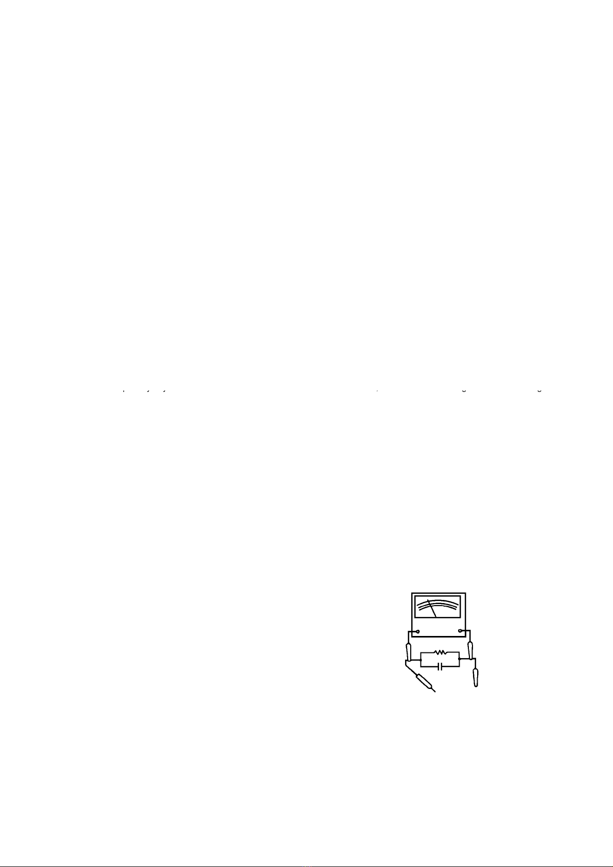
Transformer must be used as a safety precaution and to If a reliable leakage current tester is not available, this
prevent possible damage to transistors. The Isolation alternate method of measurement should be used.
Transformer should be connected between the TV line Using two clip leads, connect a 1500 ohm, 10 watt
cord plug and the AC power outlet. resistor paralleled by a 0.15µF capacitor in series with
a known earth ground, such as a water pipe or conduit
When removing springs or spring mounted parts from the and the metal part to be checked. Use a VTVM or
tuner, tuner cluster or chassis, shatterproof goggles must VOM with 1000 ohms per volt, or higher, sensitivity to
be worn. Keep others without shatterproof goggles away. measure this AC voltage drop across the resistor. Any
reading of 0.35 volt RMS or more is excessive and
indicates a potential shock hazard which must be
corrected before returning the receiver to the owner.
TO EXPOSED
METAL PARTS
TO KNOWN
EARTH GROUND
10µF
TEST PROBE
VT VM
AC SCALE
0.15K OHMS
10W
A1-1
ABOUT LEAD FREE SOLDER (PbF)
Distinction of PbF PCB:
PCBs (manufactured) using lead free solder will have a PbF printing on the PCB.
(Please refer to figures.)
Caution:
• Pb free solder has a higher melting point than standard solder;
Typically the melting point is 86oF~104oF(30oC~40oC) higher.
Please use a soldering iron with temperature control and adjust it to 650oF ± 20oF (350oC ± 10oC).
In case of using high temperature soldering iron, please be careful not to heat too long.
•
Pb free solder will tend to splash when heated too high (about 1100
o
F/ 600
o
C).
•
Pb free solder will tend to splash when heated too high (about 1100
F/ 600
C).
• All products with the printed circuit board with PbF printing must be serviced with lead free solder.
When soldering or unsoldering, completely remove all of the solder from the pins or solder area,
and be sure to heat the soldering points with the lead free solder until it melts sufficiently.
Recommendations
Recommended lead free solder composition is Sn-3.0Ag-0.5Cu.
A1-2
IMPORTANT SERVICE SAFETY INFORMATION
.......................................................................................................
A1-1
ABOUT LEAD FREE SOLDER (PbF)
...........................................................................................................................
A1-2
TABLE OF CONTENTS
..................................................................................................................................................
A2-1
GENERAL SPECIFICATIONS
........................................................................................................................................
A3-1~A3-6
DISASSEMBLY INSTRUCTIONS
1.
REMOVAL OF MECHANICAL PARTS AND P. C. BOARDS........................................................................
B1-1, B1-2
2.
REMOVAL AND INSTALLATION OF FLAT PACKAGE IC............................................................................
B2-1, B2-2
SERVICE MODE LIST
...................................................................................................................................................
C-1
WHEN REPLACING EEPROM (MEMORY) IC
............................................................................................................
C-2
ELECTRICAL ADJUSTMENTS
....................................................................................................................................
D-1~D-6
TROUBLESHOOTING GUIDE
.......................................................................................................................................
E-1~E-3
IC DESCRIPTION
...........................................................................................................................................................
F-1~F-7
SEMICONDUCTOR BASE CONNECTIONS
................................................................................................................
G-1
BLOCK DIAGRAMS
MAIN & FRC.....................................................................................................................................
H-1, H-2
POWER............................................................................................................................................
H-3, H-4
PRINTED CIRCUIT BOARDS
MAIN/LED........................................................................................................................................
I-1, I-2
FRC/OPERATION..............................................................................................................................
I-3, I-4
POWER/REMOCON..........................................................................................................................
I-5~I-8
SCHEMATIC DIAGRAMS
FLASH.............................................................................................................................................
J-1, J-2
DDR2...............................................................................................................................................
J-3, J-4
HDMI................................................................................................................................................
J-5, J-6
LVDS...............................................................................................................................................
J-7, J-8
MICON..............................................................................................................................................
J-9, J-10
SCALER POWER..............................................................................................................................
J-11, J-12
TABLE OF CONTENTS
SCALER POWER..............................................................................................................................
J-11, J-12
TUNER.............................................................................................................................................
J-13, J-14
SCALER VIDEO/AUDIO....................................................................................................................
J-15, J-16
JACK...............................................................................................................................................
J-17, J-18
REGULATOR....................................................................................................................................
J-19, J-20
SOUND............................................................................................................................................
J-21, J-22
SOUND2..........................................................................................................................................
J-23, J-24
JACK2.....................................................................................................................................................................
J-25, J-26
EMI FILTER......................................................................................................................................
J-27, J-28
PFC / SUB_POWER...........................................................................................................................
J-29, J-30
MAIN_POWER..................................................................................................................................
J-31, J-32
LVDS1.............................................................................................................................................
J-33, J-34
DDR................................................................................................................................................
J-35, J-36
FRC.................................................................................................................................................
J-37, J-38
POWER............................................................................................................................................
J-39 J-40
OPERATION ....................................................................................................................................
J-41, J-42
INTERCONNECTION DIAGRAM
...................................................................................................................................
J-43, J-44
WAVEFORMS
................................................................................................................................................................
K-1
MECHANICAL EXPLODED VIEWS
.............................................................................................................................
L-1, L-2
MECHANICAL REPLACEMENT PARTS LIST
............................................................................................................
M1-1
ACCESSORY REPLACEMENT PARTS LIST
.............................................................................................................
M1-1
ELECTRICAL REPLACEMENT PARTS LIST
..............................................................................................................
M2-1~M2-8
A2-1
GENERAL SPECIFICATIONS
G-1 TV LCD LCD Size / Visual Size 42.02 inch / 1,067.3mmV
System LCD Type Color TFT LCD
Number of Pixels 1920(H) x 1080(V)
Double Scan Yes
View Range Left/Right 88/88 degree
Up/Down 88/88 degree
Bright Dot n 0
Zero Bright Dot Ratio --
Color System NTSC
Speaker 2 Speaker
Position Bottom
Size 0.8 x 5.9 inch
Impedance 8 ohm
WOOFER 1 Speaker
Position Back
Size 4.3 x 5.4 inch
Impedance 4 ohm
Sound Output Max 10W + 10W + 15W
10%(Typical) ---
G-2 Tuning Broadcasting System Analog US System M
System Digital ATSC(8VSB)/QAM
Tuner and System 1Tuner
Receive CH Destination US (W/CABLE)
CH Coverage 2~69, 4A, A-5~A-1, A~I, J~W, W+1~W+94
Intermediate
Digital 44.00MHz
Frequency Analog Picture(FP) 45.75MHz
Sound(FS) 41.25MHz
FP-FS 4.50MHz
Preset CH
No
<
=
Preset CH
No
Stereo/Dual TV Sound US-Stereo
Tuner Sound Muting Yes
G-3 Signal Video Signal Input Level 1 V p-p/75 ohm
Output Level --
S/N Ratio (Weighted) --
Horizontal Resolution at DVD Mode --
--
RGB Signal Output Level --
Audio Signal Input Level -8.0dBm/50k ohm
Output Level at DVD --
at TV --
Digital Output Level 0.5 V p-p/75 ohm
S/N Ratio at DVD (Weighted) --
Harmonic Distortion --
Frequency Response : at DVD --
at Video CD --
at SVCD --
at CD --
G-4 Power Power Source AC 120V, 60Hz
DC --
Power Consumption at AC 135W at 120V 60Hz
at DC --
Stand by (at AC) 0.3W at 120V 60Hz
Energy Star Yes
Per Year -- kWh/Year
Protector Power Fuse Yes
Safety Circuit Yes
IC Protector(Micro Fuse) Yes
G-5 Regulation Safety UL(UL60065_7th)/cUL(CSA E60065_03)
Radiation FCC/IC
Laser --
G-6 Temperature Operation
+5
o
C ~ +40
o
C
Storage
-20
o
C ~ +60
o
C
Space Around Unit 10cm (4inch)
G-7 Operating Humidity Less than 80% RH
A3-1
GENERAL SPECIFICATIONS
G-8 Clock and Clock No
Timer Sleep Timer Max Time 120 Min
On Timer Program Yes 1Program
Off Timer Program No
Game Timer No
Timer Back-up (at Power Off Mode) more than -- Min Sec
G-9 Remote Unit RC-SF
Control Glow in Dark Remocon No
Remocon Format JVC
Format JVC
Custom Code 03h
、
0Fh
Power Source Voltage(D.C) 3V
UM size x pcs UM-3 x 2 pcs
Total Keys 31 Keys
Keys Power Yes
1 Yes
2 Yes
3 Yes
4 Yes
5 Yes
6 Yes
7 Yes
8 Yes
9 Yes
0 Yes
- Yes
Recall (Quick View) Yes
Sleep Yes
Muting(Mute)
Yes
Muting(Mute)
Yes
Left Yes
Right Yes
Up Yes
Down Yes
CH+ Yes
CH- Yes
VOL+ Yes
VOL- Yes
CH+ / Up No
CH- / Down No
VOL+ / Right No
VOL- / Left No
Menu Yes
Reset No
Exit Yes
Enter Yes
Input Select Yes
CCD (Closed Caption) Yes
Display Yes
Picture Size Yes
FAV + No
FAV - No
Audio Yes
A3-2
GENERAL SPECIFICATIONS
G-10 Features Auto Shut Off Yes
Auto Search No
Power On Memory Yes
Hotel Mode Yes
Comb Filter Yes
3 -D
Game Position No
Auto Setup Yes
Language No
TV Location Yes
Signal Type Yes
Automatic Search Yes
Picture Setting(TV) Yes
Picture Preference Yes
Brightness , Contrast , Color Yes
Tint Yes
Sharpness Yes
Color Temperature Yes
DNR Yes
Backlight Yes
Picture Setting(PC) Yes
HOR Position , VER Position Yes
Phase, Clock Yes
Red, Green, Blue No
Auto Adjust Yes
Audio MTS Yes
Tone Control (Bass/Treble/Balance) Yes
Stable Sound No
Surround
No
Surround
No
BBE No
SRS WOW (SRS 3D/Focus/Tru Bass) No
HDMI Audio Yes
Speakers(Variable Audio Out) Yes
Tuning CH Program Yes
Air/Cable Yes
ADD/DELETE Yes
Label CH Label Yes
Video Label Yes
Favorite CH No
V-Chip Yes
Type USA Type
RRT Setup Yes
Lock Hotel Lock No
Channel Lock No
Video Lock No
Panel Lock No
Menu Language English
French
DBC (Dynamic Backlight Control) Yes
Dynamic Gamma No
Signal Meter (DTV Signal) Yes
Closed Caption Yes
CC Advanced Yes
V-Chip Clear Yes
Picture Size Yes
HD Zoom Yes
Film Mode Yes
Aspect No
PFC(Power Factor circuit) No
Freeze frame No
PIP/POP No
Direct Input Selection Yes
PC Plug and Play No
Power On/Off Sound No
Power On LED On/Off Yes
Motion 120Hz Yes
A3-3
GENERAL SPECIFICATIONS
Digital Out Dolby Digital Yes
MPEG No
PCM Yes
DTS No
PC Monitor Input Yes
VGA (640x480) Yes (60,72,75Hz)
VGA (720x400) Yes (70Hz)
WVGA (848x480) No
SVGA (800x600) Yes (56,60,72,75Hz)
XGA (1024x768) Yes (60,70,75Hz)
WXGA (1280x768) Yes (60Hz)
WXGA (1280x720) No
WXGA (1360x768) Yes (60Hz)
SXGA (1280x1024) Yes (60Hz)
WXGA+ (1440x900) Yes (60Hz)
FHD (1920x1080) Yes (60Hz)
HDMI Input Yes
VGA (640×480) Yes (60Hz)
720×480i (4:3) Yes (60Hz)
720×480i (16:9) Yes (60Hz)
720×480p (4:3) Yes (60Hz)
720×480p (16:9) Yes (60Hz)
720×576i (4:3) No
720×576i (16:9) No
720×576p (4:3) No
720×576p (16:9) No
1280×720p Yes (60Hz)
1920×1080i Yes (60Hz)
1920×1080p
Yes (60Hz)
1920×1080p
Yes (60Hz)
CEC (ORION Standard) No
Deep Color No
xvYCC No
DVI to HDMI Input VGA (640x480) Yes (60,72,75Hz)
VGA (720x400) Yes (70Hz)
WVGA (848x480) No
SVGA (800x600) Yes (56,60,72,75Hz)
XGA (1024x768) Yes (60,70,75Hz)
WXGA (1280x768) Yes (60Hz)
WXGA (1280x720) Yes (60Hz)
WXGA (1360x768) Yes (60Hz)
SXGA (1280x1024) Yes (60Hz)
WXGA+ (1440x900) Yes (60Hz)
FHD (1920x1080) Yes (60Hz)
Component Input Yes
720×480i (4:3) Yes (60Hz)
720×480i (16:9) Yes (60Hz)
720×480p (4:3) Yes (60Hz)
720×480p (16:9) Yes (60Hz)
720×576i (4:3) No
720×576i (16:9) No
720×576p (4:3) No
720×576p (16:9) No
1280×720p Yes (60Hz)
1920×1080i Yes (60Hz)
1920×1080p No
Wall Mount Size W x H(mm) Yes (200 x 200)
Screw Size M6 x 10
Stand Tilt No
Swievel Yes
A3-4
GENERAL SPECIFICATIONS
G-11 Accessories Owner's Manual Language English / French
w/Guarantee Card Yes
Remote Control Unit Yes
Rod Antenna No
Poles --
Terminal --
Loop Antenna No
Terminal --
U/V Mixer No
DC Car Cord (Center+) No
Guarantee Card No
Warning Sheet No
Circuit Diagram No
Antenna Change Plug No
Service Facility List No
Important Safeguard No
Dew/AHC Caution Sheet No
Quick Set-up Sheet No
Battery Yes
UM size x pcs UM-3 x 2 pcs
OEM Brand No
AC Adapter No
AC Cord (for AC Adapter) No
AC Cord No
Cable Tie No
AV Cord (2Pin-1Pin) No
Registration Card (NDL Card) No
300 to 75ohm Antenna Adapter No
Sheet Information (FCC)
No
Sheet Information (FCC)
No
Sheet Information (DTV) No
Sheet Information (CEA) No
Sheet Information (Return) No
Sheet Information (Picture Quality) No
Sheet Information (Sheet Set Up) No
Sheet Information (HDMI) No
Cleaning Cloth No
Stand Screw Yes (4pcs)
Stand Yes
G-12 Interface Switch Front Power Yes
Channel Up/Menu Up Yes
Channel Down/Menu Down Yes
Volume Up/Menu > Yes
Volume Down/Menu < Yes
Menu Yes
Play No
Eject No
Skip+, Search+ No
Skip-, Search- No
Still/Pause No
Stop No
Main Power SW No
Input Select/Enter Yes
Rear Main Power SW No
Indicator Power/Stand-By Yes (Blue / Red)
Power Wake Up No
On Timer No
Terminals Side Video Input 1 RCA x 1
Audio Input 1 RCA x 2(L/MONO, R)
S - Input 1 No
HDMI Input 1 Yes
Analog Audio PC Audio Input Alternative
Other Terminal No
AC Inlet No
USB (Software Update) Yes
USB (JPEG/MP3/Software Update) No
A3-5
GENERAL SPECIFICATIONS
Terminals Rear Video Input 2 RCA x 1
Audio Input 2 RCA x 2(L/MONO, R)
S - Input 2 No
Video Input 3 No
Audio Input 3 No
S - Input 3 No
Video Output No
Audio Output RCA x 2 (Variable) (L, R)
Component Input 1 RCA x 3
Analog Audio Video Input 2 Audio Input Alternative
Component Input 2 No
Analog Audio No
HDMI Input 2 Yes
Analog Audio No
HDMI Input 3 Yes
Analog Audio No
Digital Audio Output Coaxial
VHF/UHF Antenna Input F Type
Other Terminal No
AC Inlet No
PC Monitor Input Yes
Analog Audio Mini Pin Jack( 3.5), STEREO
Sub Woofer Out Yes
DC Jack (Center +) No
G-13 Set Size Approx. W x D x H (mm) 1013.0 x 255.0 x 679.5
w/o Handle, Stand Approx. W x D x H (mm) 1013.0 x 29.8 x 629.0
G-14 Weight Net (Approx.) 15.8kg (34.8 lbs)
Net w/o Handle, Stand (Approx.) 12.8kg (28.2 lbs)
Gross (Approx.)
20.8kg
(45.9 lbs)
Gross (Approx.)
20.8kg
(45.9 lbs)
Gross w/Master Carton (Approx.) --- kg ( --- lbs)
G-15 Carton Master Carton No
Content --- Sets
Material --- / ---
Dimensions W x D x H(mm) ---
Description of Origin ---
Gift Box Material Double/White
W/Color Photo Label Yes
W/Handle No
Dimensions W x D x H(mm) 1148 x 791 x 181
Description of Origin Yes
Drop Test 1 Corner / 3 Edges / 6 Surfaces
Height (cm) 46
Container Stuffing (40' container) 387 Sets/40' container
w/Pallet No
w/Wrapping No
G-16 Material Cabinet Front PC+ABS 94V0 NON-HALOGEN
Rear PS 94V0 NON-DECABROM
Stand GLASS
Jack Panel --
PCB Non-Halogen Demand No
Eyelet Demand Yes
G-17 Environment Environmental standard requirement Green procurement of JVC
Pb-free Phase3(Phase3A)
Measures for Whisker Yes
A3-6
1. REMOVAL OF MECHANICAL PARTS 1-3: BACK CABI ASS'Y (Refer to Fig. 1-3)
AND P.C. BOARDS
1. Remove the 18 screws (1)
2. Remove the 4 screws (2)
CAUTION 3. To detach the Back cabi Ass'y as below lelf side, perfrom
Be careful not to remove the LVDS cable forcibly, because these steps as arrow (A) -> (B) -> (C)-> (D).
the LVDS cable may be damaged.
1-1: STAND ASS'Y (Refer to Fig. 1-1)
1. Remove the 4 screws (1).
2. Remove the Stand Ass'y in the direction of arrow.
DISASSEMBLY INSTRUCTIONS
(1) (1)
Stand Ass'y
(1)
(1)
(1)
(B)
(2)
(1)
(1)
(C)
(1) (1)
(1)
(1)
(1)
(1) (1)
(1)
(1)
(1)
(1)
(1)
(1)
(1)
(1)
(2)
(2)
(2)
(B) (A)
(D)
Back Cabi Ass'y
Front Cabi Ass'y
B1-1
1-2: COVER CONNECTOR/COVER AC (Refer to Fig. 1-2)
1. Remove the Cover Connector in the direction of arrow (A)
2. Remove the screws (1).
3. Remove the Cover Ac in the direction of arrow (B)
4. Disconnect the following connector: (CP6502)
Fig. 1-1
Fig. 1-2
(1)
(A)
(B)
Cover AC Cover Connector
Fig. 1-3
B1-1
1-4: MAIN PCB/FRC PCB (Refer to Fig. 1-4) 1-6: REMOCON PCB/LED PCB/OPERATION PCB
(Refer to Fig. 1-6)
1. Disconnect the following connectors: (CP301, CP302,
CP2808, CP2804, CP6403, CP2201 and CP7601). 1. Remove the screw (1)
2. Remove the 6 screws (1). 2. Remove the Remocon PCB in the direction of arrow (A).
3. Remove the Main PCB in the direction of arrow (A) 3. Remove the Operation PCB in the direction of arrow (B).
4. Disconnect the following connectors:
(CP2301 and CP2302).
5. Remove the 4 screws (2).
6. Remove the FRC PCB in the direction of arrow (B)
7. Remove the FRC PCB in the direction of arrow (B)
Disconnect the following connectors: (CD7601).
8. Remove the FRC PCB in the direction of arrow (B)
Unlock the 2 screws (2)
9. Remove the FRC PCB in the direction of arrow (B)
Remove the LED PCB in the direction of arrow (C).
DISASSEMBLY INSTRUCTIONS
(2)
(1)
(1)
(1)
FRC PCB
Main PCB
(1) (1) (1)
(2)
(2)
(2)
(A)
(B)
LED PCB
(C)
Fig. 1-6
(A)
(1)
(B)
Operation
Remocon PCB
B1-2
1-5: MAIN PCB (Refer to Fig. 1-5)
1. Disconnect the following connectors: (CP6401).
2. Remove the 10 screws (1)
3. Remove the Power PCB in the direction of arrow.
Fig. 1-4
(1)
(1)
(1) (1)
(1)
(1)
(1)
(1) (1)
(1) Power PCB
Fig. 1-5
B1-2
2. REMOVAL AND INSTALLATION OF
3. When IC starts moving back and forth easily after
FLAT PACKAGE IC
desoldering completely, pickup the corner of the IC using
tweezers and remove the IC by moving with the IC
REMOVAL desoldering machine. (Refer to Fig. 2-3.)
1.
Put Masking Tape (cotton tape) around the Flat Package
NOTE
IC to protect other parts from any damage.
(Refer to Fig. 2-1.) Some ICs on the PCB are affixed with glue, so be
careful not to break or damage the foil of each IC
NOTE leads or solder lands under the IC when removing it.
Masking is carried out on all the parts located within
10 mm distance from IC leads.
DISASSEMBLY INSTRUCTIONS
Fig. 2
-
1
Masking Tape
(Cotton Tape) IC
Blower type IC
desoldering machine
Tweezers
B2-1
2. Heat the IC leads using a blower type IC desoldering
machine. (Refer to Fig. 2-2.)
NOTE
Do not rotate or move the IC back and forth , until IC 4. Peel off the Masking Tape.
can move back and forth easily after desoldering the
leads completely. 5. Absorb the solder left on the pattern using the Braided
Shield Wire. (Refer to Fig. 2-4.)
NOTE
Do not move the Braided Shield Wire in the vertical
direction towards the IC pattern.
Fig. 2
-
1
Fig. 2-2
Fig. 2-3
Fig. 2-4
Blower type IC
desoldering machine
IC
IC
IC pattern
Braided Shield Wire
Soldering Iron
B2-1
INSTALLATION 4. When bridge-soldering between terminals and/or the
soldering amount are not enough, resolder using a
1. Take care of the polarity of new IC and then install the Thintip Soldering Iron. (Refer to Fig. 2-8.)
new IC fitting on the printed circuit pattern. Then solder
each lead on the diagonal positions of IC temporarily.
(Refer to Fig. 2-5.)
5. Finally, confirm the soldering status on four sides of the
IC using a magnifying glass.
Confirm that no abnormality is found on the soldering
position and installation position of the parts around the
IC. If some abnormality is found, correct by resoldering.
NOTE
2. Supply the solder from the upper position of IC leads When the IC leads are bent during soldering and/or
sliding to the lower position of the IC leads. repairing, do not repair the bending of leads. If the
(Refer to Fig. 2-6.) bending of leads are repaired, the pattern may be
damaged. So, always be sure to replace the IC in this
DISASSEMBLY INSTRUCTIONS
Fig. 2-5
Fig. 2-8
IC
Thin-tip Soldering Iron
Soldering Iron
Solder temporarily Solder temporarily
B2-2
damaged. So, always be sure to replace the IC in this
case.
3. Absorb the solder left on the lead using the Braided
Shield Wire. (Refer to Fig. 2-7.)
NOTE
Do not absorb the solder to excess.
Fig. 2-6
Fig. 2-7
IC
Soldering Iron
Supply soldering
from upper position
to lower position
Solder
Soldering Iron
IC
Braided Shield Wire
B2-2
This unit is provided with the following SERVICE MODES so you can repair, examine and adjust easily.
To enter to the SERVICE MODE function, press and hold both buttons simultaneously on the main unit and on the remote
control for more than a the standard time in the appropriate condition. (See below chart.)
VOL. DOWN
(Minimum)
Initialization of factory TV data.
POWER ON
1
2 sec.
NOTE:
If you set factory initialization, the memories are reset such
as the channel setting, and the POWER ON total hours.
VOL. DOWN
Can be checked of the INITIAL DATA of MEMORY IC.
(Minimum)
Refer to the "WHEN REPLACING EEPROM (MEMORY) IC".
Check of the SUM DATA, POWER ON total hours and MICON
POWER ON
8
2 sec.
VERSION on the screen.
Refer to the "WHEN REPLACING EEPROM (MEMORY) IC".
Display of the Adjustment MENU on the screen.
POWER ON
9
2 sec.
Refer to the "ELECTRICAL ADJUSTMENT" (On-Screen Display
Adjustment).
VOL. DOWN
Releasing of HOTEL MODE FUNCTION
(Minimum)
Refer to the "HOTEL MODE FUNCTION".
VOL. DOWN
(Minimum)
POWER ON
MENU
2 sec.
VOL. DOWN
(Minimum)
POWER ON 0 2 sec.
POWER ON 6 2 sec.
Releasing of V-CHIP PASSWORD.
VOL. DOWN
(Minimum)
SERVICE MODE LIST
Set
Condition Set Key Remocon
Key
Standard
Time Operations
C-1
(Minimum)
Refer to the "HOTEL MODE FUNCTION".
POWER ON
MENU
2 sec.
C-1
WHEN REPLACING EEPROM (MEMORY) IC
C-2
CONFIRMATION OF CHECK SUM, POWER ON TOTAL HOURS AND MICON VERSION
Initial total of MEMORY IC, POWER ON total hours and MICON VERSIONcan be checked on the screen. Total hours are
displayed in 16 system of notation.
NOTE:
If you set a factory initialization, the total hours is reset to "0".
Please refer to "CONFIRMATION OF INITIAL DATA" when SUM DATA is not corresponding.
1. Turn on the POWER, and set to the ALL mode.
2. Set the VOLUME to minimum.
3. Press both VOL. DOWN button on the set and Channel button
(8)
on the remote control for more than 2 seconds.
4. After the confirmation of each check sum, turn off the power.
NOTE:
The each item value might be different according to each set.
CHECK SUM : 68D3 Initial setting data check sum.
LCD PWR ON : 0000 POWER ON total hours.
HDMI data check sum.
HDMI SUM : AE00
= (16 x 16 x 16 x thousands digit value)
HDMI data check sum.
HDMI SUM : AE00
= (16 x 16 x 16 x thousands digit value)
Main Micon check Version. DTV : CA58I09101 + (16 x 16 x hundreds digit value)
EEPROM check Version. EEPROM : J3CQ02AM00 + (16 x tens digit value)
Parameter check Picture Quality. QUALITY : @@@@.@@ (@@@@@@ @@:@@:@@) + (ones digit value)
Parameter check Picture Size. SCALING : @@@@.@@ (@@@@@@ @@:@@:@@)
FRC check version. FRC : 010F
FIG. 1
CONFIRMATION OF INITIAL DATA
If a service repair is undertaken where it has been required to change the MEMORY IC, the following steps should be taken
to ensure correct data settings while making reference to INITIAL SETTING TABLE (Attached "INITIAL DATA").
1. Turn on the POWER, and set to the ALL mode.
2. Set the VOLUME to minimum.
3. Press both VOL. DOWN button on the set and Channel button
(6)
on the remote control for more than 2 seconds.
ADDRESS and DATA should appear as FIG 2.
NOTE: No need to set data other position than 0200~03FF.
ADDRESS DATA
INIT :
0001 0087
DTV : CA58I09101
EEPROM : J3CQ02AM00
EEPROM : J3CQ02AM00
4. ADDRESS is now selected and should "blink". Using the UP/DOWN buton on the remote, step through the ADDRESS
until required ADDRESS to be changed is reached.
5. Press LEFT/RIGHT button to select DATA. When DATA is selected, it will "blink".
6. Again, step through the DATA using UP/DOWN button until required DATA value has been selected.
7. Pressing LEFT/RIGHT button will take you back to ADDRESS for further selection if necessary.
FIG. 2
7. Pressing LEFT/RIGHT button will take you back to ADDRESS for further selection if necessary.
8. Repeat steps 4 to 6 until all data has been checked.
9. When satisfied correct DATA has been entered, turn POWER off (return to STANDBY MODE) to finish DATA input.
After the data input, set to the initializing of shipping.
10.
Turn on the Power.
11.
Set the VOLUME to minimum.
12.
Press both VOL. DOWN button on the set and Channel button
(1)
on the remote control for more than 2 seconds.
13.
After the finishing of the initializing of shipping, the unit will turn off automatically.
The unit will now have the correct DATA for the new MEMORY IC.
C-2
NO. FUNCTION NO. FUNCTION
Read and perform these adjustments when repairing the 03 R DRIVE(N) 35 TINT
circuits or replacing electrical parts or PCB assemblies. 04 R CUTOFF(N) 36 SHARP H1 MAX
05 G DRIVE(N) 37 SHARP H1 MIN
CAUTION 06 G CUTOFF(N) 38 SHARP H2 MAX
07 B DRIVE(N) 39 SHARP H2 MIN
• Use an isolation transformer when performing any 08 B CUTOFF(N) 40 SHARP H3 MAX
service on this chassis. 09 R DRIVE(C) 41 SHARP H3 MIN
• When removing a PCB or related component, after 10 R CUTOFF(C) 42 SHARP H4 MAX
unfastening or changing a wire, be sure to put the wire 11 G DRIVE(C) 43 SHARP H4 MIN
back in its original position. 12 G CUTOFF(C) 44 SHARP H5 MAX
• When you exchange IC and Transistor with a heat sink, 13 B DRIVE(C) 45 SHARP H5 MIN
apply silicon grease (YG6260M) on the contact section 14 B CUTOFF(C) 46 SHARP V1 MAX
of the heat sink. Before applying new silicon grease, 15 R DRIVE(W) 47 SHARP V1 MIN
remove all the old silicon grease. (Old grease may 16 R CUTOFF(W) 48 SHARP V2 MAX
cause damages to the IC and Transistor). 17 G DRIVE(W) 49 SHARP V2 MIN
18 G CUTOFF(W) 50 CONTRAST CENTER
Prepare the following measurement tools for electrical 19 B DRIVE(W) 51 CONTRAST MAX
adjustments. 20 B CUTOFF(W) 52 CONTRAST MIN
29 BAK LIGHT CENT 53 COLOR CENTER
1. Pattern Generator 30 BAK LIGHT MAX 54 COLOR MAX
31 BAK LIGHT MIN 55 COLOR MIN
On-Screen Display Adjustment 32 BRIGHTNESS CENT 58 CONTRAST 40
33 BRIGHTNESS MAX
1.
Set the VOLUME to minimum.
34
BRIGHTNESS MIN
ELECTRICAL ADJUSTMENTS
1. ADJUSTMENT PROCEDURE
Fig. 1
-
2
D-1
1.
Set the VOLUME to minimum.
34
BRIGHTNESS MIN
2. Press the VOL. DOWN button on the set and the
channel button (9) on the remote control for more than
2 seconds to display adjustment mode on the screen as
2. BASIC ADJUSTMENTS
shown in Fig. 1-1.
2-1: WHITE BALANCE
1. Place the set in Aging Test for more than 15 minutes.
TV 2. Receive the gray scale pattern from the Pattern
Full Generator.
3. Press the INPUT SELECT button on the remote control
to set to the AV mode.
4. Using the remote control, set the brightness and
contrast to normal position.
03 R DRIVE(N) 7 5. Activate the adjustment mode display of Fig. 1-1 and
press the channel button (03) on the remote control to
select "R DRIVE(N)".
Function 6. Press the UP/DOWN button on the remote control
to select the "R CUTOFF(N)", "B DRIVE(N)",
"B CUTOFF(N)", "R DRIVE(C)", "R CUTOFF(C)",
"B DRIVE(C)", "B CUTOFF(C)", "R DRIVE(W)",
3. Use the UP/DOWN button or Channel button (0-9) "R CUTOFF(W), "B DRIVE(W)" or "B CUTOFF(W)".
on the remote control to select the options shown in 7. Adjust the LEFT/RIGHT button on the remote control
Fig. 1-2.to whiten the R DRIVE(N), R CUTOFF(N),
4. Press the MENU button on the remote control to end B DRIVE(N), B CUTOFF(N), R DRIVE(C),
the adjustments. R CUTOFF(C), B DRIVE(C), B CUTOFF(C),
5. To display the adjustment screen for TV, AV, R DRIVE(W), R CUTOFF(W), B DRIVE(W) and
COMPONENT, HDMI and PC mode, press the B CUTOFF(W) at each step tone sections equally.
INPUT SELECT button on the remote control. 8. Perform the above adjustments 6 and 7 until the white
6. Receive the DIGITAL broadcasting. color is achieved.
7. To display the adjustment screen for DTV mode, select
the digital channel.
8. Press the VOL.DOWN button on the set and the channel
(9) on the remote control for more than 2 seconds.
Step No.
Fig. 1-1
Fig. 1
-
2
D-1
2-2: BRIGHTNESS CENT 2-3: CONTRAST MAX
1. Place the set in Aging Test for more than 15 minutes. 1. Place the set in Aging Test for more than 15 minutes.
2. Receive the color bar pattern. (RF Input) 2. Receive the color bar pattern. (RF Input)
3. Using the remote control, set the brightness and 3. Using the remote control, set the brightness and
contrast to normal position. contrast to normal position.
4. Activate the adjustment mode display of Fig. 1-1 and 4. Activate the adjustment mode display of Fig. 1-1 and
press the channel button (32) on the remote control to press the channel button (51) on the remote control to
select "BRIGHTNESS CENT". select "CONTRAST MAX".
5. Press the LEFT/RIGHT button on the remote control 5. Press the LEFT/RIGHT button on the remote control
until the contrast step No. becomes "115". until the contrast step No. becomes "153".
6. Check if the picture is normal. 6. Check if the picture is normal.
7. Receive the color bar pattern. (VIDEO Input) 7. Receive the color bar pattern. (VIDEO Input)
8. Using the remote control, set the brightness and 8. Using the remote control, set the brightness and
contrast to normal position. contrast to normal position.
9. Press the INPUT SELECT button on the remote 9. Press the INPUT SELECT button on the remote
control to set to the AV mode. control to set to the AV mode.
Activate the adjustment mode display of Fig. 1-1 and 10. Activate the adjustment mode display of Fig. 1-1 and
press the channel button (32) on the remote control to press the channel button (51) on the remote control to
select "BRIGHTNESS CENT". select "CONTRAST MAX".
Press the LEFT/RIGHT button on the remote control 11. Press the LEFT/RIGHT button on the remote control
until the contrast step No. becomes "117". until the contrast step No. becomes "137".
Check if the picture is normal. 12. Check if the picture is normal.
Receive the color bar pattern. (COMPONENT Input) 13. Receive the color bar pattern. (COMPONENT Input)
Using the remote control, set the brightness and 14. Using the remote control, set the brightness and
contrast to normal position.
ELECTRICAL ADJUSTMENTS
12.
13.
14.
11.
10.
D-2
contrast to normal position.
Press the INPUT SELECT button on the remote 15. Press the INPUT SELECT button on the remote
control to set to the COMPONENT mode. control to set to the COMPONENT mode.
Activate the adjustment mode display of Fig. 1-1 and 16. Activate the adjustment mode display of Fig. 1-1 and
press the channel button (32) on the remote control to press the channel button (51) on the remote control to
select "BRIGHTNESS CENT". select "CONTRAST MAX".
Press the LEFT/RIGHT button on the remote control 17. Press the LEFT/RIGHT button on the remote control
until the contrast step No. becomes "117". until the contrast step No. becomes "132".
Check if the picture is normal. 18. Check if the picture is normal.
Receive the color bar pattern. (HDMI Input) 19. Receive the color bar pattern. (HDMI Input)
Using the remote control, set the brightness and 20. Using the remote control, set the brightness and
contrast to normal position. contrast to normal position.
Press the INPUT SELECT button on the remote 21. Press the INPUT SELECT button on the remote
control to set to the HDMI mode. control to set to the HDMI mode.
Activate the adjustment mode display of Fig. 1-1 and 22. Activate the adjustment mode display of Fig. 1-1 and
press the channel button (32) on the remote control to press the channel button (51) on the remote control to
select "BRIGHTNESS CENT". select "CONTRAST MAX".
Press the LEFT/RIGHT button on the remote control 23. Press the LEFT/RIGHT button on the remote control
until the contrast step No. becomes "116". until the contrast step No. becomes "133".
Check if the picture is normal. 24. Check if the picture is normal.
21.
22.
16.
17.
18.
20.
15.
19.
23.
24.
D-2
2-4: CONTRAST CENTER 2-5: CONTRAST 40
1. Place the set in Aging Test for more than 15 minutes. 1. Place the set in Aging Test for more than 15 minutes.
2. Receive the color bar pattern. (RF Input) 2. Receive the color bar pattern. (RF Input)
3. Using the remote control, set the brightness and 3. Using the remote control, set the brightness and
contrast to normal position. contrast to normal position.
4. Activate the adjustment mode display of Fig. 1-1 and 4. Activate the adjustment mode display of Fig. 1-1 and
press the channel button (50) on the remote control to press the channel button (58) on the remote control to
select "CONTRAST CENTER". select "CONTRAST 40".
5. Press the LEFT/RIGHT button on the remote control 5. Press the LEFT/RIGHT button on the remote control
until the contrast step No. becomes "106". until the contrast step No. becomes "144".
6. Check if the picture is normal. 6. Check if the picture is normal.
7. Receive the color bar pattern. (VIDEO Input) 7. Receive the color bar pattern. (VIDEO Input)
8. Using the remote control, set the brightness and 8. Using the remote control, set the brightness and
contrast to normal position. contrast to normal position.
9. Press the INPUT SELECT button on the remote control 9. Press the INPUT SELECT button on the remote control
to set to the AV mode. to set to the AV mode.
Activate the adjustment mode display of Fig. 1-1 and 10. Activate the adjustment mode display of Fig. 1-1 and
press the channel button (50) on the remote control to press the channel button (58) on the remote control to
select "CONTRAST CENTER". select "CONTRAST 40".
Press the LEFT/RIGHT button on the remote control 11. Press the LEFT/RIGHT button on the remote control
until the contrast step No. becomes "97". until the contrast step No. becomes "129".
Check if the picture is normal. 12. Check if the picture is normal.
Receive the color bar pattern. (COMPONENT Input) 13. Receive the color bar pattern. (COMPONENT Input)
Using the remote control, set the brightness and 14. Using the remote control, set the brightness and
contrast to normal position.
ELECTRICAL ADJUSTMENTS
10.
11.
12.
13.
14.
D-3
contrast to normal position.
Press the INPUT SELECT button on the remote control 15. Press the INPUT SELECT button on the remote control
to set to the COMPONENT mode. to set to the COMPONENT mode.
Activate the adjustment mode display of Fig. 1-1 and 16. Activate the adjustment mode display of Fig. 1-1 and
press the channel button (50) on the remote control to press the channel button (58) on the remote control to
select "CONTRAST CENTER". select "CONTRAST 40".
Press the LEFT/RIGHT button on the remote control 17. Press the LEFT/RIGHT button on the remote control
until the contrast step No. becomes "94". until the contrast step No. becomes "124".
Check if the picture is normal. 18. Check if the picture is normal.
Receive the color bar pattern. (HDMI Input) 19. Receive the color bar pattern. (HDMI Input)
Using the remote control, set the brightness and 20. Using the remote control, set the brightness and
contrast to normal position. contrast to normal position.
Press the INPUT SELECT button on the remote control 21. Press the INPUT SELECT button on the remote control
to set to the HDMI mode. to set to the HDMI mode.
Activate the adjustment mode display of Fig. 1-1 and 22. Activate the adjustment mode display of Fig. 1-1 and
press the channel button (50) on the remote control to press the channel button (58) on the remote control to
select "CONTRAST CENTER". select "CONTRAST 40".
Press the LEFT/RIGHT button on the remote control 23. Press the LEFT/RIGHT button on the remote control
until the contrast step No. becomes "94". until the contrast step No. becomes "125".
Check if the picture is normal. 24. Check if the picture is normal.
15.
16.
17.
18.
19.
20.
21.
22.
23.
24.
D-3
2-6: Confirmation of Fixed Value (Step No.)
Please check if the fixed values of each of the adjustment item is set correctly referring below. (TV/AV/COMPONENT/HDMI/PC/DTV)
AV PC
CVBS 480i 480p 720p 1080i 480i 480p 720p 1080i 1080p VGA VGA XGA ALL FORMAT 480i 480p 720p 1080i 1080p
Step No. Step No. Step No.
03 R.DRIVE(N) * * * * * * * * * * * * * * * * * * * *
04 R CUTOFF(N) * * * * * * * * * * * * * * * * * * * *
05 G DRIVE(N) 0 0 0 0 0 0 0 0 0 0 0 0 0 0 0 0 0 0 0 0
06 G CUTOFF(N) 0 0 0 0 0 0 0 0 0 0 0 0 0 0 0 0 0 0 0 0
07 B DRIVE(N) * * * * * * * * * * * * * * * * * * * *
08 B CUTOFF(N) * * * * * * * * * * * * * * * * * * * *
09 R.DRIVE(C) * * * * * * * * * * * * * * * * * * * *
10 R CUTOFF(C) * * * * * * * * * * * * * * * * * * * *
11 G DRIVE(C) 0 0 0 0 0 0 0 0 0 0 0 0 0 0 0 0 0 0 0 0
12 G CUTOFF(C) 0 0 0 0 0 0 0 0 0 0 0 0 0 0 0 0 0 0 0 0
13 B DRIVE(C) * * * * * * * * * * * * * * * * * * * *
14 B CUTOFF(C) * * * * * * * * * * * * * * * * * * * *
15 R.DRIVE(W) * * * * * * * * * * * * * * * * * * * *
16 R CUTOFF(W) * * * * * * * * * * * * * * * * * * * *
17 G DRIVE(W) 0 0 0 0 0 0 0 0 0 0 0 0 0 0 0 0 0 0 0 0
18 G CUTOFF(W) 0 0 0 0 0 0 0 0 0 0 0 0 0 0 0 0 0 0 0 0
19 B DRIVE(W) * * * * * * * * * * * * * * * * * * * *
20 B CUTOFF(W) * * * * * * * * * * * * * * * * * * * *
29 BAK LIGHT CENT 52 52 52 52 52 52 52 52 52 52 52 52 52 52 52 52 52 52 52 52
30 BAK LIGHT MAX 100 100 100 100 100 100 100 100 100 100 100 100 100 100 100 100 100 100 100 100
31 BAK LIGHT MIN 8 8 8 8 8 8 8 8 8 8 8 8 8 8 8 8 8 8 8 8
32 BRIGHTNESS CENT 115 117 117 116 116 116 116 116 116 116 116 116 116 116 116 122 122 122 122 122
33 BRIGHTNESS MAX 200 200 200 200 200 200 200 200 200 200 200 200 200 200 200 200 200 200 200 200
34 BRIGHTNESS MIN 30 30 30 30 30 30 30 30 30 30 30 30 30 30 30 30 30 30 30 30
35 TINT 47 46 53 53 53 53 49 49 49 49 49 35 44 44 44 56 56 56 56 56
36 SHARP H1 MAX 255 255 255 255 255 255 255 255 255 255 255 255 255 255 255 255 255 255 255 255
37 SHARP H1 MIN 0 0 0 0 0 0 0 0 0 0 0 0 0 0 0 0 0 0 0 0
38 SHARP H2 MAX 255 255 255 255 255 255 255 255 255 255 255 255 255 255 255 255 255 255 255 255
39 SHARP H2 MIN 0 0 0 0 0 0 0 0 0 0 0 0 0 0 0 0 0 0 0 0
40 SHARP H3 MAX 255 255 255 255 255 255 255 255 255 255 255 255 255 255 255 255 255 255 255 255
41 SHARP H3 MIN 0 0 0 0 0 0 0 0 0 0 0 0 0 0 0 0 0 0 0 0
42 SHARP H4 MAX 255 255 255 255 255 255 255 255 255 255 255 255 255 255 255 255 255 255 255 255
43 SHARP H4 MIN 0 0 0 0 0 0 0 0 0 0 0 0 0 0 0 0 0 0 0 0
44 SHARP H5 MAX 255 255 255 255 255 255 255 255 255 255 255 255 255 255 255 255 255 255 255 255
45 SHARP H5 MIN 0 0 0 0 0 0 0 0 0 0 0 0 0 0 0 0 0 0 0 0
46 SHARP V1 MAX 255 255 255 255 255 255 255 255 255 255 255 255 255 255 255 255 255 255 255 255
47 SHARP V1 MIN 0 0 0 0 0 0 0 0 0 0 0 0 0 0 0 0 0 0 0 0
48 SHARP V2 MAX 255 255 255 255 255 255 255 255 255 255 255 255 255 255 255 255 255 255 255 255
49 SHARP V2 MIN 0 0 0 0 0 0 0 0 0 0 0 0 0 0 0 0 0 0 0 0
50 CONTRAST CENTER * * * * * * * * * * * * * * * * * * * *
51 CONTRAST MAX * * * * * * * * * * * * * * * * * * * *
52 CONTRAST MIN 60 60 60 60 60 60 60 60 60 60 60 60 60 60 60 60 60 60 60 60
53 COLOR CENTER 227 218 223 223 223 223 227 227 227 227 227 227 210 210 210 217 217 217 217 217
54 COLOR MAX 255 255 255 255 255 255 255 255 255 255 255 255 255 255 255 255 255 255 255 255
55 COLOR MIN 0 0 0 0 0 0 0 0 0 0 0 0 0 0 0 0 0 0 0 0
58 CONTRAST 40 * * * * * * * * * * * * * * * * * * * *
NOTE: For the step no. with * mark, please adjust it according to the situation of the set.
Step No.
ELECTRICAL ADJUSTMENTS
COMPONENT
NO. FUNCTION TV HDMI
Step No.
DVI ---> HDMI
Step No.
DTV
Step No.
D-4 D-5

Other manuals for LT-42EM91

1

Other JVC LED TV manuals

JVC LT-43EC3508 User manual

JVC

JVC LT-43EC3508 User manual

JVC LT-32C340 User manual

JVC

JVC LT-32C340 User manual

JVC LT-24HA48E User manual

JVC

JVC LT-24HA48E User manual

JVC LT-40C550 User manual

JVC

JVC LT-40C550 User manual

JVC BlackCrystal JLE47BC3500 User manual

JVC

JVC BlackCrystal JLE47BC3500 User manual

JVC LT-32EU80U User manual

JVC

JVC LT-32EU80U User manual

JVC LT-65C898 User manual

JVC

JVC LT-65C898 User manual

JVC LT-24C490 User manual

JVC

JVC LT-24C490 User manual

JVC LT-43C890 User manual

JVC

JVC LT-43C890 User manual

JVC LT-55K890 User manual

JVC

JVC LT-55K890 User manual

JVC LT-32C672(B) User manual

JVC

JVC LT-32C672(B) User manual

JVC LT-40E71 User manual

JVC

JVC LT-40E71 User manual

JVC LT-32C695C User manual

JVC

JVC LT-32C695C User manual

JVC LT-32C696 User manual

JVC

JVC LT-32C696 User manual

JVC LT-43C795 User manual

JVC

JVC LT-43C795 User manual

JVC LT-32C670 User manual

JVC

JVC LT-32C670 User manual

JVC LT-32C600 User manual

JVC

JVC LT-32C600 User manual

JVC LT-50VU3005 User manual

JVC

JVC LT-50VU3005 User manual

JVC LT-65N785AN User manual

JVC

JVC LT-65N785AN User manual

JVC LT-43FV130 User manual

JVC

JVC LT-43FV130 User manual

JVC LT-32C795A User manual

JVC

JVC LT-32C795A User manual

JVC LT-43C790 User manual

JVC

JVC LT-43C790 User manual

JVC LT-49C790 User manual

JVC

JVC LT-49C790 User manual

JVC LT-50C550 User manual

JVC

JVC LT-50C550 User manual

Popular LED TV manuals by other brands

Bush DLED55UHDSFIRE instruction manual

Bush

Bush DLED55UHDSFIRE instruction manual

AEG CTV 1902 LED/DVB-T instruction manual

AEG

AEG CTV 1902 LED/DVB-T instruction manual

Philips OLED865 Series quick start guide

Philips

Philips OLED865 Series quick start guide

Samsung QN85B user manual

Samsung

Samsung QN85B user manual

Toshiba 32LF221U19 Quick setup guide

Toshiba

Toshiba 32LF221U19 Quick setup guide

LG LU34 Series quick start guide

LG

LG LU34 Series quick start guide

Insignia NS-39E340A13 Specifications

Insignia

Insignia NS-39E340A13 Specifications

Panasonic TC-55GX800C owner's manual

Panasonic

Panasonic TC-55GX800C owner's manual

Samsung UN65KU7500 E-manual

Samsung

Samsung UN65KU7500 E-manual

Gogen TVH32P320T manual

Gogen

Gogen TVH32P320T manual

LG 32LB550D owner's manual

LG

LG 32LB550D owner's manual

LG 60UN71 Series owner's manual

LG

LG 60UN71 Series owner's manual

Nikkei NF3235ANDROID operating instructions

Nikkei

Nikkei NF3235ANDROID operating instructions

SoundMax SM-LED22M06 instruction manual

SoundMax

SoundMax SM-LED22M06 instruction manual

LG 75NANO75VPA.AFFE owner's manual

LG

LG 75NANO75VPA.AFFE owner's manual

ETERNITY 215/207O-GB-3B-FEGDU user guide

ETERNITY

ETERNITY 215/207O-GB-3B-FEGDU user guide

Avtex L320TRS-v2 user guide

Avtex

Avtex L320TRS-v2 user guide

Sunstech TLEI19HD instruction manual

Sunstech

Sunstech TLEI19HD instruction manual

manuals.online logo
manuals.online logoBrands
  • About & Mission
  • Contact us
  • Privacy Policy
  • Terms and Conditions

Copyright 2025 Manuals.Online. All Rights Reserved.