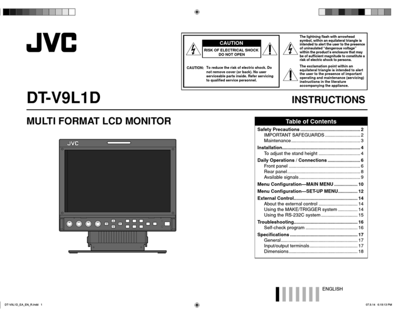
JVC TM-H1750CG/E User manual

TM-H1750CG
OPERATING INSTRUCTIONS
Jan. 2002 No. 51923
[ TM-H1750CG/E / TM-H1750CG/U ]
BEDIENUNGSANLEITUNG : FARB-VIDEO-MONITOR
MANUEL D’INSTRUCTIONS : MONITEUR VIDEO COULEUR
MANUALE DI ISTRUZIONI : MONITOR VIDEO A COLORI
INSTRUCCIONES : MONITOR DE VIDEO A COLOR
!"#$%&'(&)
INSTRUCTIONS
TM-H1750CG
COLOR VIDEO MONITOR
ESPAÑOL ITALIANO FRANÇAIS DEUTSCH ENGLISH
POWER
CHROMA MENU ASPECT
INPUT SELECT
SLOT
UNDER
SCAN COLOR
OFF BLUE
CHEC
PHASE
TM-H1750CG
BRIGHT
CONTRAST VOLUME/SELECT AB
CD
LCT1025-001A-H
1101-Y-U-JMT
For Customer Use:
Enter below the Serial No. which i located on the rear of the cabinet.
Retain thi information for future reference.
Pour l’usage du client:
Enter ci-de ou le numéro de érie qui e t itué ur l’arrière du coffret.
Con erver cette information pour une référence ultérieure.
Model No. :
Numéro de modèle : TM-H1750CG
Serial No. :
Numéro de érie :

TM-H1750CG
1-2 No.51923
ENGLISH
CONTENTS
SAFETY PRECAUTIONS................................................................................. 2
CONTROLS AND FEATURES ......................................................................... 4
CONTROLS AND FEATURES
(INPUT CARD: OPTIONAL)........................................
7
PREPARATION................................................................................................. 8
HOW TO HANDLE BASIC OPERATIONS ....................................................... 9
HOW TO USE THE MENU FUNCTIONS.........................................................11
HOW TO INITIALIZE THE SETTING.............................................................. 14
BASIC CONNECTION EXAMPLE.................................................................. 15
HOW TO USE EXTERNAL CONTROL .......................................................... 17
TROUBLESHOOTING.................................................................................... 18
SPECIFICATIONS .......................................................................................... 19
APPENDIX...................................................................................................... 20
SCREEN BURN
● It i not recommended to keep a certain till image di played on creen for a long time a well a di playing extremely bright
image on creen. Thi may cau e a burning ( ticking) phenomenon on the creen of cathode-ray tube. Thi problem doe
not occur a far a di playing normal video playback motion image .
3
Fu e
POWER CONNECTION
The power upply voltage rating of thi product i AC 120 V (For U.S.A. and Canada only) and AC 230 V (For European countrie
or United Kingdom), the power cord attached conform to the following power upply voltage and countrie . U e only the power
cord de ignated to en ure Safety and EMC regulation of each countrie .
Power cord
Power upply voltage : AC 120 V AC 230 V AC 230 V
Countrie : U.S.A. and Canada European countrie United Kingdom
Warning:
●
Do not u e the ame Power Cord for AC 120 V a for AC 230 V. Doing o may cau e malfunction, electric hock
or fire.
Note for the United ingdom power cord only
The plug on the United Kingdom power cord ha a built-in fu e. When replacing the fu e, be ure to u e only a correctly rated
approved type, re-fit the fu e cover.
(Con ult your dealer or qualified ervice per onnel.)
How to replace the fuse
Open the fu e compartment with the blade crew driver, and
replace the fu e.
(* An example i hown in the illu tration.)
In order to prevent any fatal accident cau ed by mi operation
or mi handling the monitor, be fully aware of all the following
precaution .
WARNINGS
To prevent fire or hock hazard, do not expo e thi
monitor to rain or moi ture. Dangerou high voltage
are pre ent in ide the unit. Do not remove the back
cover of the cabinet. When ervicing the monitor,
con ult qualified ervice per onnel. Never try to ervice
it your elf.
WARNING : THIS APPARATUS MUST
BE EARTHED.
PRECAUTIONS
● U e only the power ource pecified on the unit.
(120 V AC/230 V AC, 50 Hz/60Hz)
● When not u ing thi unit for a long period of time, or when
cleaning it, be ure to di connect the power plug from the
AC outlet.
● Do not allow anything to re t on the power cord. And do not
place thi unit where people will tread on the cord. Do not
overload wall outlet or power cord a thi can re ult in a
fire or electric hock.
● Avoid u ing thi unit under the following condition :
– in extremely hot, cold or humid place ,
– in du ty place ,
– near appliance generating trong magnetic field ,
– in place ubject to direct unlight,
– in badly ventilated place ,
– in automobile with door clo ed.
● Do not cover the ventilation lot while in operation a thi
could ob truct the required ventilation flow.
● When du t accumulate on the creen urface, clean it with
a oft cloth.
● Unplug thi unit from the AC outlet and refer ervicing to
qualified ervice per onnel under the following condition :
– when the power cord i frayed or the plug i damaged,
– if liquid ha been pilled into the unit,
– if the unit ha been dropped or the cabinet ha been
damaged,
– when the unit exhibit a di tinct change in performance.
● Do not attempt to ervice thi unit your elf a opening or
removing cover may expo e you to dangerou voltage or
other hazard . Alway refer ervicing to qualified ervice
per onnel.
● When replacement part are required, have the ervice
per onnel verify in writing that the replacement part he/
he u e have the ame afety characteri tic a the
original part . U e of manufacture’ pecified replacement
part can prevent fire, hock, or other hazard .
● Upon completion of any ervicing or repair work to thi unit,
plea e a k the ervice per onnel to perform the afety
check de cribed in the manufacturer’ ervice literature.
● When thi unit reache the end of it u eful life, improper
di po al could re ult in a picture tube implo ion. A k
qualified ervice per onnel to di po e of thi unit.
Thi monitor i equipped with a 3-blade grounding-type
plug to ati fy FCC rule. If you are unable to in ert the
plug into the outlet, contact your electrician.
Machine Noi e Information Ordinance 3. GSGV,
January 18, 1991: The ound pre ure level at the
operator po ition i equal or le than 70 dB(A)
according to ISO 7779.
Improper operation , in particular alternation of high
voltage or changing the type of tube may re ult in x-ray
emi ion of con iderable do e. A unit altered in uch a
way no longer meet the tandard of certification, and
mu t therefore no longer be operated.
FCC INFORMATION (U.S.A. only)
CAUTION: Change or modification not approved by
JVC could void the u er' authority to operate the
equipment.
NOTE: Thi equipment ha been te ted and found to
comply with the limit for a Cla B digital device,
pur uant to Part 15 of the FCC Rule . The e limit are
de igned to provide rea onable protection again t
harmful interference in a re idential in tallation. Thi
equipment generate , u e and can radiate radio
frequency energy and, if not in talled and u ed in
accordance with the in truction , may cau e harmful
interference to radio communication . However, there i
no guarantee that interference will not occur in a
particular in tallation. If thi equipment doe cau e
harmful interference to radio or televi ion reception,
which can be determined by turning the equipment off
and on, the u er i encouraged to try to correct the
interference by one or more of the following mea ure :
– Reorient or relocate the receiving antenna.
– Increa e the eparation between the equipment and
receiver.
– Connect the equipment into an outlet on a circuit
different from that to which the receiver i connected.
– Con ult the dealer or an experienced radio/TV
technician for help.
2
SAFETY PRECAUTIONS
Notice (U.S.A. only)
Thi product utilize both a Cathode Ray Tube (CRT) and
other component that contain lead. Di po al of the e
material may be regulated in your community due to
environmental con ideration . For di po al or recycling
information plea e contact your local authoritie , or the
Electronic Indu trie Alliance: <http://www.eiae.org.>
TM-H1750CG
1-3
No.51923
ENGLISH
Input card slot (SLOT)
Optional input card can be in talled in thi lot. Input
card are not provided when you purcha e thi monitor.
REMOTE (external control) terminal
Connect thi terminal to an external control unit to enable
remote operation of the monitor.
Refer to the HOW TO USE EXTERNAL CONTROL on
page 17 for more detail .
Video A terminals [VIDEO A IN/OUT]
Video ignal input (IN) and output (OUT) terminal .
The output terminal i bridge-connected.
IN : Video ignal input terminal
OUT : Bridge-connected video ignal output terminal
Notes:
* For corre ponding audio ignal , u e the AUDIO A
terminal
q
.
* Al o refer to BASIC CONNECTION EXAMPLE
on page 15.
Video B terminals [VIDEO B IN/OUT]
Video ignal input (IN) and output (OUT) terminal .
The output terminal i bridge-connected.
IN : Video ignal input terminal
OUT : Bridge-connected video ignal output terminal
Notes:
* For corre ponding audio ignal , u e the AUDIO B
terminal
w
.
* Al o refer to BASIC CONNECTION EXAMPLE on
page 15.
Video B (Y/C) terminals [VIDEO B Y/C IN/OUT]
Y/C (S-video) ignal input (IN) and output (OUT) termi-
nal . The output terminal i bridge-connected.
IN :Y/C- eparated (S-video) video ignal input
terminal
OUT :Bridge-connected Y/C- eparated (S-video) ignal
output terminal.
REAR VIEW
<Rear Panel>
5
Notes:
* For corre ponding audio ignal , u e the AUDIO B
terminal
w
.
* When both VIDEO B terminal are connected (input) at
the ame time, the Y/C terminal ha priority.
* Al o refer to BASIC CONNECTION EXAMPLE
on page 16.
Audio A terminals [AUDIO A IN/OUT]
Input (IN) and output (OUT) terminal for the audio ignal
corre ponding to the VIDEO A terminal
*
.
The output terminal i bridge-connected.
IN : Audio ignal input terminal
OUT : Bridge-connected audio ignal output terminal
Notes:
* For corre ponding video ignal , u e the VIDEO A
terminal
*
.
* Al o refer to BASIC CONNECTION EXAMPLE
on page 15 and 16.
Audio B terminals [AUDIO B IN/OUT]
Input (IN) and output (OUT) terminal for the audio
ignal corre ponding to the VIDEO B terminal
(
or
VIDEO B (Y/C) terminal
)
.
The output terminal i bridge-connected.
IN : Audio ignal input terminal
OUT : Bridge-connected audio ignal output terminal
Notes:
* For corre ponding video ignal , u e the VIDEO B
terminal
(
or VIDEO B (Y/C) terminal
)
.
* Al o refer to BASIC CONNECTION EXAMPLE
on page 15 and 16.
18 16
17
19
20
21
22
VIDEO A
REMOTE
SLOT
AUDIO A
AUDIO B
VIDEO B
IN OUT
IN
IN
IN
OUT
OUT
IN OUT
Y/C
OUT
VIDEO A
AUDIO A
AUDIO B
VIDEO B
IN OUT
IN
IN
IN
OUT
OUT
IN OUT
Y/C
OUT
16
17
18
19
20
21
22
Tally lamp
Light when the tally control ignal i ON. The tally control
ignal i input through the REMOTE (external control)
remote terminal. For detail , refer to Page 17.
Chroma/Phase button
[ CHROMA/ PHASE]
Pre thi button to activate the picture color den ity
adju tment mode or picture hue adju tment mode. Each
time you pre the button, the adju tment item change .
Picture color density
f
Picture hue
Adju t the value with the VOLUME/SELECT button
4
.
Al o u ed a a control button in the menu function mode.
Contrast/Brightness button
[CONTRAST / BRIGHT ]
Pre thi button to activate the picture contra t adju tment
mode or picture brightne adju tment mode. Each time
you pre the button, the adju tment item change .
Picture contrast
f
Picture brightness
Adju t the value with the VOLUME/SELECT button
4
.
Al o u ed a a control button in the menu function mode.
Volume/Select buttons
[VOLUME/SELECT – +]
Adju t the peaker volume. Al o u ed a a control
button in the menu function mode.
Menu button [MENU]
Di play and di appear the <MENU> creen.
Pre ing the CHROMA/PHASE button
2
with the Menu
button depre ed will di play the <SET-UP MENU>
creen.
Under Scan button [UNDER SCAN]
Reduce the creen ize to di play the entire image.
Pre the button again to cancel Under Scan.
When elected, the Under Scan button light .
Color Off button [COLOR OFF]
Cut color ignal to di play a black and white image.
Pre the button again to re tore the original color.
When elected, the COLOR OFF button light .
Note:
●Thi function i invalid with RGB input.
CONTROLS AND FEATURES
FRONT VIEW
<Front Panel>
Blue Check button [BLUE CHEC ]
Cut red and green ignal component . Only blue ignal
component are hown. Pre the button again to
re tore the normal image.
When elected, thi button light .
Aspect button [ASPECT]
Pre thi button to change the a pect ratio from 4:3 to
16:9.
Input A (VIDEO) button [INPUT SELECT A]
Select the video and audio ignal input to the VIDEO A
*
and AUDIO A
q
terminal on the rear panel. The
button light when elected.
Input B (VIDEO Y/C) button [INPUT SELECT B]
Select the video and audio ignal input to the VIDEO B
(
or VIDEO B (Y/C)
)
and AUDIO B
w
terminal on
the rear panel. The button light when elected.
Note:
●The VIDEO B terminal include a video terminal (BNC
connector) and a Y/C terminal (mini-DIN 4-pin connector).
The Y/C (S-video) terminal ha priority.
Input C/D (Slot) buttons [INPUT SELECT C/D
(SLOT)]
Select the ignal to be input via the input card in talled
in the rear panel card lot .
C, D: Select the image from the input card in the lot.
For detail on input connector and u ing the INPUT
SELECT button, refer to page 7.
Power indicator
Unlit : The main power i OFF.
Orange : The main power i ON, but the monitor’ power
i OFF (in the tand-by mode).
Green : The main power i ON, and the monitor’ power
i ON (in the normal operation mode).
Power switch [POWER ]
Pre the power witch to turn the monitor’ power ON or
OFF when the main power i ON.
Note:
●When RUSH DELAY i et to SLOW, it take about
three econd before power i actually upplied after
the power witch i pre ed.
Speaker
A built-in peaker i located in ide the right ide panel
when the monitor i viewed from the front.
1
2
3
4
5
6
7
8
9
10
11
12
13
14
4
15
POWER
CHROMA MENU ASPECT
INPUT SELECT
SLOT
UNDER
SCAN COLOR
OFF BLUE
CHEC
PHASE
TM-H1750CG
BRIGHT
CONTRAST VOLUME/SELECT AB
CD
1
48 9 10 11 12 1413
7
POWER
CHROMA MENU ASPECT
INPUT SELECT
SLOT
UNDER
SCAN COLOR
OFF BLUE
CHEC
PHASE BRIGHT
CONTRAST VOLUME/SELECT AB
CD
2356
15

TM-H1750CG
1-4 No.51923
ENGLISH
Video input/output terminals
Input (IN) and output (OUT) terminal for component
(color deference) or RGB ignal .
The IN and OUT terminal are bridge-connected.
(When no cable i connected to the OUT terminal, the
input ignal i automatically terminated.)
Select component ignal : pre INPUT SELECT C button
Select RGB ignal :pre INPUT SELECT D button
Synchronized signal input/output terminals
Input (IN) and output (OUT) terminal for the vertical,
horizontal or complex ynchronized ignal .
The ynchronized ignal from the e terminal have
priority over other terminal . When no ynchronized ignal
i input to the e terminal , the ynchronized ignal from
the video input/output terminal (G/Y terminal ) i valid.
The IN and OUT terminal are bridge-connected.
(When no cable i connected to the OUT terminal, the
input ignal i automatically terminated.)
External sync is available with RGB input only. G on
SYNC cannot be u ed with RGB input.
Audio input/output terminals
Input (IN) and output (OUT) terminal for audio ignal .
The IN and OUT terminal are bridge-connected.
Connection terminal (to a Color Video Monitor)
Attach to the connection terminal of your color video
monitor.
1
CONTROLS AND FEATURES
(INPUT CARD: OPTIONAL)
COMPONENT/RGB INPUT CARD (OPTIONAL:
IF-C01COMG)
B/P
B
/B-Y
G/Y
OUTIN
OUTIN
R/P
R
/B-Y
OUTIN
VD
OUTIN
HD/C
S
OUTIN
OUTIN
AUDIO
OUT
IN
1
2
3
4
Compatible ignal format :
480/50i, 480/60i
2
3
4
SDI INPUT CARD (OPTIONAL: IF-C01SDG)
AUDIO 2
AUDIO 1
OUT
IN
SWITCHED
OUT
SDI 1
SDI 2
IN
IN
1
2
3
4
Output terminal for a selected component
serial digital signal
Output terminal for a elected digital ignal (the input
di played on the creen). The output ignal i cable-
compen ated.
NOTE: When the monitor’ main power i OFF, no digital
ignal i output.
In the tandby mode, ignal from the SDI 1 connector
are output.
Input terminals for component serial digital
signals
Input terminal for the digital ignal.
Select SDI 1 : pre INPUT SELECT C button
Select SDI 2 : pre INPUT SELECT D button
Audio input/output terminals
Input (IN) and output (OUT) terminal for the analog
ignal corre ponding to SDI 1 and SDI 2.
NOTE: Thi input card cannot decode audio data even if
contained in the input digital ignal.
Connection terminal (to a Color Video
Monitor)
Attach to the connection terminal of your color video
monitor.
1
Compatible ignal format : 480/60i, 480/50i
Note:
●The optional input card hown below cannot be u ed.
U ing any of the e card will void your warranty and may
re ult in damage or malfunction.
*Video input card (IF-C01PNG)
*HD-SDI input card (IF-C01HSDG)
2
3
4
7
24 23
25
25
25
VIDEO A
REMOTE
SLOT
AUDIO A
AUDIO B
VIDEO B
IN OUT
IN
IN
IN
OUT
OUT
IN OUT
Y/C
OUT
REAR VIEW
<Rear Panel>
CONTROLS AND FEATURES
(cont’d)
6
Main power switch
Pre the witch to turn the main power ON or OFF. When
the main power i ON, the power lamp on the front panel
light in orange and the monitor enter the tand-by
mode.
I : ON : OFF
AC inlet [AC IN]
Power input connector. Connect the provided AC power
cord
t
to an AC outlet (120 V AC or 230 V AC,
50 Hz/60 Hz).
To AC outlet
(230 V AC,
50 Hz/60 Hz)
For the United Kingdom
For Europe
23 Power cord
Connect the provided power cord (120 V AC or
230 V AC, 50 Hz/60 Hz) to the AC IN connector
r
.
Caution:
In North America (USA and Canada), thi monitor come
with one power cable. In Europe and the United King-
dom, two power cable are provided (one for u e in
continental European countrie and the other for the UK).
Be ure to u e the power cable that i appropriate for the
AC outlet u ed in your region. If none of the power
cable provided i uitable, plea e contact your dealer or
qualified ervice per onnel to obtain the correct type of
power cable.
To AC outlet
(120 V AC,
50 Hz/60 Hz) For U.S.A. and Canada
24
25

TM-H1750CG
1-5
No.51923
ENGLISH
PAL
VOLUME : 20
PHASE : 00
+
–
INPUT
SELECT
buttons
Items VOLUME/SELECT button
–+
CHROMA lighter deeper
(Chroma)
PHASE reddi h greeni h
(Pha e)
CONTRAST lower higher
(Contra t)
BRIGHT darker brighter
(Brightne )
STATUS indication
(PAL or NTSC)
00 ~ 50
–40 ~ +40
HOW TO HANDLE BASIC
OPERATIONS
BASIC OPERATION
PICTURE ADJUSTMENT
1. Press the main power switch to turn on the power.
2. Press the POWER switch to turn on the power.
ON :Power turn ON. (Power indicator: lit)
Green :The main power i ON, and the monitor’
power i ON (in the normal operation mode).
OFF :Power turn OFF. (Power indicator: unlit)
Orange :The main power i ON, but the monitor’
power i OFF (in the tandby mode)
Unlit :The main power i OFF.
3. Press the INPUT SELECT buttons to choose input.
Select video/audio ignal input to terminal on the rear
panel. The elected button light in green.
4. Press the VOLUME/SELECT buttons to adjust the
speaker volume.
Pre thi button to di play the peaker volume level on the
creen.
+ : The Built-in peaker volume i increa ed. (00 = 50)
– : The Built-in peaker volume i decrea ed. (50 = 00)
* Screen indication will di appear about 10 econd after operating.
* The on- creen di play goe off when you pre MENU button.
1. Press select buttons corresponding to the item
you want to adjust.
The item you elect i di played on the creen.
1
Chorma control : Pre the CHROMA/PHASE button once.
2
Pha e control : Pre the CHROMA/PHASE button twice.
3
Contra t control : Pre the CONTRAST/BRIGHT button once.
4
Brightne control : Pre the CONTRAST/BRIGHT button twice.
* Pre ing the CHROMA/PHASE button and CONTRAST/BRIGHT button
alternately while the item i hown on creen re tore the previou tatu .
When no item i hown on creen, CHROMA and CONTRAST have priority.
* Screen indication will di appear about 10 econd after operating.
* The on- creen di play goe off when you pre MENU button.
About the STATUS indication
● With the COLOR SYSTEM etting et
to AUTO mode, when you turn on the
power or elect input , the color
y tem indication appear for about
3 econd on the creen while PAL or
NTSC ignal are being detected.
It doe not appear when receiving a
B/W ignal or when no ignal i input.
Refer to page 11 for more information
about COLOR SYSTEM etting and
page 12 for more information about
STATUS indication etting.
Notes:
● Pha e control i effective only in the
NTSC color y tem mode.
● Chroma control i not effective when
receiving RGB and B/W or when no
ignal i input. (Except when a
component ignal i input.)
● When CHROMA i adju ted to “–40,”
the picture become le colorful.
● “NO EFFECT” i di played (for about
3 econd ) when your elected
function ha no effect.
● To change the di play po ition on
creen, et UPPER or LOWER with
ADJ. BAR POSI.
2. Adjust with the VOLUME/SELECT buttons.
+
–
9
POWER
INPUT SELECT
SLOT
AB
CD
VOLUME/SELECT
CHROMA
PHASE BRIGHT
CONTRAST
VOLUME/SELECT
Terminals on the rear panel
Video signal input Audio signal input
1
Input A VIDEO A terminal AUDIO A terminal
(VIDEO)
2
Input B
VIDEO B terminal AUDIO B terminal
(VIDEO/Y/C)
PHASE : 00
UPPER
LOWER
VIDEO B (Y/C) terminal
3
Input C
4
Input D Refer to page 7 for detail about the input terminal
on each card and the INPUT SELECT button.
Note: The Y/C (S-video) terminal ha priority.
VIDEO A
REMOTE
SLOT
VIDEO B
IN OUT
IN
IN
OUT
Y/C
VIDEO A
REMOTE
SLOT
VIDEO B
IN OUT
IN
IN
OUT
Y/C
1. Turn off the Color Video Monitor’s main power and unplug the power cable
from the AC outlet.
2. Unscrew the screws and remove the slot cover from the slot (on the rear side
of the monitor) in which you are going to install the card.
3. Insert the Input Card’s board (green-colored) into the slot, fitting the board into
the guide rails on the top and bottom of the slot.
4. Push the Input Card in so that its front panel touches the monitor’s rear panel.
5. Secure the Input Card by replacing the screws removed in Procedure 2.
INSTALLING THE INPUT CARD
Slot cover
Fit the board to
the guide rail .
Rear ide of the TM-H1750CG
color video monitor
Knob
Input card (the illu tration
hown i of the IF-C01COMG)
Guide rail
Knob
NOTE :Do not touch the terminal connected to the monitor or board pattern.
Do not remove lot cover from the monitor’ lot if they are not in u e.
PREPARATION
8
VIDEO A
REMOTE
SLOT
VIDEO B
IN OUT
IN
IN
OUT
Y/C

TM-H1750CG
1-6 No.51923
ENGLISH
EXIT
CHROMA MENU
PHASE BRIGHT
CONTRAST VOLUME/SELECT
EXIT
CHROMA MENU
PHASE BRIGHT
CONTRAST VOLUME/SELECT
<MENU >
‰APERTURE : 00
ADJ. BAR POSI. :
LOWER
COLOR TEMP. : 6500
COLOR SYSTEM : AUTO
COMP. LEVEL : 00
RUSH DELAY : STD
Menu items Purpose Setting range
APERTURE Picture aperture level
ADJ.BAR POSI Volume bar po ition
COLOR TEMP. Color temperature of white
balance
COLOR SYSTEM Color y tem
COMPO. LEVEL* Component level
RUSH DELAY Delay time
Front panel Function Contents
button displayed
+ Increa e (to max. value)
4
Forward the etting value
– Decrea e (to min. value)
1
Rever e the etting value
VOLUME/
SELECT (–)
VOLUME/
SELECT (+)
Front panel Function Contents
button displayed
CHROMA/ Forward election mark (
4
)
PHASE
CONTRAST/ Rever e election mark (
4
)
BRIGHT
Front panel Function Contents
button displayed
MENU EXIT Quit (or Relea e) the <MENU>
creen
1
23
4
HOW TO USE THE MENU FUNCTIONS
• APERTURE • COLOR SYSTEM
• ADJ. BAR POSI. • COMPO. LEVEL*
• COLOR TEMP. • RUSH DELAY
You can et the following menu item .
Set them depending on your need .
1. Press the MENU button.
The <MENU> creen i di played.
* The on- creen di play goe off automatically after about five
minute with operation performed.
2. Press the CHROMA/PHASE or CONTRAST/BRIGHT
button to select MENU items.
A election mark (
4
) i put next to the elected item.
APERTURE
ADJ. BAR POSI.
COLOR TEMP.
COLOR SYSTEM
COMPO. LEVEL*
RUSH DELAY
3. Press the VOLUME/SELECT buttons to set.
4. If you want to set the other menu items, repeat
procedures 2 and 3.
5. Press the MENU button to quit.
1
Selection mark (
4
): Indicate the
menu item you elect.
2
Menu item: Menu item you can
elect.
3
Setting di play: Indicate the current
etting (value).
4
Function di play: The function of
the front panel button (5 button on
the left) corre pond to the function
di played.
The upper creen; when etting
“UPPER” in “ADJ. BAR POSI.”
The lower creen; when etting
“LOWER” in “ADJ. BAR POSI.”
<MENU> creen
<Front panel button >
Function
Contents
displayed
Forward the menu item.
Rever e the menu item.
– Lower the adju tment
value. (to the minimum)
+ Rai e the adju tment
value. (to the maximum)
4
Forward the etting value.
1
Rever e the etting value.
EXIT Exit the <MENU> creen.
DISPLAY AND SELECTION IN THE MENU>
SCREEN MODE (SETTING)
MENU
CHROMA
PHASE BRIGHT
CONTRAST
VOLUME/SELECT
MENU
11
LOWER UPPER
6500 9300
AUTO NTSC AUTO PAL
STD. SLOW
* For normal u e, leave the COLOR SYSTEM etting to AUTO.
If reception i un ati factory in AUTO po ition, et it to the appropriate color y tem mode (NTSC or PAL).
* COMPO. LEVEL i di played only with COMPONENT (SDI) input. (Shown with INPUT-C and INPUT-D
except for RGB input.)
BRIGHT : 00
<ADJ. BAR POSI> creen
<Front panel button >
BRIGHT : 00
UPPER
LOWER
00 +01 +39 +40
••••••••••••
–40 –39 –01 00 +1 +9 +10
••••
10
HOW TO HANDLE BASIC
OPERATIONS
(cont’d)
VIDEO SIGNAL CONTROLS
U e the e button for video ignal control.
UNDER SCAN
Pre the UNDER SCAN button to reduce the ize of di play area o that the whole
picture i di played on creen. U e to check the picture frame.
COLOR OFF
To di play a black and white picture, pre the COLOR OFF button to input the lumi-
nance ignal only. U e to check noi e in the luminance ignal or for white balance
adju tment.
Note:
●No effect with RGB input.
BLUE CHEC
Input the tandard color-bar ignal for your TV y tem and di play it on the creen.
When the BLUE CHECK button i pre ed, the red and green ignal are cut and only
the blue ignal i di played. The BLUE CHECK function adju t and check CHROMA
(COLOR) GAIN and PHASE.
Make ure that COMPO. LEVEL ha been initialized when a component ignal i input.
[Procedure]
1. Input the tandard color-bar ignal for your TV y tem and di play it on the creen.
2. Pre the BLUE CHECK button.
3. Pre the CHROMA button to adju t the chroma o that the blue bar on the left and
right ide of the creen have the ame brightne .
4. (Only when an NTSC ignal i input) Pre the PHASE button to adju t the pha e o
that the two blue bar at the center of the creen have the ame brightne .
5. (Only when an NTSC ignal i input) Repeat procedure 3 and 4 for the adju tment o
that all four blue bar on the creen have the ame brightne .
When you have fini hed making the adju tment, pre the BLUE CHECK button to
deactivate.
Initializing COMPO. LEVEL (when a component signal is input)
with the IF-C01COMG component/RGB input card inserted
When a component ignal i input, be ure to adju t (initialize) the COLOR off et in
COMPO. LEVEL.
[Procedure]
1. Input the tandard color-bar ignal for your TV y tem and di play it on the creen.
2. Pre the BLUE CHECK button.
3. Select COMPO. LEVEL in the <MENU> creen and then adju t it with VOLUME +/–
button o that the blue bar on the left and right ide of the creen have the ame
brightne .
4. Quit the <MENU> creen and pre the BLUE CHECK button.
5. Make ure that the blue bar on the left and right ide of the creen have the ame
brightne .
6. Repeat procedure 3, 4 and 5 for the adju tment o that the blue bar on the left and
right ide of the creen have the ame brightne .
Blue
Blue
Blue
Blue
Blue
Blue
Blue
Blue

TM-H1750CG
1-7
No.51923
ENGLISH
Set-up menu items Purpose Settings
PICTURE SUB ADJ. Image ub adju tment Select CONTRAST/BRIGHT/CHROMA/PHASE. The
elected etting creen i hown. Select the function di play for
adju tment.
CONTRAST Adju t contra t.
BRIGHT Adju t brightne .
CHROMA Adju t color den ity. *1
PHASE Adju t hue. *1
H. POSITION Adju t the horizontal po ition of the
creen (+: Horizontal po ition hift
to the right/-: Horizontal po ition hift to
the left)
V. POSITION Adju t the vertical po ition of the creen
(+: Vertical po ition move up/-: Vertical
po ition move down)
WHITE BALANCE Adju t the white balance. Select the drive (DRV) or cut off (CUTO) adju tment. The elected
etting creen i hown. Select the function di play for adju tment.
DRIVE R. DRIVE Adju t red level.
B. DRIVE Adju t blue level.
CUT OFF R. CUT OFF Adju t red cut off.
G. CUT OFF Adju t green cut off.
B. CUT OFF Adju t blue cut off.
CONTROL LOCK Set the operation button on the front
panel to control lock mode.
STATUS DISPLAY Set the tatu di play of the color y tem.
REMOTE SYSTEM Set the external control function method. *2
INPUT REMOTE Set external control of input election.
(Shown only when REMOTE SYSTEM i *2
et to MAKE.)
4. To set the other set-up menu items, repeat the
procedures 2 and 3.
5. Press the MENU button to quit.
Notes:
● When the CONTROL LOCK function i
et to ON, pre ing operation button
on the front panel will di play the
me age “CONTROL LOCK ON!” on
the creen for about 3 econd .
● The CONTROL LOCK function i
maintained even when the power i
turned off.
● To turn off the CONTROL LOCK
function, while holding the MENU button
pre the CHROMA/PHASE button.
Then et the CONTROL LOCK function
to OFF.
● Even when the CONTROL LOCK
function i et to ON, the following
operation are available:
– Power Switch operation
– Volume control with the VOLUME/
SELECT button
– Di play or di appear of the <SET-UP
MENU> creen.
● The STATUS DISPLAY function can be
et to di play (ON) or not di play (OFF)
the pre ent color y tem when the
power i turned on or the input ignal i
changed. Refer to page 9 for more
information.
●When REMOTE SYSTEM i et to
MAKE and any one of the INPUT A to D
button , the UNDER SCAN button,
COLOR OFF button or the ASPECT
button i pre ed, “REMOTE ON!”
appear on creen for about 3 econd .
(Not hown with CONTROL LOCK et
to ON.)
●When REMOTE SYSTEM i et to
TRG, the front panel control can be
operated.
●INPUT REMOTE and REMOTE
SYSTEM are enabled when REMOTE
ENABLE i et to ON.
Front panel Function Contents
button displayed
MENU EXIT Quit (or Relea e) the <MENU>
creen
MENU
13
–5 •••–01 00 +1 •••+5
–5 •••–01 00 +1 •••+5
OFF ON
OFF ON
MAKE TRG.
A–DA/B
–10 –9 –01 00 +01 +09 +10
••••
–20 –19 –01 00 +01 +19 +20
••••
*1 May not be hown depending on the type of ignal input.
*2 Refer to HOW TO USE EXTERNAL CONTROL on page 17 for more detail .
Note:
Setting De cription
MAKE Make contact y tem: Control the function with H and L ( hort-
circuit or open 15th terminal (GND)).
TRG. Trigger y tem: Control the function by hort-circuiting ( hort-
circuit or open 15th terminal (GND)) with pul e (about 1 ec.)
A-D Switche the input by hort-circuiting a pecified ignal line in
INPUT A, B, C, or D.
A/B Switche between INPUT A and INPUT B with D- ub pin 2.
(Al o, refer to HOW TO USE EXTERNAL CONTROL on page 17.)
–10 –9 –01 00 +01 +09 +10
••••
–10 –9 –01 00 +01 +09 +10
••••
–10 –9 –01 00 +01 +09 +10
••••
–20 –19 –01 00 +01 +19 +20
••••
–20 –19 –01 00 +01 +19 +20
••••
–20 –19 –01 00 +01 +19 +20
••••
–20 –19 –01 00 +01 +19 +20
••••
HOW TO USE THE MENU
FUNCTIONS
(cont’d)
12
EXIT
CHROMA MENU
PHASE BRIGHT
CONTRAST VOLUME/SELECT
DISPLAY AND SELECTIONS IN THE SET-UP
MENU> MODE (SETTING)
• PICTURE SUB ADJ. • WHITE BALANCE • REMOTE SYSTEM
• H. POSITION • CONTROL LOCK • INPUT REMOTE
• V. POSITION • STATUS DISPLAY
You can et the following et-up menu item .
1. While pressing the MENU button, press the
CHROMA/PHASE button.
The <SET-UP MENU> creen i di played.
* The on- creen di play goe off automatically after about five
minute with operation performed.
2. Press the CHROMA/PHASE or CONTRAST/BRIGHT
button to select the desired menu item.
A election mark (
4
) i put next to the elected item.
3. Press the VOLUME/SELECT buttons to set.
●For WHITE BALANCE item , elect the CUT OFF or DRIVE
etting creen, then elect the function di play for adju tment.
●Pre the EXIT (MENU) button to return to the <SET-UP
MENU> creen.
Notes:
<SET-UP MENU> creen
<Front panel button >
1
Selection mark (
4
): Indicate the
menu item you elect.
2
Menu item: Menu item you can
elect.
3
Setting di play: Indicate the
current etting (value).
4
Function di play: The function of
the front panel button (5 button
on the left) corre pond to the
function di played.
Function
Contents
displayed
Forward the menu item.
Rever e the menu item.
– Lower the adju tment
value. (to the minimum)
+ Rai e the adju tment
value. (to the maximum)
4
Forward the etting value.
1
Rever e the etting value.
EXIT Exit the <MENU>
creen.
DRV Select DRIVE adju tment.
CUTO Select CUT OFF
adju tment.
RB Adju t red and blue
ignal level.
RGB Adju t red, green and
blue ignal level.
Turn the ON-SCREEN
di play on or off. (Thi
DISP function i effective only
in the DRIVE or CUT OFF
adju tment mode.)
Front panel Function Contents
button displayed
CHROMA/
Forward election mark (
4
)
PHASE
CONTRAST/
Rever e election mark (
4
)
BRIGHT
Front panel Function Contents
button displayed
+ Increa e (to max. value)
4
Forward the etting value
CUTO Select CUT OFF etting creen
– Decrea e (to min. value)
1
Rever e the etting value
DRV Select DRIVE etting creen
VOLUME/
SELECT (–)
VOLUME/
SELECT (+)
●Parameter for H. POSITION and V. POSITION can be et eparately depending on
the ignal (Input A (VIDEO), Input B (VIDEO), Input C or Input D) elected with the
input elect button on the front panel.
Select the required video input with the input elect button on the front panel in
advance.
●WHITE BALANCE can be et independently at 6500 or 9300 for the color temperature
value.
Set COLOR TEMP. to 6500 or 9300 on the <MENU> creen beforehand.
●INPUT REMOTE i hown when REMOTE SYSTEM i et to MAKE.
Notes:
<SET-UP MENU>
‰PICTURE SUB ADJ.
H. POSITION : 00
V. POSITION : 00
WHITE BALANCE
CONTROL LOCK : OFF
STATUS DISPLAY : ON
REMOTE SYSTEM : MAKE
INPUT REMOTE : A – D
1
23
4
PICTURE SUB ADJ.
H. POSITION
V. POSITION
WHITE BALANCE
CONTROL LOCK
STATUS DISPLAY
REMOTE SYSTEM
INPUT REMOTE
MENU
CHROMA
PHASE
CHROMA
PHASE BRIGHT
CONTRAST
VOLUME/SELECT

TM-H1750CG
1-8 No.51923
ENGLISH
VIDEO A
AUDIO A
AUDIO B
VIDEO B
IN OUT
IN
IN
IN
OUT
OUT
IN OUT
Y/C
OUT
BASIC CONNECTION EXAMPLE
Notes:
•
Before connecting your y tem, make ure that all unit are turned off.
•
The illu tration below how ome example of different connection . Terminal connection may differ depending on the component connected.
Be ure to refer to the in truction provided with the unit( ) you are connecting.
•
Each pair of input (IN) and output (OUT) terminal are bridge-connected.
•
If you’re not connecting any equipment to a bridged output (OUT) terminal, be ure not to connect any other cable to the bridged output (OUT)
terminal a thi will cau e the terminating re i tance witch to open (auto terminate function).
•
When making a bridge connection, connect the input (IN) and output (OUT) terminal on the monitor to eparate video component .
(For example, if both terminal are connected to the ame VCR, re onance may occur except during playback. Thi i cau ed by the ame video
ignal “looping” between the VCR , and i not a malfunction.)
•
Select the video input ignal (INPUT A(VIDEO) or INPUT B (VIDEO/Y/C)) with the INPUT SELECT button on the front panel. When both
VIDEO B terminal are connected (input) at the ame time, the Y/C terminal ha priority.
VIDEO A Connection Example (Select Input A (VIDEO))
VIDEO B (VIDEO) Connection
Example (Select Input B (VIDEO))
Video Camera
Video Monitor
VCR
Video Camera
Video Monitor
VCR
Video
(Video ignal cable)
Audio
(Audio ignal cable)
Video
(Video ignal cable)
Audio
(Audio ignal cable)
Audio
(Audio ignal cable)
Video
(Video ignal cable)
Video
(Video ignal cable)
Video Monitor
Video Monitor
VCR
: Signal Flow
15
Audio
(Audio ignal
cable)
14
Functions (Items) Initialization
(setting)
APERTURE 00
ADJ. BAR POSI LOWER
COLOR TEMP 6500
COLOR SYSTEM
AUTO
COMPO. LEVEL 00
RUSH DELAY STD
PICTURE SUB ADJ.
CONTRAST 00
BRIGHT 00
CHROMA 00
PHASE 00
H. POSITION 00
V. POSITION 00
WHITE BALANCE
R. CUT OFF 00
G. CUT OFF 00
B. CUT OFF 00
R. DRIVE 00
B. DRIVE 00
CONTROL LOCK OFF
STATUS DISPLAY ON
REMOTE SYSTEM MAKE
INPUT REMOTE A – D
CHROMA 00
PHASE 00
CONTRAST 00
BRIGHT 00
VOLUME 20
<SET–UP MENU> RESET
Are you ure ?
“Ye ” then <+>
“No” then <MENU>
Sorts
<MENU> creen
<SET-UP MENU> creen
Volume
HOW TO INITIALIZE THE
SETTING
SCREEN DISPLAY AND SELECTIONS IN THE
SET-UP MENU> RESET MODE
You can et <MENU> and <SET-UP MENU> creen item , picture adju tment item and
the volume level to their factory- et (initial) value .
1. Press the Power ( ) switch to turn the power
OFF (activate the standby mode).
The <SET-UP MENU> RESET creen i di played.
* The creen automatically di appear when no operation
i performed after about 5 minute .
Initial etting
<SET-UP MENU> RESET creen
2. While pressing both MENU button and CHROMA/
PHASE button, press the Power ( ) switch to turn
the power ON.
3. Setting
Initialization i required.
Initialization i not required.
Pre the VOLUME/SELECT [+] button.
* Initialization i completed, and the <SET-UP MENU>
RESET creen di appear .
Pre the MENU button.
* Initialization i aborted, and the <SET-UP MENU>
RESET creen di appear .
●The <SET-UP MENU> RESET creen will not be
di played if the MENU or CHROMA/PHASE button are
pre ed for a very hort time. Keep pre ing them until
the di play creen appear .
Note:
POWER
MENU
CHROMA
PHASE
POWER
MENU
VOLUME/SELECT
Picture adju tment

TM-H1750CG
1-9
No.51923
ENGLISH
HOW TO USE EXTERNAL
CONTROL
ABOUT EXTERNAL CONTROL
Thi monitor i provided with an external control terminal. MAKE (make contact) or TRG. (trigger) y tem can be elected.
(MAKE (make contact y tem): The function i controlled with H and L ( hort-circuit/open with the 15th pin GND).
(TRG. (trigger y tem): The function i controlled by hort-circuiting with pul e (for about 1 econd) ( hort-circuit/open with the
15th pin GND).
* The 14th pin (REMOTE ENABLE) i controlled with MAKE even though TRG. i elected.
Note:
●When thi monitor i externally controlled, the following button are di abled.
MAKE: INPUT-A to D, UNDER SCAN, COLOR OFF, ASPECT on the front panel.
*1: OFF tand for di connection, and ON tand for hort-circuit.
*2: When INPUT REMOTE in the et-up menu i et to A/B, H: INPUT A and L: INPUT B are et.
*3: When INPUT REMOTE in the et-up menu i et to A/B, pin not u ed hould not be connected.
*4: When INPUT REMOTE in the et-up menu i et to A/B, pin not u ed hould not be connected.
*5: When INPUT REMOTE in the et-up menu i et to A/B, pin not u ed hould not be connected.
*6: Do not connect.
*7: Setting REMOTE ENABLE to ON enable remote control from the REMOTE terminal.
*8: INPUT REMOTE etting in the et-up menu (REMOTE SYSTEM hown only when MAKE i elected.)
For the D- ub pin 2, 3, 4 and 5, 4-pin or 1-pin control can be et with INPUT REMOTE in the et-up menu.
•4-pin control: Switche input by hort-circuiting a pecified ignal line in INPUT A to D.
•1-pin control: Switche between INPUT-A and INPUT-B only with the 2nd pin of the D- ub connector. In thi ca e, INPUT-C and INPUT-D
cannot be elected.
Open (H): INPUT-A
Short-circuit (L): INPUT-B
NOTE : When more than two terminal are elected ( hort-circuited) from INPUT A through INPUT D, ignal input i prioritized
alphabetically (A, B, C, D).
To control INPUT A through INPUT D, we recommend u ing the interlock witch, which turn off a witch when another
witch i turned on.
The Names and Functions of Terminals
No. Names Functions Operations (OFF p[ ON) *1
1 TALLY Put on the tally lamp. Put off Put on
2 INPUT A Change the input to INPUT A Not change Change *2*8
3 INPUT B Change the input to INPUT B Not change Change *3*8
4 INPUT C Change the input to INPUT C Not change Change *4*8
5 INPUT D Change the input to INPUT D Not change Change *5*8
6 not u ed – – – *6
7 not u ed – – – *6
8 COLOR OFF Change the picture black-and-white. Not change Change
9 not u ed – – – *6
10 ASPECT Change the creen ratio to 16:9 4:3 16:9
11 UNDER SCAN Make the creen under- can Over- can Under- can
12 not u ed – – – *6
13 not u ed – – – *6
14 REMOTE ENABLE Make the external control from the Invalid Valid *7
REMOTE terminal valid or invalid
15 GND U ed a a ground terminal – –
Connections
Connect ( hort-circuit) the 15th terminal (GND) to each of the 1 t through 14th terminal in the
3-line 15-pin D- ub connector. The function of each terminal are li ted below.
1
2
3
10
8
9
6
7
11
12
13
14
15 4
5
17
VIDEO B (Y/C) Connection Example (Select Input B (Y/C))
VIDEO A
AUDIO A
AUDIO B
VIDEO B
IN OUT
IN
IN
IN
OUT
OUT
IN OUT
Y/C
OUT
Video Camera
Video Monitor
VCR
Y/C (S-video)
(Y/C (S-video) ignal cable)
Audio
(Audio ignal cable)
Audio
(Audio ignal cable)
Y/C (S-video)
(Y/C (S-video) ignal cable)
Video Monitor
VCR
BASIC CONNECTION EXAMPLE
(cont’d)
: Signal Flow
16

TM-H1750CG
1-10 No.51923
Problems
No power supply.
No picture with the
power on.
No sound.
Shaking picture.
No colors, wrong
color, or dark picture.
Unnatural, irregularly
colored, or distorted
picture.
Dark stripes appear
at the top and bottom
of the screen, picture
vertically squeezed.
The overall picture
size is too small.
Function buttons on
the front panel do not
function.
The INPUT SELECT
buttons do not
function.
Points to be checked
I the power plug loo ened or di connected?
I the main power turned OFF?
I the video ignal output from the connected
component?
I the input ignal elected properly?
I the video cable di connected?
I the audio ignal output from the connected
component?
I the volume output et to minimum?
I the audio cable di connected?
I the monitor clo e to a device generating a
trong magnetic field?
I the color y tem elected properly?
Ha the picture control etting (CONTRAST,
BRIGHT, CHROMA or PHASE) been changed?
I the monitor clo e to a peaker, magnet or any
other device generating a trong magnetic field?
I the a pect ratio et to 16:9?
Ha the UNDER SCAN button been pre ed o
the UNDER SCAN button light ?
Ha control of the button been locked? (Ha
the CONTROL LOCK function been et to ON?)
I input election under external control? (Ha
the REMOTE ENABLE function been et to
valid?)
Measures (Remedy)
Firmly in ert the power plug.
Turn the main power ON. (See page 6.)
Set the connected component correctly.
Select the required video ignal input with the
Input elect button. (See page 9.)
Connect the video ignal cable firmly.
(See page 15 and 16.)
Set the connected component correctly.
Adju t the peaker volume with the VOLUME/
SELECT button. (See page 9.)
Connect the audio ignal cable firmly.
(See pag 15 and 16.)
Move the device away from the monitor until the
picture tabilize .
Set COLOR SYSTEM in the <MENU> creen to
AUTO. (See page 11.)
Set each picture control to the tandard etting.
(See page 9.)
Pre the COLOR OFF button and BLUE CHECK
button to adju t. (See page 10.)
Move the device away from the monitor and turn
the monitor’ power off. Wait at lea t 30 minute ,
then turn the power on again.
Switch the a pect ratio to 4:3 with the ASPECT
button on the front panel.
Pre the UNDER SCAN button to turn off the
button. (See page 4.)
Set CONTROL LOCK in the <SET-UP MENU>
creen to OFF. (See page 12 and 13.)
Set REMOTE SYSTEM in the <SET-UP MENU>
creen to TRG. (See page 12 and 13.)
Set REMOTE ENABLE to OFF (invalid).
(See page 17.)
TROUBLESHOOTING
Solutions to common problems related to your monitor are described here. If none of the solutions presented here
solves the problem, unplug the monitor and consult a JVC-authorized dealer or service center for assistance.
The following are not malfunctions:
●When a bright till image ( uch a a white cloth) i di played for a long period, it may appear to be colored. Thi i due to the
tructure of the cathode ray tube and will be deleted when another image i di played.
●You experience a mild electric hock when you touch the picture tube. Thi phenomenon i due to a normal buildup of tatic
electricity on the CRT and i not harmful.
●The monitor emit a trange ound when the room temperature change uddenly. Thi i only a problem if an abnormality
appear on the creen a well.
●If two or more monitor are operated next to each other, their image may hake or be di torted. Thi phenomenon i due to
mutual interference; it i not a malfunction. Move the monitor away from each other until the interference di appear or turn
the power off on any monitor that i not being u ed.
18

TM-H1750CG
1-11
No.51923
ENGLISH
SPECIFICATIONS
Type : Color video monitor
Color system : PAL, NTSC (3.58)
Picture tube : 16-3/16" (41 cm) mea ured
diagonally,
90° deflection, in-line gun,
trio-dot type (pho phor dot-trio
pitch 0.27 mm)
Effective screen size : Width 12-7/8" (327.5 mm)
Height 9-5/8" (246.2 mm)
Diagonal 16-1/32" (407.1 mm)
Scanning frequency : (H) 15.734 kHz (NTSC)
15.625 kHz (PAL)
(V) 59.94 Hz (NTSC)
50 Hz (PAL)
Horizontal resolution : 750 TV line or more
Input terminals
VIDEO A : Compo ite video:
1 line, BNC connector x 2,
1 V(p-p), 75 Ω, negative ync
(bridge connection po ible,
auto termination)
VIDEO B : Compo ite video:
1 line, BNC connector x 2,
1 V(p-p), 75 Ω, negative ync
(bridge connection po ible,
auto termination)
Y/C- eparated:
1 line, mini-DIN 4-pin
connector x 2
Y: 1.0 V (p-p), 75 Ω
C (BURST): 0.286 V (p-p),
75 Ω (NTSC)
0.3 V (p-p), 75 Ω (PAL)
(bridge connection po ible,
auto termination)
AUDIO A : 1 line (monaural), RCA pin x 2
0.5 V(rm ), high-impedance
(bridge connection po ible)
AUDIO B : 1 line (monaural), RCA pin x 2
0.5 V(rm ), high-impedance
(bridge connection po ible)
REMOTE : Point-of-contact connection,
1 line
D- ub connector (15-pin, 3-line)
Audio power output : 1 W (monaural)
Built-in speaker : 8 cm round x 1
impedance of 8 Ω
Environmental
conditions : Operation temperature:
0°C – 40°C (32°F – 104°F)
Operation humidity:
20 % – 80 % (non-conden ing)
Power requirements : 120 V/230 V AC, 50 Hz/ 60 Hz
Power consumption : 1.2 A (120 V AC)/0.8 A (230 V
AC)
Dimensions : Width 15-5/8" (395 mm)
Height 13-1/4" (334 mm)
Depth 16-1/2" (418.1 mm)
Weight : 44.3 lb (20.1 kg)
Accessory : AC power cord
* Illustrations used in this manual are for explanatory purposes only. The appearance of the actual product may differ slightly.
* Dimensions and weight are approximate.
* E. & O. E. Design and specifications subject to change without notice.
19

TM-H1750CG
1-12 No.51923
82
,2!#
POWER
CHROMA MENU ASPECT
INPUT SELECT
SLOT
UNDER
SCAN COLOR
OFF BLUE
CHEC
PHASE
TM-H1750CG
BRIGHT
CONTRAST VOLUME/SELECT AB
CD
15-5/8 (395)
16-1/2 (418.1)
16-1/8 (407)
2-3/4 (68) 11-3/8 (286)
1/8 (3)
1/8 (3)
12-7/8 (327.5)*
11-3/8 (288)
ø7/8 (20)
9-5/8 (246.2)*
13-1/4 (334)
7 (175)
1/16
(1.5)
Dimensions
< Front View > < Side View >
* A teri k (
*
) are u ed to indicate front panel
dimen ion .
Unit : inch (mm)
●To u e the SWITCHED OUT terminal, the main power mu t be ON. (Unlike a bridged output, thi connector output relocked
digital ignal .)
●Signal output from the SWITCHED OUT terminal can be elected with INPUT-C (SDI-1) and INPUT-D (SDI-2) button on the
front panel (or remote control).
●When INPUT-A or INPUT-B i elected, thi terminal output the ignal la t elected. In the tandby mode, ignal from the
SDI 1 connector are output.
APPENDIX:CONNECTION EXAMPLES FOR THE
SDI INPUT CARD
Pin No. Signal
1 GND (Y)
2 GND (C)
3Y
4C
Y/C (Mini DIN 4 pin) terminal
specification
IN
Y/C
OUT
2
1
2
1
4
3
4
3
20
This manual suits for next models
2
Table of contents
Other JVC Monitor manuals

JVC
JVC DT-V2000SU - Dtv Monitor User manual

JVC
JVC TM-A130SU - Color Monitor User manual

JVC
JVC DT-V1900CG/E User manual

JVC
JVC DT-V9L3DY - Broadcast Studio Monitor User manual

JVC
JVC LT-50NQ7115A User manual

JVC
JVC KW-M875DBW User manual

JVC
JVC TM-H1900GU - Color Monitor User manual

JVC
JVC GD-V4200PZW - Plasma Display Quick start guide

JVC
JVC DT-G17E User manual

JVC
JVC TM-15L1D User manual