manuals.online logo
Brands
  1. Home
  2. •
  3. Brands
  4. •
  5. JVC
  6. •
  7. Monitor
  8. •
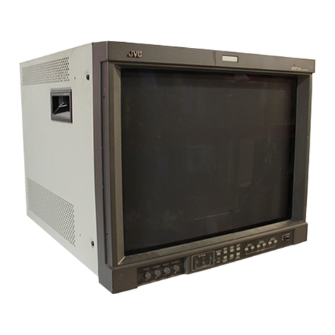
  9. JVC TM-H1950CG User manual

JVC TM-H1950CG User manual

No.51961
Jun. 2002
TM-H1950CG
1COPYRIGHT © 2002 VICTOR COMPANY OF JAPAN, LTD.
TM-H1950CG/E
TM-H1950CG/U
CONTENTS
!SPECIFICATIONS ・・・・・・・・・・・・・・・・・・・・・・・・・・・・・・・・
・・・・・・・・・・・・・・・・・・・・・・・・・・・・・・・・・・・・・・・・・・・・・・・・・・・・・・・・・・・・・・・・
・・・・・・・・・・・・・・・・・・・・・・・・・・・・・・・・・・・・・・・・・・・・・・・・・・・・・・・・・・・・・・・・
・・・・・・・・・・・・・・・・・・・・・・・・・・・・・・・・・・・・・・・・・・・・・・・・・・・・・・・・・・・・・・・・
・・・・・・・・・・・・・・・・・・・・・・・・・・・・・・・・・・・・・・
・・・・・・・・・・・・
・・・・・・ 2
★OPERATING INSTRUCTIONS (APPENDIX) ・・・・・・・・・・・・・・・・・・・・・・・・・・・・・・・・
・・・・・・・・・・・・・・・・・・・・・・・・・・・・・・・・・・・・・・・・・・・・・・・・・・・・・・・・・・・・・・・・
・・・・・・・・・・・・・・・・・・・・・・・・・・・・・・・・・・・・・・・・・・・・・・・・
・・・・・・・・・・・・・・・・・・・・・・・・・・・・・・・・
・・・・・・・・・・・・・・・・1- 1
!SAFETY PRECAUT IONS ・・・・・・・・・・・・・・・・・・・・・・・・・・・・・・・・
・・・・・・・・・・・・・・・・・・・・・・・・・・・・・・・・・・・・・・・・・・・・・・・・・・・・・・・・・・・・・・・・
・・・・・・・・・・・・・・・・・・・・・・・・・・・・・・・・・・・・・・・・・・・・・・・・・・・・・・・・・・・・・・・・
・・・・・・・・・・・・・・・・・・・・・・・・・・・・・・・・・・・・・・・・・・・・・・・・・・・・・・・・・・・・・・・・
・・・・・・・・・・・・・・・・・・・・・・・・・・・・・・・・ 3
!SPECIFIC SERVICE INSTRUCTIONS ・・・・・・・・・・・・・・・・・・・・・・・・・・・・・・・・
・・・・・・・・・・・・・・・・・・・・・・・・・・・・・・・・・・・・・・・・・・・・・・・・・・・・・・・・・・・・・・・・
・・・・・・・・・・・・・・・・・・・・・・・・・・・・・・・・・・・・・・・・・・・・・・・・・・・・・・
・・・・・・・・・・・・・・・・・・・・・・・・・・・・・・・・・・・・・・・・・・・・
・・・・・・・・・・・・・・・・・・・・・・ 6
!SERVICE ADJUSTMENTS ・・・・・・・・・・・・・・・・・・・・・・・・・・・・・・・・
・・・・・・・・・・・・・・・・・・・・・・・・・・・・・・・・・・・・・・・・・・・・・・・・・・・・・・・・・・・・・・・・
・・・・・・・・・・・・・・・・・・・・・・・・・・・・・・・・・・・・・・・・・・・・・・・・・・・・・・・・・・・・・・
・・・・・・・・・・・・・・・・・・・・・・・・・・・・・・・・・・・・・・・・・・・・・・・・・・・・・・・・・・・・
・・・・・・・・・・・・・・・・・・・・・・・・・・・・・・ 12
★STANDARD CIRCUIT DIAGRAM (APPENDIX) ・・・・・・・・・・・・・・・・・・・・・・・・・・・・・・・・
・・・・・・・・・・・・・・・・・・・・・・・・・・・・・・・・・・・・・・・・・・・・・・・・・・・・・・・・・・・・・・・・
・・・・・・・・・・・・・・・・・・・・・・・・・・・・・・・・・・・・・・・・・・・・・・
・・・・・・・・・・・・・・・・・・・・・・・・・・・・
・・・・・・・・・・・・・・2- 1
!PARTS LIST ・・・・・・・・・・・・・・・・・・・・・・・・・・・・・・・・
・・・・・・・・・・・・・・・・・・・・・・・・・・・・・・・・・・・・・・・・・・・・・・・・・・・・・・・・・・・・・・・・
・・・・・・・・・・・・・・・・・・・・・・・・・・・・・・・・・・・・・・・・・・・・・・・・・・・・・・・・・・・・・・・・
・・・・・・・・・・・・・・・・・・・・・・・・・・・・・・・・・・・・・・・・・・・・・・・・・・・・・・・・・・・・・・・・
・・・・・・・・・・・・・・・・・・・・・・・・・・・・・・・・・・・・・・・・・・
・・・・・・・・・・・・・・・・・・・・
・・・・・・・・・・ 39
BASIC CHASSIS
S1
SERVICE MANUAL
COLOUR VIDEO MONITOR
No.51961
TM-H1950CG
2
SPECIFICATIONS
Item Content
Dimen sio n (W×
××
×H×
××
×D) 440mm×375mm×496mm / 17-3/8”×14-7/8” ×19-5/8”
Mass 25.6kg / 56.3lbs
Colour system PAL / NTSC 3.58
Picture tube 19inch square type 49cm / 19” measured diagonall y
in-line gun, trio–dot type, dot pitch 0.27mm
Effective screen size 365.8mm×274.3mm (W×H) / 457 .2mm (Diagonal)
14-5/8”×10-7/8” (W ×H) / 18” (Diagonal)
Scanning frequency (H)15.734 kHz (NTSC)
15.625 kHz (PAL)
(V)59.94 Hz (NTSC)
50Hz (PAL)
Horizontal resolution 750TV line or mor e
Colour Temperat ure 6500K ; x = 0.313, y = 0.329
9300k ; x = 0.283, y = 0.297
Power requirements 230V AC, 50/60 Hz [TM-H1950CG /E]
120V AC, 50/60 Hz [TM-H1950CG /U]
High Voltage 24.7kV~27.3kv [at zero beam current]
Power consumption 0.9A [TM-H1950CG /E]
1.3A [TM-H1950CG /U]
Input / output terminal
Composite video signal BNC connector ×2, 1Vp-p, 75Ω, negative sync
1 bridge-connected output possible with automatic termination
Input A
Audio signal Mona ural, RCA pin×1, 500mV(rms)
High-impedance, 1-bridge-connected output posible
Composite video signal BNC connector ×2, 1Vp-p, 75Ω, negative sync
1 bridge-connected output possible with automatic termination
Y/C separate signal
(S input priority)
Mi ni Din 4
p
in ×2
,
1 brid
g
e-connected out
p
ut
p
ossible with automatic termination
Y : 1.0Vp-p, 75Ω
C : NTSC burst 0.286Vp-p, 75Ω
PAL bur st 0.3Vp-p, 75Ω
Input B
Audio si
g
nal Mona ural , RCA pin×1, 500mV(rms)
High-impedance, 1-bridge-connected output posible
Car d sl ot CO MPONENT / RGB input car d (IF-C01COM avai rable)
SD- SDI input card (IF-C01SD avairable)
Rem ote contro l in put D- sub 15pin
Make or TRG can switched in MENU
Audio power output 1W (Monaural)
Spe aker 8cm round×1, impedance 8Ω
Operation temperature 5℃~40℃(41~104°
F)
Operation humidity 20~80% (non-condensing)
Des ign & specifications are subject t o change without notice.
No. 51961
TM-H1950CG
3
SAFETY PRECAUTIONS
1. The d esign of t hi s p ro du ct c ont ai ns spec ial h ar dwar e, m an y
circu it s a nd co mp on ent s sp eci ally f or s afet y p urpos es. For
continued protection, no changes should be made to the
or igina l des ig n u nless a uth or ized in wri ti ng by t he m an uf actu re r.
Rep lacem en t par ts m ust be id ent ic al t o t hos e u sed in th e
or igina l circui t s. Se r vic e sho ul d be per fo rmed b y qu alified
p ers onn el o nl y.
2. Al te r ation s of th e desi g n o r circu itr y of th e p r odu cts s hou ld n ot
b e m ad e. A ny de sign al te ra tions o r ad ditio ns will vo id th e
manufacturer's warranty and will further relieve the
m anu fact ur er of r esp ons ib i li t y f or pe rs ona l in ju r y or p rope rt y
d am age r esu lt in g t heref r om .
3. M an y e lectrical an d m ech an ic al pa rt s in th e p r odu cts h ave
sp ecial saf ety-r elat ed c haract er is tics. Th ese charac teristics are
oft en n ot e vi d en t fr om visu al in spe cti on no r can t he pr ote ction
aff or de d by th em n ecess ar ily be o bta in ed b y usi ng
r eplac em ent co mp on ent s ra ted for h ig her vo l tag e, w a ttag e, etc.
Rep lacem en t p art s which h ave t he se sp eci al s afet y
ch ar acter istics a re i d entifie d in th e par ts l ist of S ervice m an ua l.
Electrical components having such features are identified
by shading on the schematics and by (!
!!
!) on the parts list
in S ervice manual . Th e u se of a su bst itu te re plac em en t which
does not have the same safety characteristics as the
r eco mm en de d re plac em en t pa rt sho wn i n the pa rts li st of
Se rvice ma nu al may c aus e sh ock, f ire, or o th er haz ar ds.
4. Use isola tio n tr an sforme r when hot c hass is .
The chassis and any sub-chassis contained in s ome products
ar e c on nect ed to on e si de of th e AC p ower li ne . An isol a tion
tr ansf or m er of ad equ ate cap acity sh ou ld be i nsert ed bet we en
th e p r odu ct and t he AC p ower su pp ly p oint whi le p er for ming
an y ser vice on so me pr o ducts wh en th e HOT ch assis is
exp ose d.
5. Do n't short between the LIVE side ground and ISOLATED
(NEUTRAL) side ground or EARTH side ground when
repairing.
So m e m od el's p ow er c ir cuit i s par t ly di f feren t in t he GN D. Th e
diff er enc e of t he GND is sh own by the LI VE : (") side GND,
th e ISO LATED( NEUTRA L) : (#) sid e GND an d EAR TH : ( $)
side GND . D on 't sho rt be twee n t he LIVE si d e GND a nd
ISO LATE D(NEUTRAL) side GND or EARTH side GND a nd
never measure with a meas uring apparatus (oscilloscope etc.)
th e LI VE side GND and ISO LATED(NEUTRA L) sid e G ND or
EARTH side GND at th e s ame time.
If above note will not be kept, a fuse or any parts will be brok en.
6. If an y re pa ir h as b ee n m ad e to th e ch assi s, i t is re comm end ed
th at t he B1 se tti n g sh ou ld b e chec ked or ad juste d (S ee
ADJUSTMENT OF B 1 POW E R SUPPL Y).
7. The hi g h vol t ag e a pp lied t o th e pi ctu re tu be mu st co nfo rm wi t h
that specified in Service manual. Excessive high voltage can
cau se an i ncr ea se in X-Ra y em ission , a rcin g and p ossi ble
com po ne nt d am ag e, th er ef or e op er ati o n un der excess ive hi gh
volta ge c ond it i ons sh ou ld be ke pt to a m in imu m, or sh ou l d be
pr eve nt ed. I f seve re arc in g occu rs, r emove th e AC p ower
immediately and determine the cause by visual inspection
( in cor r ect insta lla ti on , cr ac ked o r m elte d high vol tag e h ar ness,
p oor s ol de rin g, etc. ). T o ma in ta in the pr op er m inim um le vel of
soft X-Ray emission, components in the high voltage circuitry
includ ing the pi ctu r e tu be mu st be the exa ct r ep lacem en ts or
alte rn at i ves a ppr o ved b y th e ma nuf actu r er of th e co mp lete
pr od uct.
8. Do n ot c hec k high vol ta ge by d r awin g a n ar c. Us e a hi gh
volta ge m ete r or a h igh vol t age p ro be w ith a VT VM. Di sch arge
th e p ictu r e tu be bef or e a tte mp ti ng me ter co nne ction , b y
con nec ting a clip lead t o th e grou nd frame a nd con n ecting t he
oth er e nd of t he l ead th r oug h a 10 kΩ2W resist or to t he ano de
bu tto n.
9. W hen se rvi ce is r equ ir ed, ob ser ve th e o rig in al lea d dr ess.
Extr a p r ecau ti on sh ou l d be gi ven t o assu r e cor re ct lea d dr es s
in the h i gh volta ge c ir cu it ar ea . W her e a sh ort cir cuit ha s
occu rre d, th ose c omp on en ts th at ind ic ate evi den ce of
overheating should be replaced. Always use the
m anu fact ur er 's r eplace m ent com p on ents.
10 . Isolation Check
(Safety for Electrical Shock Hazard)
Af ter r e-a ssem bli ng th e pr od uct , al ways pe rf or m an iso l ation
ch eck on th e expo sed m eta l p ar ts of th e c abin et (ant en na
ter m ina ls, vide o/a ud io in pu t and out put t er min als, C on tr ol
knobs, metal cabinet, screwheads, earphone jack, control
sh afts, etc.) to be sur e th e pr o duct is saf e t o op er at e with out
d ang er of el ect rica l shoc k.
(1) Dielectric Strength Test
The is olat io n b etwe en the AC pr ima ry cir cu it and al l m eta l par ts
exp ose d t o th e us er , par t icu l arl y an y expo sed m etal p ar t h avi ng
a return pat h to the ch assis sh ould withst and a voltage of
11 00V AC (r .m .s.) f or a p er iod of on e sec ond .
(. . . . Withs tand a voltage of 1100V AC (r.m. s.) to an appliance
r ate d up to 1 20V , a nd 3 00 0V AC ( r.m. s.) t o an ap plianc e r a ted
200V or more, for a period of one second.)
Thi s m eth od of test r e qu ir es a t est eq uipm en t no t g ene r all y
fou nd in t he ser vice t ra de.
(2) Leakage Current Check
Plug t he A C line c or d dir ect ly int o th e AC ou tlet ( do not u se a
lin e is ol ati on tr a nsf ormer dur ing t his che ck.). Usi ng a " L eaka ge
Cur rent T est er ", m ea sur e t he lea kag e cur r en t from each
exp ose d meta l par t of th e ca bi ne t, p ar tic ul arly an y expo sed
metal part having a return p ath to t he chassis , to a known good
ea rt h gr o und ( wa ter p ipe, etc.) . A ny l ea kag e cur r en t m ust not
exce ed 0. 5m A AC (r.m. s.).
Howeve r, i n t ro pical a r ea, this must no t e xc eed 0 .2m A AC
(r.m.s. ).
"
""
"Alte rnat e Che ck M ethod
Plug t he A C line c or d dir ect ly int o th e AC ou tlet ( do not u se a
line isolation transformer during this check.). Use an AC
voltmet er h avi ng 100 0 o hm s per volt or m ore sen si tivit y i n the
fol lo win g ma nne r. Con nec t a 1 50 0Ω1 0W r esi stor pa ra ll e led
by a 0.15
μF AC -typ e cap acitor b etwe en an exp ose d m eta l
p art an d a kno wn g o od ear th grou nd ( wate r pi p e, et c.).
M easu r e th e A C vo l tag e acr oss th e resi st or w it h t he AC
voltmet er. Move the res istor connection to each exposed metal
part, particularly any exposed metalpart having a returnpath to
th e ch assis , an d m ea sur e t he A C vol ta ge acr oss th e r esisto r.
Now, r eve rs e th e pl u g i n t he A C out let a nd r ep e at e ach
m easu r em en t. An y vol ta ge me asu re d m ust not exce ed 0.7 5V
AC (r.m. s.). This corresp on ds t o 0 .5mA A C (r .m. s.) .
Howeve r, i n trop ic al ar ea, this m ust n ot excee d 0 .3V AC
(r.m.s. ). This corresp on ds t o 0 .2mA A C (r .m.s.).
0.15μF AC-T YP E
1500Ω10W
GOOD
EARTH
GR OUND
PLACE THIS PROBE
ON E A C H EX PO SE D
ME T AL PA RT
ACVOLTMETER
(HAVING 1000 Ω/V,
OR MOR E SENSIT IVITY)
11 . Hi gh voltage hold down circuit check.
Af ter r ep air of th e hi gh volt ag e h old d ow n ci rcui t, th is circu it
sh all b e c hec ked to op er ate cor rectly.
See ite m "Ho w to check the high voltage hold down
cir cuit".
A V
This mark shows a fast
operating fuse, the
letters indicated below
show the rating.
POWER CORD
REPLACEMENT WARNING.
Co nne cting t he w hi te l ine side of pow er
cord to “WHT” chara cter side.
For District of power requiremen t is 120V AC
(Mainly North America)
No. 51961
TM-H1950CG
4
SAFETY PRECAUTIONS
1. The d esi gn of th is pr od uct con ta in s sp ecial har d wa re , ma ny
circuits and components specially for safety purposes. For
con tinu ed pr ot ecti on , n o chan g es sh ou ld b e ma de to the o rig i nal
d esign un less a uth or ized in w riti n g by th e ma nu fact ur er.
Rep lacem en t p ar ts must b e id ent ic al to thos e u sed i n th e or igi n al
circu it s. Se r vic e sh ou ld be pe rf or me d b y q ua lifie d per so nn el
on ly.
2. Al te r ation s of t he desi g n or ci rcuitry of t he pr od ucts sh ould not be
made. Any design alterations or additions will void the
m anu fact ur er 's w arr a nt y and will f urth er r eli eve t he ma nu factu rer
of r esp onsib il ity for perso na l i njur y or p r op er ty d am ag e r esult in g
th er efr om .
3. M an y e lectri cal an d m ech anica l p arts i n th e prod ucts ha ve
special safety-related characteristics. T hese characteristics are
oft en no t e vi den t f r om vi sua l i nsp ecti on n or ca n t he pr o tect io n
aff or de d by th em nece ssar il y b e ob tain ed b y u sin g r ep lacem en t
com po ne nts ra ted f or hig he r vo ltag e, w att ag e, etc. R ep lacem en t
p arts wh ic h ha ve th ese sp ecial s afet y ch ar act er ist ics are
identified in the parts list of Servic e manual. El ec tric al
components having su ch features are identified by shading
on t he sche matics and by (!
!!
!) on the parts list in Service
manual. The us e of a sub stitu te rep la cem en t which do es n ot
h ave th e sam e saf ety ch ar act er ist ics as t he r eco mm en de d
r eplac em ent par t sh ow n i n th e p ar ts l ist of S ervice m an ual m ay
cause shock, fire, or other hazards .
4. Do n't shor t between the LIVE side ground and ISOL ATED
(NEUTRAL) side ground or EARTH side ground when
repairing.
Some model's power circuit is partly different in the GND. The
diff er enc e of the GND is sh own by t he LI VE : (") side GND, the
ISO LATE D( NEUTR AL) : ( #) side GND an d EA RTH : ($) side
GND. Don't short between the LIVE side GND and
ISO LATE D(NEUTRAL) side GND or EARTH sid e GND and
n ever m ea sur e w it h a m ea suring a ppa r atus ( oscillo scop e etc.)
th e LI VE sid e GND an d IS OL AT ED( NE UTRAL ) sid e GN D or
EARTH side GND at th e s ame time.
If above note will not be kept, a fuse or any parts will be broken.
5. If any repair has been made to the chassis, it is recommended
th at t he B1 set ting shou ld b e ch ecke d or adj u ste d ( Se e
ADJUSTMENT OF B 1 POW E R SUPPL Y).
6. The high vol ta ge app lie d t o th e pictu re tu be mu st con for m wit h
th at sp ecified i n S er vice m an ual. E xcessi ve h i gh vo lt ag e ca n
cau se an i ncre ase i n X-Ray em ission , arci ng an d possib le
component damage, therefore operation under excessive high
voltage conditions should be kept to a minimum, or should be
preve nt ed. If s ever e arc ing occurs, r emove t he AC power
immed i ate l y an d de ter m ine th e ca use b y visua l i nsp ect io n
( in cor r ect in stall at i on, cr acke d or m elte d high vo lt age harn ess,
p oor so ld er ing, et c.). To m aint ain the p r ope r min imu m l e vel of
sof t X-Ray em issi on, c omp on en ts i n th e high vol tag e ci rcui tr y
includ ing t he pi ct ur e tu be must b e t he e xact r ep lacem e nts or
alte rn at i ves ap pr ove d b y th e ma nuf act urer of th e c om plet e
pr od uct.
7. Do n ot c hec k high volt ag e b y drawing an arc. Use a high volt ag e
meter or a hig h v oltag e prob e wit h a VTV M. Dis charg e the
picture tube before attempting meter connection, by connecting
a cl ip le ad to th e gr ou nd f ra me a nd c onn ectin g th e oth er end of
the lead through a 10k
Ω2W resisto r to the an od e b utt on .
8. W hen se r vice i s r equ ir e d, ob ser ve th e or igi na l l ea d dr ess. E xtra
pr ec aut ion sh ou ld b e g ive n t o assur e cor rect l ea d dr ess i n th e
hig h vol tag e cir cuit a r ea. W her e a s hor t ci rcui t h as occu rr e d,
th ose co mp on ent s tha t i ndica te evide nce of ove r hea ti ng sho ul d
b e r e place d. A lwa ys u se th e ma nuf act ur er 's r ep lacem en t
components.
9. Isolation Check
(Safety for Electrical Shock Hazard)
Af ter re- ass emb l in g th e p r odu ct, al ways per f orm an i sol at io n
ch eck on the expo sed me tal p ar ts of t he cabi n et ( a nte nn a
ter m ina ls, vid eo /au dio inpu t and ou tpu t t ermin al s, C on tr ol kn obs,
metal cabinet, screwheads, earphone jack , control shafts, et c.)
to be su re th e p r odu ct i s s af e t o o pe r ate wi th ou t d an ger of
elect rical shoc k.
(1) Dielectric Strength Test
The i so lation be tween the A C pr im a ry ci rcu it an d al l me tal p ar ts
exp ose d t o th e us er , p ar ticul arl y an y e xp os ed met al p art h aving a
r etu rn p ath to t he chass is sho uld withs tan d a vol t age of 3 000 V
AC (r.m.s.) for a period of one second.
( . . . . W it hstan d a vo lt ag e of 1 10 0V A C ( r .m. s.) t o an ap pl ianc e
r ate d up to 12 0V , an d 3 00 0V AC ( r .m. s.) to an ap plian ce r at ed
200V or more, for a period of one second.)
This method of test requires a t est equipment not g enerally found
in t he servic e trad e.
(2) Leakage Current Check
Pl ug th e A C lin e c ord d ir ect l y in to th e A C ou tl et ( d o n ot use a li n e
isolatio n tr ansf or mer du r in g this ch eck.). Usi n g a " Lea kag e
Cur rent T este r", me asure th e l ea kag e cu rr e nt f rom each exp osed
m etal p ar t of the ca bi ne t, p art icu l arly any e xpos ed me tal p ar t
h aving a r eturn pa th to t he ch assis , t o a kn own go od ea rt h
gr ou nd (w a ter pip e, e tc.) . An y l eaka ge cur ren t m ust n ot e xceed
0.5mA AC (r.m.s.).
Howeve r, i n tr op ic al ar ea , th is mu st no t exce ed 0.2 mA AC
(r.m.s.).
"
""
"Alte rnat e Che ck M ethod
Pl ug th e A C lin e c ord d ir ect l y in to th e A C ou tl et ( d o n ot use a li n e
isolatio n tr an sform er dur ing t hi s che ck.). Use an AC vo lt me ter
h aving 1 00 0 oh ms pe r vol t or m ore sens it ivi ty in th e fo llow ing
m ann er. C on nec t a 1 50 0Ω10W res ist or par a lle le d b y a 0 .1 5µF
AC -type c apa cit or bet we en an expo sed met al pa rt a nd a kno wn
g ood e ar th gr o un d ( wa ter pi pe , etc.) . M eas ur e th e A C vo lt ag e
acr oss th e r es ist or wi th th e AC vo ltm eter. M ove th e r esistor
con nec tion to e ach exp ose d me tal par t, p art icular ly a ny exp osed
m etal p ar t havin g a r etu rn pat h to t he ch assi s, an d m easu r e th e
AC voltag e ac ro ss the r es ist or . N o w, re ver se th e plu g in th e AC
ou tl et and r e pe at eac h m ea sur em en t. An y volt ag e me asu re d
must not exc eed 0.75V AC (r.m. s.). This c orresponds to 0.5mA
AC (r.m.s.).
However, in tropica l area, this must not exce ed 0.3V AC ( r.m. s.).
This corresponds to 0.2mA AC (r.m.s.).
0.15μF AC-T YP E
1500 Ω10W
GOODEARTH GROUND
PLACE THIS PROBE
ON E A C H EX PO SE D
ME T AL PA RT
ACVOLTMETER
(HAVING 1000 Ω/V,
OR MOR E SENSIT IVITY)
For District of power requirement is 230V~
~~
~
240V AC (Europe, Asia and Oceania)
No. 51961
TM-H1950CG
5
SAFETY PRECAUTIONS
1. The des ig n of t his p ro du ct c ont ai ns sp eci al har d ware an d m an y
circu it s an d co mp on en ts sp eci all y fo r s af ety pu r pos es. F o r
continued protection, no changes should be made to the original
design unless authorized in writing by the manufacturer.
Rep lacem en t p ar ts mu st be i d en tic al to tho se us ed i n th e or igi na l
circu it s. Se rvic e sh oul d be pe rf or med by q ua lifie d p er son ne l only.
2. Al te r ation s of th e d esi gn or c ir cuitr y of t he p r od uct sh ould not be
m ad e. An y d esign altera tions or ad dition s will voi d t he
m anu fact ur er 's war ran ty a nd wil l f urth er re li e ve th e m an uf actu re r
of responsibility for pers onal injury or property damage resulting
th er efr om .
3. M an y e l ectr ic al a nd m ec han ic al parts i n th e pr o duct h ave s peci a l
saf ety- relat ed ch ar acte rist ics. Th ese ch ara cter isti cs ar e o fte n n ot
evid ent from visu al insp ection no r c an t he p r otec tion aff ord ed b y
th em n ecess ar y be obt ai ne d b y usi ng r ep lacem en t com po ne nts
r ate d f or h i ghe r vol ta ge , w at tag e, etc . R e place me nt p arts whi ch
h ave t hes e sp ecial saf et y cha ra cter istics ar e id en tifi ed i n t he P arts
List of Se rvi ce Ma nu al. E lectr ic al com po ne nts havi n g su ch
fe atur es ar e i de nt if ied b y sh ad ing on th e sch em ati cs a nd b y ( !)
on the Pa rt s Li st i n th e S ervic e M an ua l. T he use of a sub stitu te
r eplac em ent wh ich d oes n ot ha ve th e sa me saf et y ch ar act er ist ics
as th e r ecomm en ded r e place m ent p ar t sho wn in the P arts Li st of
Se rvice Ma nu al may c aus e sh ock, f ire, or o th er haz ar ds.
4. The le ads i n th e pr o duct s ar e r ou ted an d dr es sed wi th ties, cl a mp s,
tub ing’s, bar riers a nd the like to be sep arat ed fr om live parts, h ig h
te mp er atu r e p art s, m o vin g p ar ts and / or sh arp edg es for t he
pr eve nt ion o f e lectr ic sh ock an d f ire ha zar d. W he n ser vic e is
r equ ir e d, th e or igi n al le ad r ou ti ng an d dr ess sh ou ld be obs er ve d,
an d it sh ould be conf ir med t ha t th ey h ave b ee n r et ur ned to nor mal ,
after re-assembling.
WARNING
1. The e qu ip m ent has bee n d esi g ned and manu fact ured t o m eet
inte rn at i ona l saf ety st and ar ds.
2. It is the legal responsibility of the repairer to ensure that these
saf ety st an dar ds ar e ma in ta in ed.
3. Rep airs m ust b e m ad e i n accord ance with th e rel eva nt s afet y
standards.
4. It is essential that safety critical components are replaced by
ap pr ove d p ar ts.
5. If mains volt age selector is provided, check setting for loc al
voltage.
For UK and Hong Kong
No.51961
TM-H1950CG
6
SPECIFIC SERVICE INSTRUCTIONS
DISASSEMBLY PROCEDURE
CAUTION
Eve n with t he p ower switch tu rn off , s ome parts of in this un it are
live. Be sure to disconnect the power plug from the AC outlet
before disass emb ly an d re assembly.
REMOVING THE TOP COVER
1. As s hown in F ig.4 , r e mo ve t he 8screws marked !
!!
!.
2. Sl ight l y spr ea d t he bo tto m of t he top co ve r .
3. Sh if t th e c over r earw ard an d r a is e i t u pw ard to re mo ve it.
REMOVING THE REAR PANEL
•After removing the top cover.
1. Rem ove th e 8screws marked "
""
".
2. Rem ove th e scr ew mar ked #
##
#att ach ed the FBT.
3. Rem ove th e scr ew ma arked $
$$
$attache d the S IGNAL PWB with
th e t er mina l br ack et.
4. Rem ove th e 5screws marked %
%%
%att ach ed the terminals wit h th e
terminal bracket.
5. Rem ove th e screws mar ked &
&&
&and '
''
'at tach ed th e sl ot hold er
wit h t ermin al br ac ket.
6. Rem ove th e scr ew ma rke d (
((
(att ach ed th e t er mina l br ack et with
the chassis base.
7. Rem ove th e 2hexagonal screws marked )
))
)attached the D-SUB
terminal with the t erminal brack et.
8. As s hown in F ig. 1, lift th e r e ar pa ne l an d r e mo ve t he claw m arked
*
**
*from th e termin al bracke t.
9. Sh if t th e top p or tion of th e r ea r pa ne l sl ig htly re ar war d and r aise i t
upward to remove it.
REMOVING THE TERMINAL BRACKET
•Remove the top cover and rear panel.
1. Pu ll t he PW c onn ecto r o ut f ro m th e M AIN PW B , con ne cted
b etw ee en th e m ain pow e r swi tch a nd MA IN PW B.
2. As s hown in F ig.2 , l ift t he slot hold er sl igh tly, an d r e mo ve t he cla w
marked +
++
+att ach ed sl ot h olde r with th e t ermin al br a cket.
3. As sh own in Fi g. 3, r aise th e claw ma rk ed ,
,,
,position ed bac k
side of th e ch assis b ase , an d lift th e te rm ina l b rac ket fr om the
chassis bas e.
4. Sl ight l y sh if t the t er min al br acke t r ear war d a nd r aise i t up w ard to
remove it.
Fig.1
REAR PANEL
TERMINAL BRACKET
K
Fig.2
TERMINAL BRACKET
SLOT HOL DER
L
Fi
g
.3
CHAS SIS BASE
TERMINAL BRA
C
KET
MAIN PWB
M
No.51961
TM-H1950CG
7
TOP COVER
FRONT PANEL
CRT
DE FLECTION PWB
MAIN PWB
SIG NAL PW B
FRONT CONTROL PWB
TERMINAL
BRACKET
SLOT HOL DER
SLOT PW B
EARTH WIRE
POWER CORD
REAR PANEL
BOTTOM COVER
Fig.1
Fig.2 Fig.3
CRT
SOCKET PW B
Fig.4
MAIN POWER
SWITCH
SP EAKE R
CHAS SIS BASE
B
C
E
G
J
R
D
N
P
H
A
S
A
A
F
No.51961
TM-H1950CG
8
REMOVING T HE SLOT PWB AND SLOT H OLDER
•Remove the top cover, rear panel and terminal bracket.
1. Dett ach th e c onn ecto r con n ected S LOT PW B and SI GN AL PW B ,
then remove the SLOT PWB with slot holder.
REMOVING THE CHASSIS BASE
•Remove the top cover, rear panel and terminal bracket.
1. Fal l th e u ni t d own s id e w ays as ab l e to se e th e b ott om side .
2. Lift th e b ack side of the chass is bas e sl igh tly, an d s epa ra te i t fr om
bottom c over.
3. Raise th e 2claws positio ned bo tto m of th e ch assis b ase , an d
dettac h the c hass is base from b ott om cov er.
4. The n p ul l th e ch assis b ase ou t to r ear war d.
REMOVING THE SLOT PWB
•Remove the SLOT PWB with slot holder from SIGNAL PWB.
1. R emove th e 4screws marked -
--
-.
2. T he n r emo ve th e S LOT PW B f rom slot ho lder .
REMOVING THE DEFLECTION PWB
•Remove the to p c over.
1. Rem ove th e 2screws marked .
..
..
2. Dett ach th e con nec tor con n ected D E FLECTION PW B a nd MAIN
PWB.
3. Then remove th e DEFL ECTION PW B.
REMOVING THE BOTTOM COVER
•Remove the chasssis base.
1. Se t th e CRT fr ont sur f ase do wn war d, an d st an d t he b ott om co ve r
to facing it t oward you.
At this t ime, care must be exerc is ed not to d amage the front p anel
an d CRT sur f ace.
2. Rem ove th e 4screws marked /
//
/an d 2screws marked 0
00
0.
3. W hil e spr e ad in g t he b ott om co ve r to t he bo tto m s id e, pu l l it out to
rearward to remove it.
REMOVING THE SPEAKER
•Remove the to p c over.
1. Sl ight l y spr ea d t he c la w s of th e sp eake r ho ld er , a nd pu ll u p t he
speaker to remove it.
A METHOD OF ERECTING THE CHASSIS BASE
To check the PW board from back side.
( 1) Rem ove t he chassi s b ase an d t he ot her PW boa rd s.
(2) Erect the chassis base vertically so that you can easily c hec k the
PW b oar d f ro m bac k si de .
CAUTION
•Before turning on power, make sure that the earth wire properly
connec ted to t he terminal bracket, which is attac hed the main
power switch and AC inlet. (Fig.5)
•An d m ake sur e th at th e C RT ear th wire a nd th e oth er con nec tor s
ar e pr op erly co nne cte d.
•W hen er ecti n g th e ch assi s b ase, b e ca r eful so t ha t th er e w il l b e
n o con tac ti ng with th e oth er PW board .
•Be car ef ul w hil e e r ecti ng th e P W bo ar d, b eca use ea sil y f al l d own.
WIRE CLAMPIN G AND C ABLE TYING
1. Be sure t o clamp the wire.
2. Never remove the c able tie used for tying the wires together.
Sh oul d i t b e in adve rt en tly r emove d, be sur e t o tie th e wir es w ith a
new cable tie.
EARTH WIRE LUG
EARTH BRACKET
TERMINAL
BRACKET
Fig.5
No. 51961
TM-H1950CG
9
REPLACEMENT OF MEMORY IC
1. MEMORY IC
This model uses memory IC. In the memory IC, memorized data
for c orr ec tly op er atin g for th e vi d eo-chr om a, d eflect ion an d the
other control circuits.
When r eplac ing me mory IC, b e sure to use the IC writt en wit h
th e i nitia l values of da ta.
2. PROCEDURE FOR REPLACING MEMORY IC
(1) Power off
Tur n th e p ower off and un plu g th e po wer plu g from th e AC
ou tl et.
(2) Replace IC
Be sure to use the memory IC writ ten with the init ial set ting
data.
(3) Power on
Con nect th e po w er pl u g int o th e AC o utle t a nd tu rn the
power on.
(4) Check and set SET-UP MENUitems
1) Press t he MENU key and the CHROMA/PHASE key
simultaneously.
2) The SE T-UP MENU scree n (Fig. 1) will be display ed.
3) Check th e set ting valu e of th e ea ch it em of t he SE T-UP
MENU. If valu e is different, selec t it and s et the co rrect
value.
4) Press the MENU key, a nd return to th e n ormal screen.
(5) Check and set MENU items
Press the MENUke y an d ch eck t he se tting val u e of th e e ach
item . If t he val u e is di ff er en t, se lect the item an d set th e
correct value.
(6) Ad just th e f ront contr ol items
Adjust t he CHROMA, P HASE , CONTRAST and BRIGHT.
Not a ll ite ms ca n b e ad j uste d as exp ecte d if th e si gn al h as
n ot b een inp ut co rrect l y in th e a dj ust me nts.
(7) Confirm the items of SERVICE MENU
Conf irm t he e ach item of t he SERV ICE ME NU. Ref er t o the
cor resp ond ing pa ge to op er ate th e S ERVICE MENU.
S
I
G
NAL BL
OC
K
WHITE BALAN
C
E BL
OC
K
DEFLECTION BLOCK
CONTROL BLOCK
< BL
OC
K
S
ELE
C
T >
SIG CN TL EXITW/B DE F
SE RV ICE M ENU
<BLOCK SELECT> SCREEN
SE T-UP ME NU
<
S
ET-
U
P MEN
U
>
PIC TURE SUB ADJ .
H.POSITION : 00
V.POSITION : 00
WHITE BALANCE
CONTROL LOCK : OFF
STATUS DISPLA Y : ON
REMOTE SYSTEM : MAK E
INPUT REMOTE : A-D
EXIT
Fig.1
①
①①
①
CURSOR
Disp l ay w ith t he cur ren t a dj ust in g it em . Ope r ate wit h th e
CHROMA/PHASE key and CONTRAST/BRIGHT key.
②
②②
②
SE TTING ITEM
The items of setting
③
③③
③
SETTING VALUE
Adjust each item of SET-UP MENU with the VOL UME/
SE LE CT (-
--
-or +
++
+)key.
④
④④
④
FUNCTION DISPLAY
When yo u mo ve t he cursor to select th e it em, t he fu nction
display changes the illus tration.
⑤
⑤⑤
⑤
OPERATION KEY ARRANGEMENT
In t he SERVI CE M ENU , t he or igin al key op er ati o n b y th e
fr on t p an el re place d w ith the d i splaye d fu ncti o n. Acc ordan ce
wi t h th e displa y ab out op erat e e ach mo de .
1
11
1
2
22
2
3
33
3
4
44
4
5
55
5
No. 51961
TM-H1950CG
10
SHIPMENT VALUE OF THE SET-UP MENU
Setting item Setting content / Range Shipment value
CONTRAST 00
BRIGHT 00
PHAS E 00
PICTURE SUB ADJ.
CHROMA 00
H. PO SITION -05 ~+05 00
V. POSI TION - 05 ~+05 00
CUT OFF
(
R / G / B
)
-20 ~+20 00
W HITE BA LANCE
DRI VE ( R / B ) -20 ~+20 00
CONTROL LOCK OFF
STA TUS DISPL AY ON
REMO TE S YSTE M MA KE
INPUT REMOTE A-B
SHIPMENT VALUE OF THE MENU
Setting item Setting content / Range Shipment value
AP ERTURE 00 ~+40 00
ADJ. B AR POS I LOW E R
COLOUR TEMP 93 00
COLO UR S YSTE M AUTO
COMP O L EVE L -40 ~+10 00
RUSH DELAY STD.
SHIPMENT SETTINGS OF FRONT PANEL CONTROL S
Control item Shipment settings
INPUT SE LE CT A
AS PECT OFF
BLUE CHECK OFF
COLOR OFF OFF
UNDER SCAN OFF
ME NU OFF
VOL UME 20
CONTRAST 00
BRIGHT 00
PHAS E 00
CHROMA 00
ON OFF
ON OFF
MA KE TR G.
A/D A/B
LOW E R UPPE R
93 00 65 00
A
U
T
O
NT
SC
A
U
T
O
PA L
STD. SL OW
No. 51961
TM-H1950CG
11
BLOCK SELECT ITEMS
It i s no r equ ir e me nt f or a djustmen t abo ut p ar t i n th e ta ble. Don’t chan ge th e va l ues.
SIG NAL BLOCK DE FLECTION BLOCK
ITEM INPUT SI GNAL CONT ENTS ITEM ASPEC T RATIO
SCAN S IZE
VERTICAL
FREQUENC Y CONT ENTS
S01 BRIGHT D01 HORIZONTAL P OSI TION
S02 CONTRAST D02 HORIZONTAL SIZE
S0 3 C HROMA( PA L) D03 VE RTICA L PO SITI ON
S0 4 C HROMA( NTSC) D04 VE RTICA L S IZE
S05
VIDEO
PHAS E(NTS C) D05 VE RTICA L L IN EARITY
S06 COMPONENT CHROMA D06 VERTICAL S-CORRECTION
S0 7 BR IGHT D07 E- W PA RA BOLA
S08
RGB
CONTRAST D08
4:3
NORMAL
SCAN
50 Hz
E-W CORNER
S09 BRIGHT
S10
UNDER SCAN
CONTRAST
S11 VIDEO PHAS E(P AL )
S12 COMPONENT PH AS E
S13 VIDEO CONT TRACKING
The r e ar e m any m o de of t he D EFLE CTI ON BL OCK e xc ep t fo r abo ve
DA1~DA8 (4:3 / 60Hz), DB1~D B8 ( 16: 9 / 50 Hz)
DC1~DC8 (16:9 / 60Hz)
DD1~DD8 (UNDER SCAN / 50Hz)
DE1~DE8 (UNDER SCAN / 60Hz)
DF7~DF8 (16:9 UNDER SCAN / 50Hz)
DG7~DG8 (16: 9 UNDE R SCAN / 60Hz)
WHITE BALANCE BLOCK CONTROL BLOCK
ITEM INPUT SI GNAL CONT ENTS ITEM CONT ENTS
W01 R CUTOFF C01 DESTINA TION (0 00 : For Japan, 001 : For E urope / US )
W02 G CUTOFF C02 UPPE R
W03 B CUTOFF C03 BRIGHT POINT LOW E R
W 04 R DRI VE (6 50 0K) C04 UPPE R
W05 B DRIVE (6500K) C05 CONTRAST POINT LOW E R
W 06 R DRI VE (9 30 0K) C06 UPPE R
W07
VIDEO
COMPOSITE
SIG NA L
B DRIVE ( 9300K ) C07 CHROMA POINT LOW E R
W08 R CUTOFF C08 UPPE R
W09 G CUTOFF C09 PHAS E PO INT LOW E R
W10 B CUTOFF C10 OSD HORIZONTAL POSITION
W11 R DRIVE (6500K) C11 OSD VERTICAL FREQUENCY 50Hz
W12 B D RIVE ( 93 00K ) C12 OSD VERTICAL FREQUENCY 60Hz
W13 R DRIVE (6500K) C13 HORIZONTAL CENTER (RGB)
W14
COMPONENT
SIG NA L
(In put from rear
slot c ard)
B DRIVE ( 9300K ) C14 HORIZONTAL CENTER (COMPONENT)
W15 R CUTOFF C15 BRIGHT SERVICE
W16 G CUTOFF C16 SHAR PNES S C ENTER
W17 B CUTOFF C17 HVT H
W18 R DRIVE (6500K) C18 HVT V
W19 B D RIVE ( 93 00K ) C19 HVT H (UNDER SCAN)
W20 R DRIVE (6500K) C20 HVT V (UNDER SCAN)
W21
RGB S IGNAL
(In put from r e ar
slot c ard)
B DRIVE ( 9300K ) C21 V-S.CORRECTION
W22 R CUTOFF C22 TRAPEZOID
W23 G CUTOFF C23 HOUR METER
W24
UNDER SCAN
B CUTOFF C24 RUSH DELAY
C25 DEGA US S D ELAY TIME
C26~C33 SLOT IDENTIFY
No.51961
TM-H1950CG
12
SERVICE ADJUSTMENTS
BEFORE STARTING SERVICE
ADJUSTMENT
1. C onf irm th e p r ope r AC p ow er volt ag e i s b ei ng sup pl ied .
2. Su pply pow e r t o t he set and m ea suring in str umen ts a nd al low to
warm up for a t least 30 minutes.
3. T he sett in g is ma de on b asi s of the i nitial s etti n g va l ues. The
set ting val u es w hich ad ju st t he scr een to th e o ptim um co ndit io n
can be dif ferent from t he initial setting values.
4. U se c ar e n ot t o d ist ur b c ont ro ls an d sw itch es n ot me nti on ed i n
th e a dj ust me nt i t em s.
FOCUS AND SCREEN ADJUSTMENT
HOLES
Be caus e of adju sti ng FOCUS VR 1 , 2 and SCR EEN VR w ith out
disass em bled th e m on itor cab i net , th er e ar e th e adjust m ent holes
on the backside of the monitor cabinet (rear panel).
Be su re t o us e a non -metalic driver f or adjust ing th er e VRs. The
m etalic d r ive r c an c aus e d am ag e b y sh or ting .
!
ADJUSTMENT ITEMS
BASIC ADJUSTM EN T
!Check in g o f B 1 volt ag e
!Checking of High voltage
!Focus adjustment
VI DEO / CH ROM A CI RC UIT ADJ USTM EN T
!W hite Bal a nce ( L ow L ig ht) a djust m ent
!W hite Bal a nce ( Hi gh Li g ht 6 50 0K ) adjus tment
!W hite Bal a nce ( Hi gh Li g ht 9 30 0K ) adjus tment
!Br ight ad j ustm en t
!Cont ra st a djust me nt
!PA L C hro ma ad ju stm en t
!PA L P hase a djust me nt
!NTSC 3.58 Chroma adjustment
!NTSC 3.5 8 P h ase adj u stm ent
!Component Chroma adjustment
!RGB B rig ht adju stme nt
!RGB Contrast adjustment
DEF LEC TI ON CI RCUIT ADJUSTMENT
[Adjustment using 50Hz signal]
!4:3 Hor izon tal c ent er ad justmen t
!4:3 Horizontal size adjustment
!4:3 Si d e p incush i on ad ju stm en t
!4:3 V er tic al ce nte r adju stment
!4:3 V er tic al l inea r it y ad ju stm en t
!4:3 V er tic al size a djust ment
!16 :9 V ertical s ize ad justmen t
!16 :9 S ide pi n cush i on adj u stm ent
!4:3 Und er sca n h or izont al size, ho rizo nta l cen ter ad just me nt
!4:3 Und er sca n sid e p in cush i on ad ju stment
[Adjustment using 60Hz signal]
!4:3 Hor izon tal c ent er , h or izo nt al size,
side pi ncu shio n a djust me nt
!4:3 V er tic al ce nte r, ver tical l ine ar ity ad j ust me nt
!16 :9 V ertical c ent er , ve rt ic al lin ea rity adj u stm ent
!4:3 Und er sca n h or izont al ce nte r, ho rizo nta l size,
side pi ncu shio n a djust me nt
!16 :9 U n de r s can sid e pi ncu shion a dj ustm en t
Adjustment holes
Upper : FOCUS VR1
Middle : FOCUS VR2
Lower : SCREEN VR
FRONT PANEL
TOP CO VER
REAR PA NEL
No.51961
TM-H1950CG
13
MEASURING INSTRUMENTS AND STANDARD SIGNAL
!DC voltmeter (digital voltmeter)
!High voltage meter
!Oscilloscope
!Colou r tem p eratu re m ete r or Col ou r an alyser
!Component / RGB input card (IF-C01COM)
!Si gn al g en er at or (P AL/ NTS C sys tems)
The wave f orm of sign als refer to t he following fig ure.
STANDARD VIDEO SIGNALS FOR ADJUSTMENT
COMPOSITE VI DE O SI GNAL (PAL / NTSC colour bar)
0.525V
B-W
0% SETUP
BURST
PAL : 0.3Vp-p
NTSC : 0.286Vp-p
75% saturation
Y / C Sep ara te si gna l (colour bar)
Chroma Luminance
75% SATURATION (CHROMA / BURST RATIO)
C
BURST
NTSC: 0 .286Vp-p
PA L : 0 .3V
p
-
p
CHROMA
LE VEL
PAL : 2.2/1
NTSC : 2.3/1
0.5 25V B- W
0% SETUP
75% saturation
Y
Comp onent signal (100 / 0 / 10 0 / 0 I nte rf ace, 75 / 0 / 75 / 0 setu p colo ur b ar)
0.525V
B-W
0% SETUPY
R-Y
Vp-p = 0.525V
B-Y
Vp-p = 0.525V
RGB signal
R
V
B-W
0.7V
WY Mg R
Cy G B
Colur Bar (100% satu ration)
G
V
B-W
0.7V
WY
Mg R
Cy G
B
Colur Bar (100% satu ration)
B
V
B-W
0.7V
W
Y
Mg
R
Cy
G
B
Colur Bar (100% satu ration)
No.51961
TM-H1950CG
14
ADJUSTMENT LOCATIONS
A
S1
6
HV
CN001CN002
PW
U
J001~
~~
~J008
FRONT CONTROL PWB
MAIN PWB
FR ON T
SI GNAL PWB
SLOT
FF C W IRE
TO CRT SO CKET PWB
DC
VIDEO
BA
ASPECT
BLUE
CHECK
COLOR
OF F UNDER
SCAN
MENU
VOLUM E/SELECT
+(UP) (D O WN )
ー
ーー
ー
CONTRAST
BRIGHT
CHROMA
PHASE
FR ON T
FUSE
F901
TO DEF YOKE
L
TO MAIN P OWER SWITCH
DEFLECTION PWB
S
SP EAKER
CN004CN003
A
1 pi n : B1 (TP - 91)
2pin :NC
3
p
in :X-RAY2
4pin :X-RAY1
5pin :TP-E (GND )
6
p
in :LB
I
TO DEG COIL
SLO T PW B
B1 ADJ VR
FBT
POWER SW
: FOCUS1
: SCREEN
UPPER
: FOCUS2
MIDDLE
LOWER
No.51961
TM-H1950CG
15
ME MOR Y IC
MIC RO
CO MPU TER
UPPER FRONT
CN002 CN001
J001
VIDEO A J002
J003
VIDEO B
J004
J005
Y/C IN
J006
Y/C OUT
AUDIO A
AUDIO B
CN005
CN005
CN006
TP-E
TP-47G
U
CRTEARTH WI RE
(BRAI DED ASS'Y)
T
TP-47B
(SOLDER SIDE)
E1
SLOT PWB
UPPER
CRT SOCKET PWB
UPPER
SIGNAL PWB
T
TO MAIN P WB
REMOTE
D-SUB 15PIN
No. 51961
TM-H1950CG
16
BASIC OPERATION OF SERVICE MENU
1. SERVICE MENU ITEMS
W ith th e S ERVIC E MENU , va rio us se ttin gs c an b e mad e, and th ey are br o ad ly
classi fied i n t he foll owing i te ms of ad just me nts. I t i s no r equ ire me nt for a djust me nt t he
p ort ion of e ach bl oc k.
SIGNAL BLOCK ・・・・・ ・・・・・・・・ ・ This bl oc k a dj usts th e d ata of th e va riou s sign al
circuit controls.
WHITE BALANCE BLOCK
・・・ This bloc k a djusts the d ata of the WHITE
BA LAN CE adj ust ment.
DE FLECTION BLOCK・・・・・ ・・・ This bloc k a djusts the data of th e DEFL ECTION
circuit.
C ONT RO L BL OC K ・・・・・ ・・・・・・ Thi s bloc k a dj usts th e w ho le of th e s yst em s
2. BASIC OPERATION OF THE SERVICE MENU
(1) HOW TO ENTER THE SERVICE MENU
①Press MENU key and VOL UME/S ELECT + (UP) key simultaneous ly (Fig. 1).
The l ett er “S” a pp ear s a t th e upp er l ef t of th e scr e en ( Fig. 2 ).
②W hil e di spla yin g t he l e tter “S” , pr ess MENU key and CHROMA/PHASE key
simultaneously (Fig.1).
The screen display “PLEASE DON’T TOUCH” (Fig. 3).
③W HILE displa yi n g the lett er s ab ove- m en tione d, pr ess VOL UM E/S ELECT +
(UP) key or – ( DOW N) ke y to display the SERVICE MENU as shown in Fig.
4.
If above-mentioned steps or state continues for more than 5 seconds without
a f ur th er op er ati o n, the di sp lay e xt ingu is hes an d t he mo de is r eleas ed .
S
Fig. 2
PLEASE
,
DON'T TOUCH !
Fig. 3
SERVICE MENU
SIGNAL BLOCK
WHITE BALANCE BLOCK
DEFLECTION BLOCK
CO
NTR
O
L BL
OC
K
< BLOCK SELECT >
SIG CN TL EXITW/B DE F
Fig. 4
BLOCK SELECT ITEM
FUNCTION DISPLAY
(Indication of key operation
in SERVICE MENU)
Fig.1
3
2
1
No. 51961
TM-H1950CG
17
(2) OPERATION OF <BLOCK S ELECT> SCREEN
While the SERVICE MENU <BLOCK SELECT> screen is displaying, in
acco rd an ce wi th t he key c ontr o l d is play (Fun ction D ispl a y) at t he l o wer si d e
of th e scr ee n, be abl e to op er at e th e var io us it ems ( Fi g . 5) .
< For example as following, explaining about SIGNAL BLOCK key
operations. >
(3) SE LE CT THE SERV ICE NUMBER
Press the CHROMA/PHASE or CONTRAST/BRIGHT key to s elect the
service number.
(4) ADJUSTMENT DATA OPERATION
Press the VO LUME /SELECT + (UP) key to c hange th e s etting value in t he
+ di rectio n.
Press the VO LUME /SELECT – (DOWN) key to c han ge th e s etting valu e in
th e - d ir ect i on.
(5) EX IT SERVI C E MENU
When adjust ments are completed, press MENU key t hen return to the
BL OCK S ELE CT scre en. Ag ai n pr ess MENU key th en return to the normal
scr een . Th e se tti ng val u es a r e a uto ma tically m em ori zed.
S
I
G
NAL BL
OC
K
WHITE BALAN
C
E BL
OC
K
DEFLE
C
TI
O
N BL
OC
K
CONTROL BLOCK
< BL
OC
K
S
ELE
C
T >
SIG CN TL EXITW/B DE F
SIG CNTL EXITW/B DEF
< Fu nc t ion Di s
p
la
y
>
< Front Panel Key Arrangem ent >
SIGNAL BLOCK ・・・・・・・ ・・・・・・Press CHROMA/PHASE key. Enter to
sign al ci rcu it a dj ustm en t mo de.
WHITE BALANCE BLOCK ・・・ Press CONT RAST/BRIGHT key. Enter to
white ba lanc e set ti n
g
ad
j
ustment mode.
DE FLECTION BLOCK ・・・・・・・ Press VOL UME/S ELEC T –(D OWN) key.
Enter t o d eflect io n circuit a d
j
ust me n
t
C ONT RO L BL OC K ・・・・・・・ ・・・ Press VOL UME/S ELEC T +(UP) key.
Enter to system whole setting mode.
EX IT ・・・・・・・ ・・・・・・・・・・・・・ ・・ Press MENU key. Return to normal
screen mode.
Fig. 5
SE RV ICE M ENU
***
******
***
< S01 > :
EXIT DISP
Se rvice n um b er indi cat i on
Settin
g
value indication
< Fu nc t ion di sp la y >
Service number select key
Data op er at e (inc/ d ec) key
< Front Panel Ke
y
Arran
g
em ent > Fig. 6
Exit ke
y
No. 51961
TM-H1950CG
18
3. HOW TO OPERATE EACH SERVICE MENU ITEMS
■
SIGNAL BLOCK
①In th e < BLO CK SE LEC T> scr ee n, p r ess t he CHROMA/PHASE key.
②The n S IGNAL BLO C K a dj ust me nt mo de scr een is di sp la yed ( Fi g . 7) .
③The or ig i na l f r ont ke y fun ction r e place d w it h th e d iffer e nt f unc tion
disp layed at th e lower si d e of th e s cr een as s hown belo w.
Refer to the illustration given below, the function about each key in
this mode.
④
In this mode, UNDER SCAN key is the switch of the screen display. If
necessary, you can shut off the display. Carefully, values of
ad justmen t i te ms ar e ch an ged whil e shut of f th e scr e en di spla y.
⑤Press the MENU key, th en exit th e SIGNAL BLOCK s creen t o return
to th e < BLO CK SE LEC T> scr ee n.
■WHITE BALANCE BLOCK
①
In th e < B LOCK SEL EC T> scr ee n, press th e CONTRAST/BRIGHT
key.
②The n W HITE B ALA NC E me nu scr ee n is d isp layed ( Fig . 8 ) .
③In t hi s case , key fu ncti on is r ep laced as sho wn be low. The r e ar e
seve ra l mo des of W HITE B ALAN CE adjust me nt. Se le ct th e va rio us
W HITE BA LANC E m od e f r om this me nu scr een .
④Press the MENUke y fe w time s, t hen exit from th e WHITE BALANCE
BL OCK scr ee n t o r et ur n t o t he <B LOC K S EL ECT> scr een .
***
******
***
< S01 > :
EX IT
DISP
SIGNAL BLOCK
***
******
***
< S01 > :
EXIT DISP
Fig. 7
< Fu nc t ion Di s
p
la
y
> Se rvice nu mb er ind ic ate d
Settin
g
value indicated
< Front Panel Key Arrangem ent >
Se le ct t he Ser vice Nu mb er
Data op er at e ( inc/ d ec) key
Adjustment mode exit key
Display on/off switch
CU
T
O
W01 EX IT
65
-D 93-D
WHITE BALANCE BLOCK
<ITEM SELECT>
CUT O F F :CUT O
6500 DRIV E : 65 -D
9300 DRIV E : 93 -D
CUTO W01 EXIT65-D 93-D
Fig.8
< Fu n ct i on di sp l a y>
<Front Panel Key Arrangement>
Select the CUTOFF mode
Se le ct t he 65 00 DRIV E m od e
Se le ct t he 93 00 DRIV E m od e
Se le ct t he var ious it em n odes
Adjustment mode exit key
No. 51961
TM-H1950CG
19
[ WHITE BALANCE Adjustment : METHOD 1 ]
Accor d an ce w ith th e scr een d isp l ay, sel e ct th e each W H ITE BA LANC E mo de
following below.
CUT OFF adjustment mode (Low light adjustment)
①In th e W H ITE B ALANCE me nu scr een , p r ess th e CHROMA/PHASE key t o
enter t o the CUTOFF adjustment mode (Fig. 9). In t his case, key f unction is
r eplac ed as sh own be low.
②W hen eve r p r ess t he CHROMA/PHASE ke y, chan g e th e ad ju stm ent c ol our
of R, G and B.
③
The sin gle h or izo nt al line ser vice scr ee n ap pe ar s if pr ess th e
CONT RAST/BRIGHT key (Fig. 10).
Refe r t o th e “L ow-L ig ht adjus tm ent ” cor resp on ding p ag e ab ou t d etail ed
adjustment steps.
DRIVE adjustment mode (HIGH LIGHT)
①In th e W HITE BAL AN CE me nu scr e en, press th e CONTRAST/BRIGHT
key to enter to the 6500 DRIVE adjustment mode (Fig. 11). In this c ase,
pr ess th e VOL UM E/S ELECT (-) key, enter to 9300 DRIV E mode.
②W hen eve r p r ess th e CHROMA/PHASE ke y, ch an ge t he “ R D RI VE” or “B
DRIVE” adjustment mode.
③C ONT R AST / BR IG HT key is the switch of the screen display. If necessary,
you can shut off the display. Carefully, values of adjust ment items are
ch ang ed w hile sh ut off the scr een d isp l ay.
Refe r t o th e “ Hig h-Lig ht a djustmen t” cor resp on di ng p ag e ab out d et ai le d
adjustment steps.
SINGLE HORIZONTAL LINE
Fig.10
Single horizontal line
R
G
BEX IT
SERV
***
******
***
R CUTOFF :
Select t he R, G or B mode
Display 1H line switch
Data op er at e ( inc/d ec) key
Adjustment mode exit key
<Function Display>
<Front Panel Key Arrangement>
C UT O FF AD J UST M E NT S CR EE N
RG B EXIT
S
ERV
***
******
***
R CUTOFF :
Fig.9
6500 R DRIVE :
R
G
BEX IT
DISP
***
******
***
Select R orB mode
Display on/off switch
Data op er at e ( inc/d ec) key
Adjustment mode exit key
<Function Display>
<Front Panel Key Arrangement>
DR I VE 650 0 AD J UST M E NT M OD E
6500 R DRIVE :
RG B EXIT ***
******
***
DI SP
Fig.11
DR I VE 930 0 AD J UST M E NT M OD E
9300 R DRIVE : ***
******
***
RG B EXITDI SP
Fig.12
No. 51961
TM-H1950CG
20
[WHITE BALANCE Ad justment : METHOD 2 ]
SE RV ICE M ENU ha s th e oth er m eth od for a djust in g t he W HI T E BA LAN CE.
①In th e W HITE BAL ANCE me nu scree n, press th e VOL UM E/S ELECT
+(UP) key, the n ent er to th e “ W 01” a djustm e nt mo de (Fi g. 13 ).
②W hen eve r pr ess t he CHROMA/PHASE ke y, ch an ge th e ad ju stm ent m od e
fr om W01 to W 24. An d ch an ge the ad ju stm en t valu e b y pr essing th e
VOL UM E/S ELECT (– or +) keys .
***
******
***
< W01 > :
EX IT
DISP
Se le ct t he s er vic e n um ber
Data op er at e ( inc/d ec) key
Adjustment mode exit key
<Function Display>
<Front Panel Key Arrangement>
EACH ADJUSTMENT MODE
***
******
***
< W01 > :
EXIT DISP
Fig.13
Display on/off switch

Other manuals for TM-H1950CG

2

This manual suits for next models

2

Other JVC Monitor manuals

JVC GD-V420PZW User manual

JVC

JVC GD-V420PZW User manual

JVC TM-1650SDU - Color Monitor User manual

JVC

JVC TM-1650SDU - Color Monitor User manual

JVC KW-M180DBT User manual

JVC

JVC KW-M180DBT User manual

JVC GD V500PZU User manual

JVC

JVC GD V500PZU User manual

JVC GD-V4210PZW - High Contrast Plasma Display Operating and maintenance manual

JVC

JVC GD-V4210PZW - High Contrast Plasma Display Operating and maintenance manual

JVC KV-M706 User manual

JVC

JVC KV-M706 User manual

JVC DT-3D24G1U User manual

JVC

JVC DT-3D24G1U User manual

JVC TM-A210GU - Color Monitor User manual

JVC

JVC TM-A210GU - Color Monitor User manual

JVC KW-M180BT User manual

JVC

JVC KW-M180BT User manual

JVC DT-V1710CG/E User manual

JVC

JVC DT-V1710CG/E User manual

JVC CL-S500 Series User manual

JVC

JVC CL-S500 Series User manual

JVC TM-H1700G/E User manual

JVC

JVC TM-H1700G/E User manual

JVC GM-H40L1G User manual

JVC

JVC GM-H40L1G User manual

JVC LCT2141-001A-H User manual

JVC

JVC LCT2141-001A-H User manual

JVC DT-E15L4 User manual

JVC

JVC DT-E15L4 User manual

JVC DT-V1900CG User manual

JVC

JVC DT-V1900CG User manual

JVC LCT1652-001A User manual

JVC

JVC LCT1652-001A User manual

JVC KW-M560BT User manual

JVC

JVC KW-M560BT User manual

JVC LT-42WX70 - 42" LCD TV User manual

JVC

JVC LT-42WX70 - 42" LCD TV User manual

JVC DT-V17G15Z User manual

JVC

JVC DT-V17G15Z User manual

JVC KV-MH6500 User manual

JVC

JVC KV-MH6500 User manual

JVC GM-P421U User manual

JVC

JVC GM-P421U User manual

JVC CL-S200 Installation manual

JVC

JVC CL-S200 Installation manual

JVC LT-65N7115AM User manual

JVC

JVC LT-65N7115AM User manual

Popular Monitor manuals by other brands

Philips 246V5LSB/93 Service manual

Philips

Philips 246V5LSB/93 Service manual

Panasonic TH-32LRT12A operating instructions

Panasonic

Panasonic TH-32LRT12A operating instructions

Dell UltraScan P780 Customer service

Dell

Dell UltraScan P780 Customer service

Asus VK222U Service manual

Asus

Asus VK222U Service manual

AOC E2276VW6 user manual

AOC

AOC E2276VW6 user manual

Dell UltraSharp U2717DA user guide

Dell

Dell UltraSharp U2717DA user guide

PortKeys LH5P user manual

PortKeys

PortKeys LH5P user manual

Norcent LM-2265W Specifications

Norcent

Norcent LM-2265W Specifications

Acer B223WL user guide

Acer

Acer B223WL user guide

ViewSonic Q241WB - Optiquest - 24" LCD Monitor user guide

ViewSonic

ViewSonic Q241WB - Optiquest - 24" LCD Monitor user guide

Siebert XC620 Series operating instructions

Siebert

Siebert XC620 Series operating instructions

horiba OPSA-150 instruction manual

horiba

horiba OPSA-150 instruction manual

LG W2443T-PF user guide

LG

LG W2443T-PF user guide

Gigabyte M32Q user guide

Gigabyte

Gigabyte M32Q user guide

AOC e2350Sd Servise manual

AOC

AOC e2350Sd Servise manual

AOC 177Vk Service manual

AOC

AOC 177Vk Service manual

Kenwood DDX4038BT instruction manual

Kenwood

Kenwood DDX4038BT instruction manual

Sony LMD-2735MD user manual

Sony

Sony LMD-2735MD user manual

manuals.online logo
manuals.online logoBrands
  • About & Mission
  • Contact us
  • Privacy Policy
  • Terms and Conditions

Copyright 2025 Manuals.Online. All Rights Reserved.