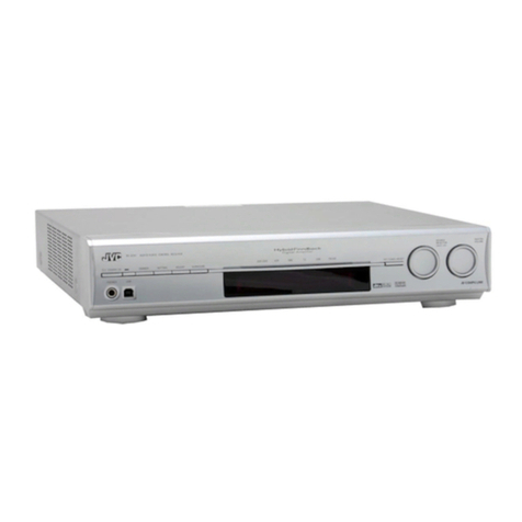
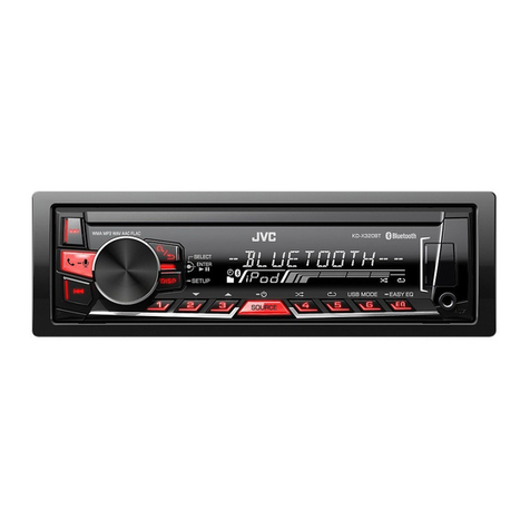
JVC KD-LX300 User manual

SERVICE MANUAL
CD RECEIVER
No.49635
Apr. 2001
COPYRIGHT 2001 VICTOR COMPANY OF JAPAN, LTD.
KD-LX300/KD-LX100
KD-LX300/KD-LX100
Area Suffix
J Northern America
OFF
SEL
10
78
911 12
Difference piont
KD-LX300
KD-LX100
LINE IN
O
X
SUBWOOFER OUT
O
X
Contents
Safety preccaution
Preventing static electricity
Disassembly method
Adjustment method
Extension cord connectiong method
Functions of the mechanism
under the service mode
Flow of functional operation
until TOC read
Maintenance of laser pickup
Replacement of laser pickup
Description of major ICs
1-2
1-3
1-4
1-13
1-14
1-16
1-18
1-19
1-19
1-21~37

KD-LX300/KD-LX100
1-21
FAN8037 (IC661) : CD driver
1. Pin layout & Block diagram
2. Pin function
30
29
28
27
26
25
36
35
34
33
32
31
1
2
3
4
5
6
7
8
9
10
11
12
13 14 15 16 17 18 19 20 21 22 23 24
48 47 46 45 44 43 42 41 40 39 38 37
s
w
s
w
s
w
M
S
C
M
S
C
M
S
C
D
D
D
D
D
D
T.S .D
STAND BY
ALL MUTE
POWER SAVE
1
2
3
4
5
6
7
8
9
10
11
12
13
14
15
16
17
18
19
20
21
22
23
24
I
I
O
I
I
O
I
I
O
I
I
I
I
I
I
-
I
I
I
I
I
I
-
O
CH2 op-amp input(+)
CH2 op-amp input(-)
CH2 op-amp output
CH3 op-amp input(+)
Ch3 op-amp input(-)
CH3 op-amp output
CH4 op-amp input(+)
CH4 op-amp input(-)
CH4 op-amp output(+)
CH5 motor speed control
CH5 forward input
CH5 reverse input
CH6 motor speed control
CH6 forward input
CH6 reverse input
Signal ground
CH7 forward input
CH7 reverse input
CH7 motor speed control
Stand by
Power save
All mute
Power supply voltage
CH7 drive output(-)
IN2+
IN2-
OUT2
IN3+
IN3-
OUT3
IN4+
IN4-
OUT4
CTL1
FWD1
REV1
CTL2
FWD2
REV2
SGND
FWD3
REV3
CTL3
SB
PS
MUTE
PVCC2
DO7-
Pin
No.
Symbol I/O Function
25
26
27
28
29
30
31
32
33
34
35
36
37
38
39
40
41
42
43
44
45
46
47
48
O
O
O
-
O
O
O
O
O
O
-
O
O
O
O
-
I
O
I
I
-
I
I
O
CH7 drive output(+)
CH6 drive output(-)
CH6 drive output(+)
Power ground2
CH5 drive output(-)
CH5 drive output(+)
CH4 drive output(-)
CH4 drive output(+)
CH3 drive output(-)
CH3 drive output(+)
Power ground1
CH2 drive output(-)
CH2 drive output(+)
CH1 drive output(-)
CH1 drive output(+)
Power supply voltage
Regulator feedback input
Regulator output
Regulator reset input
Bias voltage input
Signal supply voltage
CH1 op-amp input(+)
CH1 op-amp input(-)
CH1 op-amp output
DO7+
DO6-
DO6+
PGND2
DO5-
DO5+
DO4-
DO4+
DO3-
DO3+
PGND1
DO2-
DO2+
DO1-
DO1+
PVCC1
REGOX
REGX
RESX
VREF
SVCC
IN1+
IN1-
OUT1
Pin
No.
Symbol I/O Function
Description of major ICs

KD-LX300/KD-LX100
1-22
1
2
3
4
5
6
7
8
9
10
11
12
13
14
15
16
17
18
19
20
21
22
23
24
25
26
27
28
29
30
31
32
33
34
35
36
37
38
39
40
41
42
SW2
SW3
SW4
REST-SW
LM0
LM1
DIMMER-OUT
LCD-PWR
VDD
X2
X1
VSS
XT2
XT1
RESET
SW1
BUS-INT
PS2
CRUISE
NC
NC
REMOCON
AVDD
AVREF0
VOL1
VOL2
KEY0
KEY1
KEY2
LEVEL
NC
S.METER
AVSS
W-VOL
DOT-CONT
AVREF
BUS-SI
BUS-SO
BUS-SCK
STAGE2
LCD-DA
LCDCL
Detection switch of CD mechanism
Reset signal input from CD mechanism
Loading motor control signal output
Dimmer signal output
LCD driver power supply control output H:ON
Power supply terminal
Connecting the crystal oscillator for system main clock
Power supply terminal
Connecting the crystal oscillator for system sub clock
System reset signal input
Detection switch of CD mechanism
Cut-in input for J-BUS signal
Power save 2, Working together back up by H input, to stop mode
Pulse signal input port for Cruise control
Clock signal input for RDS
RDS data input
Remote control signal input
Power supply terminal
Input for rotation volume detection pulse judgment to relation V1
Input for rotation volume detection pulse judgment to relation V2
Key control signal input 0
Key control signal input 1
Key control signal input 2
Signal input port of level meter
Non connect
S.Meter level input
Connect to GND
Subwoofer volume control analogue output
Dot contrast signal output
Power supply terminal
J-BUS data input
J-BUS data output
J-BUS Clock signal I/O
Initial setting
Data output to LCD driver
Clock output to LCD driver
I
I
I
I
O
O
O
O
-
-
-
-
-
-
I
I
I
I
I
-
-
I
-
-
I
I
I
I
I
I
I
I
-
O
O
-
I
O
I/O
I
O
O
Pin No. Symbol I/O Function
UPD784215AGC-128 (IC701) : UNIT CPU
75 ~ 51
1 ~ 25
76
100
50
26
~
~
1.Terminal Layout
2.Pin Function (1/2)

KD-LX300/KD-LX100
1-23
43
44
45
46
47
48
49
50
51
52
53
54
55
56~60
61,62
63
64
65
66
67
68
69
70
71
72
73
74
75
76
77
78
79
80
81
82
83
84
85
86
87
88
89
90
91
92
93
94
95~98
99
100
LCD-CE1
BUZZER
E2PR-DA-I
E2PR-DA-O
E2PR-CLK
BUS-I/O
TM0
TM1
DM0
DM1
SD/ST
LOCAL
MONO
CA-SW1~5
NC
SEEK/STOP
NC
FM/AM
PLL-CE
PLL-DA
PLL-CK
BAND IN
NC
AMP KILL
VSS
DIMMER-IN
PS1
POWER
CD-ON
MUTE
W-LPF1
W-LPF2
W-MUTE
VDD
VO-DA
VOL-CLK
NC
GVSW
LCDRST
LCD-CE2
DMK
TMK
NC
BUCK
CCE
RST
TEST
BUS0~3
DISC SEL
NC
Chip enable output to LCD driver
BUZZER control signal output
Data input terminal from EEPROM
Data output terminal for EEPROM
Clock signal I/O terminal with EEPROM
J-BUS I/O signal terminal
Tray motor negative signal output terminal
Tray motor positive signal output terminal
Door motor negative signal output terminal
Door motor positive signal output terminal
Station detector, Stereo signal input, H:Find Station L:Stereo
Local ON/OFF select signal output terminal
Monaural ON/OFF selecting output, H:MONO ON
DOOR/TRAY open close detect switch signal input terminal
Non connect
Auto seek/stop selecting output, H:Seek L:Stop
Non connect
Selecting output for FM/AM, L:FM H:AM
CE output for IC control for PLL
Data output for IC control for PLL
Clock output for IC control for PLL
AM detect signal input
Non connect
Non connect
Connect to GND
DIMMER signal input terminal
Power supply terminal
Selecting output for power ON/OFF, H:power ON
Power supply control signal for CD H:CD
MUTE output, L:MUTE ON
Subwoofer cut off frequency output 1
Subwoofer cut off frequency output 2
MUTE output for Subwoofer
Power supply terminal
Data output terminal
Clock signal output terminal
Non connect
AGC/FE/TE amp gain change terminal
LCD reset signal output terminal
Chip enable 2 output terminal for LCD driver
Motor speed control signal output terminal
Tray motor control signal output terminal
Non connect
Micon interface clock output terminal
Command and data sending/receiving chip enable signal output
Reset signal output terminal reset at "L" level
Connect to GND
Micon interface data input/output terminal
Initial setting
Non connect
O
O
I
O
O
I/O
O
O
O
O
I
O
O
I
-
O
-
O
O
O
O
I
-
-
-
I
I
O
O
O
O
O
O
-
O
O
-
O
O
O
O
O
-
O
O
O
-
I/O
I
-
Pin No. Symbol I/O Function
Pin Function (2/2)

KD-LX300/KD-LX100
1-24
D/A
A/D
Servo control
ROM
RAM
Digital equalizer
automatic
adjustment circuit
Data
slicer
Sync signal
protection
EFM VCO
CLV servo
PLL
TMAX
Sub code
decoder
Audio output
circuit Digital output
16 k
RAM
Address
circuit
Correction
circuit
1-bit
DAC
PWM
Clock
generator
LPF
Micro-
controller
interface
DVss3 49
RO 50
DVDD3 51
DVR 52
LO 53
DVss3 54
ZDET 55
Vss5 56
BUS0 57
BUS1 58
BUS2 59
BUS3 60
BUCK 61
/CCE 62
/RST 63
VDD5 64
32 TEZI
31 TEI
30 SBAD
29 FEI
28 RFRP
27 RFZI
26 RFCT
25 AVDD3
24 RFI
23 SLCO
22 AVss3
21 VCOF
20 PVREF
19 LPFO
18 LPFN
17 TMAX
48 XVDD3
47 XO
46 XI
45 XVss3
44 TESIN
43 VDD3
42 Vss3
41 DMO
40 FMO
39 AVDD3
38 SEL
37 TEBC
36 RFGC
35 VREF
34 TRO
33 FOO
BCK 1
LRCK 2
AOUT 3
DOUT 4
IPF 5
VDD3 6
Vss3 7
SBOK 8
CLCK 9
DATA 10
SFSY 11
SBSY 12
/HSO 13
/UHSO 14
PVDD3 15
PDO 16
TC9490FA (IC521) : DSP
1. Pin layout & Block diagram
2. Pin function (1/2)
Pin No.
1
2
3
4
5
6
7
8
9
10
11
12
13
I/O
O
O
O
O
O
-
-
O
O
O
O
O
O
Function
Bit clock output terminal
L/R channel clock output terminal
Audio data output terminal
Digital data output terminal
Correction flag output terminal
Digital 3.3V power supply voltage terminal
Digital GND terminal
Subcode Q data CRCC result output terminal
Subcode P-W data read clock I/O terminal
Subcode P-W data output terminal
Playback frame sync signal output terminal
Subcode block sync signal output terminal
Playback speed mode output terminal
Symbol
BCK
LRCK
AOUT
DOUT
IPF
VDD3
Vss3
SBOK
CLCK
DATA
SFSY
SBSY
/HSO

KD-LX300/KD-LX100
1-25
2. Pin function (2/2)
Pin No.
14
15
16
17
18
19
20
21
22
23
24
25
26
27
28
29
30
31
32
33
34
35
36
37
38
39
40
41
42
43
44
45
46
47
48
49
50
51
52
53
54
55
56
57
58
59
60
61
62
63
64
I/O
O
-
O
O
I
O
-
O
-
O
I
-
I
I
I
I
I
I
I
O
O
-
O
O
O
-
O
O
-
-
I
-
I
O
-
-
O
-
-
O
-
O
-
I/O
I/O
I/O
I/O
I
I
I
-
Function
Playback speed mode output terminal
PLL-only 3.3V power supply voltage terminal
EFM and PLCK phase difference signal output terminal
TMAX detection result output terminal
Inverted input terminal for PLL LPF amp
Outpuit terminal for PLL LPF amp
PLL-only VREF terminal
VCO filter terminal
Analog GND terminal
DAC output terminal for data slice level generation
RF signal input terminal
Analog 3.3V power supply voltage terminal
RFRP signal center level input terminal
RFRP signal zero-cross input terminal
RF ripple signal input terminal
Focus error signal input terminal
Sub-beam adder signal input terminal
Tracking error input terminal
Tracking error signal zero-cross input terminal
Focus equalizer output terminal
Tracking equalizer output terminal
Analog reference power supply vpltage terminal
RF amplitude adjustment control signal output terminal
Tracking balance control signal output terminal
APC circuit ON/OFF signal output terminal
Analog 3.3V power supply voltage terminal
Feed equalizer output terminal
Disc equalizer output terminal
Digital GND terminal
Digital 3.3V power supply voltage terminal
Test input terminaal
System clock oscillator GND terminal
System clock oscillator input terminal
System clock oscillator output terminal
System clock oscillator 3.3V power supply voltage terminal
DA converter GND terminal
R-channel data forward output terminal
DA converter 3.3V power supply terminal
Reference voltage terminal
L-channel data forward output terminal
DA converter GND terminal
1 bit DA converter zero data detection flag output terminal
Microcontroller interface GND terminal
Microcontroller interface data I/O terminal
Microcontroller interface clock input terminal
Microcontroller interface chip enable signal input terminal
Reset signal input terminal
Microcontroller interface 5V power supply terminal
Symbol
/UHSO
PVDD3
PDO
TMAX
LPFN
LPFO
PVREF
VCOF
AVss3
SLCO
RFI
AVDD3
RFCT
RFZI
RFRP
FEI
SBAD
TEI
TEZI
FOO
TRO
VREF
RFGC
TEBC
SEL
AVDD3
FMO
DMO
Vss3
VDD3
TESIN
XVss3
XI
XO
XVDD3
DVss3
RO
DVDD3
DVR
LO
DVss3
ZDET
Vss5
BUS0
BUS1
BUS2
BUS3
BUCK
/CCE
/RST
VDD5
KD-LX300/KD-LX100
1-26
1314
CL- LGND OUTL OUTR RGND CR - CR +
CL+ Vcc INL NFL FIL NFR INR
1112 9 810
2143675
REFL REFR
FILTER
BA3220FV-X (IC301,IC401) : Driver
1. Pin layout & Block diagram
2. Pin function
1
2
3
4
5
6
7
8
9
10
11
12
13
14
CL+
Vcc
INL
NFL
FIL
NFR
INR
CR+
CR-
RGND
OUTR
OUTL
LGND
CL-
Powe supply terminal for amp.
power supply terminal.
input terminal.
Negative feedback terminal.
Filter terminal.
Negative feedback terminal.
Input terminal
Power supply terminal for amp.
Output terminal of internal amp.
Rch GND terminal.
Rch output terminal.
Lch output terminal.
Lch GND terminal.
Output terminal of internal amp.
Pin
No.
Symbol Function
000874360-T (IC702) : System reset
1. Pin layout 2. Block diagram
13
2
1 Vcc
3 Vout
2 GND
OP1

KD-LX300/KD-LX100
1-27
BD3860K (IC911) : E. volume
1.Terminal layout
2.Bockdiagram
3.Pin function
13
12
7
8
10
11
41
42
43
44
1
2
3
4
6 5 9 40 36 35 343328323130 2919 15 14
39 38 37 25 24 26 23 22 21 20 18 17 16
GND FIL VCC SEL1
0 18 dB
0 18 dB
VIN1 LOUD1 HF1 LF1 DET1 TIN1 TNF1 BNF1
OUTF1
OUTR1
SI
SC
OUTR2
OUTF2
BOUT2BNF2TNF2TIN2BBOUT2MIX2VCA2DET2LF2HF2LOUD2VIN2SEL2
D2
C2
B2
A2
D1
C1
B1
A1
BOUT1VCA1 MIX1 BBOUT1
POWER
SUPPLY INPUT
GAIN
INPUT
GAIN
MAIN
VOLUME
0 -40 dB
LOUDNESS
MAIN
VOLUME
0 -40 dB
LOUDNESS
LOW(f=50Hz) 6dB
PROCESS CONTROL +3 to 12dB
(f=10kHz)
LOW(f=50Hz) 6dB
PROCESS CONTROL +3 to 12dB
(f=10kHz)
TREBLE
-14 +14dB
TREBLE
-14 +14dB
BASS
-14 +14dB
BASS
-14 +14dB
FADER
CH1 FRONT
0 -5 dB
FADER
CH2 FRONT
0 -5 dB
FADER
CH1 REAR
0 -5 dB
FADER
CH2 REAR
0 -5 dB
LOGIC
INPUT
SELECTOR
1
2
3
4
5
6
7
8
9
10
11
12
13
14
15
16
17
18
19
20
21
22
CH2 Input Pin A
CH2 Input Pin B
CH2 Input Pin C
CH2 Input Pin D
1/2 VCC Pin
Ground Pin
Serial Data Receiving Pin
Serial Clock Receiving Pin
Power Supply Pin
CH2 Rear Output Pin
CH2 Front Output Pin
CH1 Rear Output Pin
CH1 Front Output Pin
CH1 Bass Filter Setting Pin
CH2 Bass Filter Setting Pin
CH2 treble Filter Setting Pin
CH1 treble Filter Setting Pin
CH2 treble Input Pin
CH2 BBE II Signal Output Pin
CH2 Output MIX Amplifier
Inverse Input Pin
A2
B2
C2
D2
FIL
GND
SI
SC
VCC
OUTR2
OUTF2
OUTR1
OUTF1
BOUT1
BNF1
BOUT2
BNF2
TNF2
TNF1
TIN2
BBOUT2
MIX2
Pin
No. Symbol Function
23
24
25
26
27
28
29
30
31
32
33
34
35
36
37
38
39
40
41
42
43
44
CH2 High Pass VCA Output Pin
CH2 Low Pass Filter Setting Pin
CH2 High Pass Filter Setting Pin
CH2 High Pass Attack/Release Time Setting Pin
Non connect
CH1 High Pass Attack/Release Time Setting Pin
CH1 treble Input Pin
CH1 BBE II Signal Output Pin
CH1 Output MIX Amplifier Inverse Input Pin
CH1 High Pass VCA Output Pin
CH1 Low Pass Filter Setting Pin
CH1 High Pass Filter Setting Pin
CH1 Loudness Filter Setting Pin
CH1 Main Volume Input Pin
VCH2 Loudness Filter setting Pin
CH2 Main Volume Input Pin
CH2 Input Gain Output Pin
CH1 Input Gain output Pin
CH1 Input Pin A
CH1 Input Pin B
CH1 Input Pin C
CH1 Input Pin D
VCA2
LF2
HF2
DET2
NC
DET1
TIN1
BBOUT1
MIX1
VCA1
LF1
HF1
LOUD1
VIN1
LOUD2
VIN2
SEL2
SEL1
A1
B1
C1
D1
Pin
No. Symbol Function
1 11
33 23
34
44
22
12

KD-LX300/KD-LX100
1-28
VCC WP SCL SDA
A0 A1 A2 GND
8 Vcc
7 WP
6 SCL
5 SDA
A0 1
A1 2
A2 3
GND 4
16kbit EEPROM allay
11bit
11bit
8bit
Address
decoder
Slave Ward
Address resister
Data
resister
START STOP
ACK
Control circuit
High voltage osc circuit Power supply
voltage det.
VCC
GND
A0,A1,A2
SCL
SDA
WP
-
-
I
I
I/O
I
Power supply.
GND
No use connect to GND.
Serial clock input.
Serial data I/O of slave and ward address.
Write protect terminal.
Symbol I/O Function
BR24C16F-X (IC703) : EEPROM
1. Pin layout
3. Block diagram
2. Pin function
14 13 12 11 810 9
1234 756
VDD C1 C4 I/O4 I/O3O/I4 O/I3
I/O1 O/I1 O/I2 I/O2 VssC2 C3
BU4066BCFV-X (IC322) : Quad analog switch
1. Pin layout & Block diagram

KD-LX300/KD-LX100
1-29
2
1
11
12
10
15 13
14
5
4
6
3
8
9
7
ILM AJGND
C6
10u
C5
0.1u
C4
0.1u
C3
0.1u
AUDIO OUT
CD OUT
CTRL
ANT CTRL
EXT OUT
ANT OUT
VCC ACC
Surge Protector
BIAS TSD
C1
100u C2
0.1u
+B
ACC
BATT.DET OUT
COMPOUT
VDD OUT
SW5VOUT
ILMOUT
C7
0.1u
C8
0.1u
R1
UNIT R:
C:F
note1) TAB (header of IC)
connected to GND
HA13164 (IC961) : Regulator
1.Terminal layout
2.Block diagram
3.Pin function
Pin No. Symbol Function
1
2
3
4
5
6
7
8
9
10
11
12
13
14
15
EXTOUT
ANTOUT
ACCIN
VDDOUT
SW5VOUT
COMPOUT
ANT CTRL
VCC
BATT DET
AUDIO OUT
CTRL
CD OUT
ILM AJ
ILM OUT
GND
Output voltage is VCC-1 V when M or H level applied to CTRL pin.
Output voltage is VCC-1 V when M or H level to CTRL pin and H level
to ANT-CTRL.
Connected to ACC.
Regular 5.7V.
Output voltage is 5V when M or H level applies to CTRL pin.
Output for ACC detector.
L:ANT output OFF , H:ANT output ON
Connected to VCC.
Low battery detect.
Output voltage is 9V when M or H level applied to CTRL pin.
L:BIAS OFF, M:BIAS ON, H:CD ON
Output voltage is 8V when H level applied to CTRL pin.
Adjustment pin for ILM output voltage.
Output voltage is 10V when M or H level applies to CTRL pin.
Connected to GND.
123456789101112131415

KD-LX300/KD-LX100
1-30
1
2
3
4
5
6
7
14
13
12
11
10
9
8
OE1
A1
Y1
OE2
A2
Y2
Vss
Vcc
OE4
A4
Y4
OE3
A3
Y3
HD74HC126
HD74HC126FP (IC771) : Changer control
M5282FP-XE (IC321) : E. volume
1. Pin layout
3. Pin function
2. Block diagram
1
2
3
4
5
10
9
8
7
6
1
2
3
10
457 8
9
1
2
3
4
5
6
7
8
9
10
Vcc/2 output for microphone amp.
Microphone amp. positive input terminal.
Microphone amp. negative input terminal.
Microphone amp. output terminal.
Ground.
Non connection.
VCA input terminal.
VCA control terminal.
VCA output terminal.
Power supply.
Vcc/2
Amp+IN
Amp-IN
Amp OUT
GND
NC
VCA IN
Vc
VCA OUT
Vcc
Pin
No.
Symbol Function
+–
6
7
5
8
B
+–
2
1
3
4
A
A OUT
A IN–
A IN+
VEE
VCC
B OUT
B IN–
B IN+
NJM2100M (IC821) : Operation amp

KD-LX300/KD-LX100
1-31
11
620
1
4
10
15
25
13
14
16
12
9
8
5
7
2
22
17
19
18
21
23
24
3
-
+
-
+
-
+
-
+
-
+
-
+
-
+
-
+
IN 1
IN 2
ST BY
Vcc 1/2 Vcc 3/4
OUT 1+
OUT 1-
PWR GND1
OUT 2+
OUT 2-
PWR GND2
R.F
IN 3
IN 4
PRE GND
ON TIME C
Muting &
ON Time Control
Circuit
Protective
circuit
Protective
circuit
Mute
circuit
Ripple
Filter
Stand by
Switch
N.C
TAB
Mute
OUT 3+
OUT 3-
PWR GND3
OUT 4+
OUT 4-
PWR GND4
LA4743K (IC941) : Power amp
1.Block diagram
2.Terminal layout
3.Pin function
TAB
GND
OUTRR-
STBY
OUTRR+
VCC1/2
OUTRF-
GND
OUTRF+
RIPPLE
INRF
INRR
SGND
INLR
INLF
ONTIME
OUTLF+
GND
OUTLF-
VCC3/4
OUTLR+
MUTE
OUTLR-
GND
NC
1
2
3
4
5
6
7
8
9
10
11
12
13
14
15
16
17
18
19
20
21
22
23
24
25
SymbolPin No. Function
Header of IC
Power GND
Outpur(-) for front Rch
Stand by input
Output (+) for front Rch
Power input
Output (-) for rear Rch
Power GND
Output (+) for rear Rch
Ripple filter
Rear Rch input
Front Rch input
Signal GND
Front Lch input
Rear Lch input
Power on time control
Output (+) for rear Lch
Power GND
Output (-) for rear Lch
Power input
Output (+) for front
Muting control input
Output (-) for front
Power GND
Non connection

KD-LX300/KD-LX100
1-32
COMMON
DRIVER
INSTRUCTION
DECODER
INSTRUCTION
REGISTER
ADRAM
60
bits
SEGMENT DRIVER
LATCH
CGRAM
5x9x16
bits
DCRAM
48x8
bits
CGROM
5x9x240
bits
ADDRESS
COUNTER
ADDRESS
REGISTER
TIMING
GENERATOR
CLOCK
GENERATOR
SHIFT REGISTER
CCB INTERFACE
S60/COM9
S59/COM10
S58
S1
DI
CL
CE
OSCI
OSCO
RES
VDD
VLCD
VLCD1
VLCD2
VLCD3
VSS
COM1
COM8
1 ~ 20
60 ~ 41
61
80
40
21
~
~
LC75811W (IC602) : LCD driver
1. Pin layout
2. Block diagram
3. Pin function
1~58
59
60~65
66
67
68
69~71
72
73
74
75
76
77
78
79~80
O
O
O
O
-
-
I
-
O
I
I
I
I
I
O
Segment driver output terminal
Common driver output terminal
Power supply for logic section
Power supply for LCD driver section
LCD voltage input terminal
Connect to ground
Oscillation output terminal
Oscillation input terminal
Reset signal input terminal
Chip enable input terminal
Clock signal input terminal
Serial data input terminal
Segmrnt driver output terminal
S3~S60
COM0
COM3~COM8
COM1
VDD
VLCD
VLCD1~VLCD3
VSS
OSCO
OSCI
RES
CE
CL
DI
S1~S2
Pin No.
Symbol I/O Function

KD-LX300/KD-LX100
1-33
1
2
3
4
5
6
7
8
9
10
11
12
13
14
15
16
S1
S2
S3
S4
S5
S6
S7
S8
S9
S10
S11
S12
S13
S14
S15
S16 17 18 19 20 21 22 23 24 25 26 27 28 29 30 31 32
48
47
46
45
44
43
42
41
40
39
38
37
36
35
34
33
S48
S47
S46
S45
S44
S43
S42
S41
S40
S39
S38
S37
S36
S35
S34
S33
64 63 62 61 60 59 58 57 56 55 54 53 52 51 50 49
S17
S18
S19
S20
S21
S22
S23
S24
S25
S26
S27
S28
S29
S30
S31
S32
DI
CL
CE
OSC
Vss
VDD2
VDD1
INH
VDD
COM3
COM2
COM1
S52
S51
S50
S49
LC75823W (IC602) : LCD driver
1. Pin Layout & Symbol
2. Pin Function
Pin No.
1 to 52
53 to 55
56
57
58
59
60
61
62
63
64
I/O
O
O
--
I
I
I
--
I/O
I
Segment output pins used to display data transferred
by serial data input.
Common driver output pins. The frame frequency is given
by : t0=(fosc/384)Hz.
Power supply connection. Provide a voltage of between
4.5 and 6.0V.
Display turning off input pin.
INT="L" (Vss) ----- off (S1 to S52, COM1 to COM3="L"
INT="H" (VDD)----- on
Serial data can be transferred in display off mode.
Used for applying the LCD drive 2/3 bias voltage
externally.
Must be connected to VDD2 when a 1/2 bias drive scheme
is used.
Used for applying the LCD drive 1/3 bias voltage
externally.
Must be connected to VDD1 when a 1/2 bias drive scheme
is used.
Power supply connection. Connect to GND.
Oscillator connection.
An oscillator circuit is formed by connecting an external
resistor and capacitor at this pin.
Serial data CE : Chip enable
interface connection
to the controller. CL : Sync clock
DI : Transfer data
Symbol
S1 to S52
COM1 to COM3
VDD
INH
VDD1
VDD2
Vss
OSC
CE
CL
DI
Function

KD-LX300/KD-LX100
1-34
A OUT 1
A -IN 2
A +IN 3
GND 4
8 V+
7 B OUT
6 B -IN
5 B +IN
NJM2904M (IC951) : Dual ope amp
1. Pin layout
1. Pin layout & Block diagram
A OUTPUT 1
A - INPUT 2
A + INPUT 3
V- 4
8 V+
7 B OUTPUT
6 B - INPUT
5 B + INPUT
BA
NJM4565MD (IC323,IC960) : Ope amp
RPM6938-SV4 (IC603) : Remote censor
Vcc
Vcc
Comp
AGC
AMP
PD
Detector
BPF
fo
trimming
circuit
I/V
conversion
magnetic shield
Rout
GND
22k
1.Block diagram

KD-LX300/KD-LX100
1-35
20 k 20 k
20 k
2 k
2 k
1 k
20 k
20 k
40 k
40 k
20 k
20 k
20 k
20 k
60 k
60 k
3 k
3 k
20 k
40 k
30 k
15 k
15 k
50 k
50 k
14 k
80 k
80 k
1.75 k
240 k
180 k
180 k
240 k
12 k
12 k
10 pF
10 pF
50 A
20 A
60 A
BOTTOM
PEAK
PEAK
1.3V
15 pF
40 pF
40 pF
15 pF
k
1
x0.5
x2
x0.5
x2
GVSW 13
VRO 14
FEO 15
FEN 16
RFRP 17
RFRPIN 18
RFGO 19
RFGC 20
AGCIN 21
RFO 22
RFN 23
GND 24
12 RFDC
11 TEO
10 TEN
9 REBC
8 SEL
7 LDO
6 MDI
5 TNI
4 TPI
3 FPI
2 FNI
1 Vcc
TA2147F-X (IC601) : Head amp
1. Pin layout & Block diagram
2. Pin function
Pin No.
1
2
3
4
5
6
7
8
9
10
11
12
13
14
15
16
17
18
19
20
21
22
23
24
I/O
-
I
I
I
I
I
O
I
I
I
O
O
I
O
O
I
O
I
O
I
I
O
I
-
Symbol
Vcc
FIN
FPI
TPI
TNI
MDI
LDO
SEL
TEBC
TEN
TEO
RFDC
GVSW
VRO
FEO
FEN
RFRP
RFRPIN
RFGO
RFGC
AGCIN
RFO
RFN
GND
Function
3.3V power supply terminal
Main-beam amp input terminal
Sub-beam amp input terminal
Monitor photo diode amp input terminal
Laser diode amp output terminal
APC circuit ON/OFF control signmal, laser diode (LDO) control signal input or
bottom/peak detection frequency change terminal
Tracking error balance adjustment signal input terminal
Tracking error signal generation amp negative-phase input terminal
Tracking error signal generation amp output terminal
RF signal peak detection output terminal
AGC/FE/TE amp gain change terminal
Reference voltage (VRO) output terminal
Focus error signal generation amp output terminal
Focus error signal generation amp negative-phase input terminal
Signal amp output pin for track count
Signal generation amp input terminal for track count
RF signal amplitude adjustment amp output terminal
RF amplitude adjustment control signal input terminal
RF signal amplitude adjustment amp input terminal
RF signal generation amp output terminal
RF signal generation amp input terminal
GND terminal

KD-LX300/KD-LX100
1-36
125
TAB
IN1
IN2
IN3
IN4
OUT4 (-)
OUT3 (-)
OUT2 (-)
OUT1 (-)
OUT1 (+)
OUT4 (+)
OUT3 (+)
OUT2 (+)
PW-GND4
PW-GND3
PW-GND2
PW-GND1
RIP STBY MUTE
DIAGNOSIS
OUT
AUX IN
Vcc1 Vcc2
120 6
11
9
8
7
5
2
3
12
16
17
18
19
15
14
21
24
23
13
10 425 22
TA8273H (IC941) : 4ch amp
1. Pin layout 2. Block diagram

KD-LX300/KD-LX100
1-37
1
24
2
15
16
13
3
4
5
6
78910 11 12 14 17 21 23
18
19
22
20
Buff.
ON/OFF
OSC circuit
AMP
AMP
AMP
Reference Counter
Phase
Comparator
Prescaler 4-bit
Swallow counter
12-bit
Programmable counter
Constant
power supply voltage
AM CP.
switch
switch
REG.
vt
FM cp
+
-
+
-
a-gnd
vccd-gndvdd
vdd2
out-2out-1
I/O -2I/O -1
SL
osc
XO
XI
FM VCO
AMVCO
IFC
CE
DIN
DOUT
DIMM
20-bit BINARY COUNTER
Serial
Interface
Resistor 1
Resistor 2 22-bit
40bit shift register
I/O PORT OUTPUT PORT Vdd Vcc
TB2118F-X (IC21) : PLL
1.Terminal Layout
2.Block diagram
Pin
No. Symbol I/O Function
1
2
3
4
5
6
7
8
9
10
11
12
XOUT
OSC
CE
DI
CK
DOUT
SR
I/01
I/02
OUT1
OUT2
VDD2
Crystal oscillator pin
Non connect
Chip enable input
Serial data input
Clock input
Serial data output
Register control pin
I/O ports
I/O ports
Non connect
Non connect
Single power supply for REF. frequency block
O
-
I
I
I
O
O
I/O
I/O
-
-
-
Pin
No.
Symbol I/O Function
13
14
15
16
17
18
19
20
21
22
23
24
IFC
VDD
FMIN
AMIN
DGND
FMCP
VT
AMCP
VCC
RF
AGND
XIN
IF signal input
Power pins for digital block
FM band local signal input
AM band local signal input
Connect to GND (for digital circuit)
Charge pump output for FM
Tuning voltage biased to 2.5V.
Charge pump output for AM
Power pins for analog block
Ripple filter connecting pin
Connect to GND (for analog circuit)
Crystal oscillator pin
I
-
I
I
-
O
-
O
-
I
-
I
3.Pin Function
1
2
3
4
5
6
7
8
9
10
11
12
24
23
22
21
20
19
18
17
16
15
14
13

ABCD E F G
1
2
3
4
5
2-1
KD-LX300/KD-LX100
Block diagram
CN601
KEY
MARTIX
LED
MATRIX
LCD
IC601
LCD DRIVER
IC602
LCD DRIVER
COM1~COM3
S1~S52
COM1~COM3
S1~S52
IC603
REMOCON
REMOCON
RESET
KEY2
LCDDA
LCDCL
LCDCE1
LCDCE2
LCDRST
LCDDA
LCDCL
LCDCE1
LCDCE2
LCDRST
CASW4
CASW5
AUX IN
SUB WOOFER
CN302
LINE OUT
CN301
SPK
BATT
CN901
CN601
CN702 CN701
IC941
POWER AMP
IC301
DRIVER
IC401
DRIVER
IC323
OP AMP
IC321
E.VOL
IC322
SWITCH
IC821
CRUISE
IC911
E.VOL
IC171
LINE IN
TU1
FM/AM
TUNER PACK
IC21
PLL
IC701
CPU
IC771
JVC BUS
IC661
CD & TRAY
/DOORLOADING
DRIVER
CD
MECHA
IC702
RESET
IC521
DSP & DAC
IC601
RF AMP
IC960
CD LPF
IC703
EEPROM
J1
ANT
CN771
CD CHANGER
CN631
KEY
MARTIX
KEY0
KEY1
KEY0
KEY1
VOL1
VOL2
KEY2
DOT
REMOCON
RESET
BUS-SCK
BUS-SO
BUS-SI
BUS-INT
E2PR-CLK
E2PR-DA-I
E2PR-DA-O
RESET
CRUISE
TNI,TPI,FPI
FNI,MDI,LDI
FEO,RFRP,RFBO
RFBC,SEL,TEB
TEN,TEO,RFDC
CD-L
CD-R
LO
RO
LO ,TRAY
FO ,FE
SP ,TR
BUS0~BUS3
BUCK,CCE
RESET
TMK,TM1,TM0
DMK,DM0,DM1
LM0,LM1
CD-ON,REST
TU-L
TU-R
LOUTF
LOUTR
ROUTF
ROUTR
SUBW-L
SUBW-R
W.MUTE
W-LPF1
W-LPF2
W.VOL
FIL
FIR
SEEK/STOP
FM/AM
FM/AMOSC
BANDIN
PLL-CK
PLL-DA
PLL-CE
FM/AM
CH-L
CH-R
AU.IL
AU.IR
FRONTL
FRONTR
REARL
REARR
OUTFL
OUTFR
OUTRL
OUTRR

Parts are safety assurance parts.
When replacing those parts make
sure to use the specified one.
TUNER SIGNAL
CD SIGNAL
CD CHANGER SIGNAL
AUX IN SIGNAL
SUB WOOFER SIGNAL
FRONT SIGNAL
REAR SIGNAL
HABC DE FG
1
2
3
4
5
KD-LX300/KD-LX100KD-LX300/KD-LX100
2-2
Standard schematic diagrams
Main amp sction
Other manuals for KD-LX300
2
This manual suits for next models
1
Table of contents
Other JVC Receiver manuals

JVC
JVC LVT0178-001A User manual

JVC
JVC RX-6000VBK User manual

JVC
JVC RX-7032VSL User manual

JVC
JVC RX-7001PGD User manual

JVC
JVC LVT0142-006A User manual

JVC
JVC RX5032VSL - Dolby/DTS 5 x Receiver User manual

JVC
JVC KD-X282BT User manual

JVC
JVC RX-8040B User manual

JVC
JVC RX-7010RBK User manual

JVC
JVC rx-701vbk User manual

JVC
JVC KD-X220 User manual

JVC
JVC UX-G357UT User manual

JVC
JVC RX5032VSL - Dolby/DTS 5 x Receiver User manual

JVC
JVC KD-G615 Guide

JVC
JVC KD-ADV5490J User manual

JVC
JVC RX-668RBKJ User manual

JVC
JVC RX-DP10VBK - AV Receiver User manual

JVC
JVC EXAD KW-AVX708 User manual

JVC
JVC KD-LH911 Building instructions

JVC
JVC KD-X362BT User manual