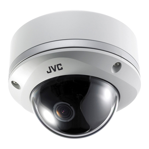
JVC TK-C655 User manual

18
Setting Up the Camera Using an RM-P2580
Setup Procedure
In systems using an RM-P2580 remote control unit, the menus for use during camera setup can be displayed on the remote control
unit. (Please refer to the instructions for RM-P2580.)
<Setting the camera menus from an RM-P2580>
1.
Set the Power switch on the rear panel of the RM-
P2580 to ON.
The POWER lamp lights up.
2.
Press and hold the MENU button for 3 seconds.
•The LED of the MENU button lights up.
•The SETUP menu of the remote control unit is displayed on the
monitor connected to MONITOR OUTPUT-1.
3.
Move the PAN/TILT lever downwards to move the
cursor (>) to “CAMERA” in the menu.
•Tilting the lever upwards (䊱) moves the cursor upwards.
•Tilting the lever downwards (䊲) moves the cursor downwards.
4.
Press the SET button.
•The MENU screen for the camera is displayed.
•Items followed by “..” have further submenus.
5.
Tilt the PAN/TILT lever up or down to select an item.
6.
Tilt the PAN/TILT lever to the left or right to change
the value of the item.
•Tilting the lever towards the left (䊴) decreases the value.
•Tilting the lever towards the right ( 䊳) increases the value.
7.
Press the MENU button.
After completing the setup of the menu items, press the MENU but-
ton to return to the previous menu screen.
SETUP
MENU SET
SPEED
IRIS
AF
FOCUS
ZOOM
OPEN
FAR
TELE CLEAR
/HOME
7
4
1
8
0
5
2
9
6
3
ENTER
AUTO
PAN
OPTION
1
OPTION
2
CAMERA
POSI-
TION
AUTO
PATROL
CLOSE
NEAR
WIDE
AUTO F-1 F-2 F-3
PAN/TILTLENS
CAMERA/POSITION
CAMERA POSITION
REMOTE CONTROL UNIT
RM-P2580
ALARM
POWER
KEY LOCK
PAN/TILT
lever
Power switch
(Rear panel)
POWER lamp
SET button
MENU button
POS ITION SETUP. .
SETUP
CAMERA . .
CONTROL UN I T . .
cursor
SETUP menu of the remote control unit
CAM . FUNCT I ON . .
–––MEN U – – –
CAM . T I T LE / AL ARM . .
CAM . V I DEOADJUST . .
CAM . A LC / E xDR . .
AUTO PAN / PATROL / TRACE . .
POS I . FUNCT I ON SET . .
FACTORY SETT I NGS . .
SETUP menu of the camera
Indication of
presence of
submenus
Example of a submenu
Added
POS .TITLE LOC. UP-L
–––CAMERA FUNCT I ON– – –
FL IP DIGITAL
VAR .P/T SPEED ON
EASY AF OFF
D.ZOOM MAX X2
V . S H A R P N E S S N O R M A L
TILT LIMIT 5 °
V . P H A S E 0
Change mark
..KSAMETAVIRP
Downloaded from: https://www.usersmanualguide.com/

19
Menu Screen Flow
The menu screens are arranged in a hierarchical structure as shown below. Refer to the respective reference pages for the details of each
menu.
POS I T I ON SETUP . .
SETUP
CAMERA . .
CONTROL UN I T . .
CAM . FUNCT I ON . .
–––M E N U – – –
CAM . T I T LE / ALARM. .
CAM . V I DEO ADJ UST . .
CAM . ALC / E x DR . .
AUTO PAN / PATROL / TRACE . .
POS I . FUNCT I ON SET . .
FACTORY SETT I NGS . .
COL OUR L EV E L NORMA L
–––CAMERA VIDEO ADJUST–––
ENHANCE LEVEL NORMAL
PEDESTAL LEVEL NORMAL
AUTO BLK . CT L . OFF
CAM . T I T LE ED I T . .
–––CAMERA T I T LE / A LARM
–––
AREA T I T LE OFF
AREA T I T LE ED I T . .
ALM. T I TLE S IZE DOUB L E
ALM. T I TLE COLOUR WH I TE
ALARM T I TLE ED I T . .
AVERAGE : PEAK 8 : 2
–––CAMERA ALC / E xDR
–––
SHUTTER 1 / 5 0
AGC MODE 1 0 dB
SENSE UP OFF
ExDR MODE OF F
ExDR LEVEL –––
AUTO PAN MODE RETURN
––AUTO PAN / PATROL / TRACE
––
AUTO PAN SPEED NORMAL
A.PAN START POS.SET. .
A.PAN RETURN POS.SET. .
AUTO PATROL SET . .
AUTO TRACE SET . .
RM . A .PAN KEY A.PAN
RM . A .PATROL KEY A.PATROL
CANCEL
––FACTORY SETTINGS– –
CLEAR(W/ O POS I . TITLE)
CLEAR ( ALL )
POS I T I ON T I T L E . .
––POSI T ION FUNCTION SET – –
IRIS MODE AUTO
BLC OFF
W. BALANCE ATW
R-B GAIN –––
M-G GA IN – ––
Normal screen
SETUP screen of the remote control unit
☞
P.20
CAMERA FUNCTION screen
CAMERA VIDEO ADJUSTMENT screen
AUTO PAN/PATROL/TRACE screen
POSITION FUNCTION SET screen
☞
P.22
☞
P.24
☞
P.25
☞
P.21
CAMERA TITLE/ALARM screen
CAMERA ALC/ExDR screen
☞
P.22
☞
P.24
FACTORY SETTINGS screen
POS .TITLE LOC. UP-L
–––CAMERA FUNCT I ON– – –
FL IP DIGITAL
VAR .P/T SPEED ON
EASY AF OFF
D.ZOOM MAX X2
V . SHARPNESS NORMAL
TILT LIMIT 5 °
V . P H A S E 0
..KSAMETAVIRP
Added
MENU screen
•Menus for setting up the function of
each camera:
CAM. FUNCTION
CAM. TITLE/ALARM
CAM. VIDEO ADJUST
CAM. ALC/ExDR
AUTO PAN/PATROL/TRACE
•Menu for setting up the function of
each preset position:
POSI. FUNCTION SET
c
Downloaded from: https://www.usersmanualguide.com/

20
Added
Function & Setting
This adjusts the vertical synchronization to those of other cameras when a selector
switch for the synchronizing system on the Ceilling Mount is at LL. (50 Hz power
region only.)
Setting values : –156 to 0 to 156
Sets the location of the position title and area title in the monitor.
UP : At the top of the screen.
DOWN : At the bottom of the screen.
L: In the left half of the screen.
C: In the centre of the screen.
R: In the right half of the screen
Setting values : UP-L, UP-C, UP-R, DOWN-L, DOWN-C, DOWN-R
When a tilting operation is started while this item is OFF, the camera will stop at the
position where it is pointing straight downwards. When an object moves directly
below the camera, the camera makes three movements 1points the straight down-
wards 2pans 180° 3points upwards.
The FLIP function makes it possible to reduce these operations. Use this function
when monitoring an object passing directly below the camera.
OFF : Tu r ns the FLIP function off.
DIGITAL : Once the camera reaches a tilt of 135˚ from horizontal after passing a
position facing directly downwards, a picture is inverted both vertically
and horizontally.
AUTO : When the camera reaches a position facing directly downwards, it pans
by 180° then stops.
Under this function, the panning and tilting speeds are adjusted automatically rela-
tive to the zoom ratio of the lens. Setting the zoom lens towards TELE decreases
the pan and tilting speeds.
Setting the zoom lens towards WIDE end increases the pan and tilting speeds.
Use this function when monitoring objects at differing zoom ratios.
OFF : Tu r ns this function off.
ON : Tu r ns this function on.
When this item is set to ON, the auto focusing (AF) is activated automatically dur-
ing manual pan/tilt and zoom operations.
This function is convenient when frequent manual operations are expected as it
eliminates the need to focus manually after every manual operation.
OFF : Turns this function off.
ON : Tu r ns this function on.
When the zoom lens is set toward TELE, optical zooming is activated first and
electronic zooming second. This function sets the maximum zoom ratio of the
electronic zooming.
Setting values : x1, x2, x4, x6, x8, x10.
This function sets sharpness in the vertical direction of the image.
NORMAL : Normal sharpness.
HIGH : High sharpness.
Setting Up the Camera Using an RM-P2580
CAMERA FUNCTION Screen
This screen sets up the functions of the camera itself.
Item
V. PHASE
POS.TITLE LOC.
FLIP
VAR. P/T SPEED
EASY AF
D. ZOOM MAX
V.SHARPNESS
Auto focusing may sometimes be incapable of bringing certain objects into accurate focus.
(☞P. 5 )
In this case, use the manual focusing facility.
MEMO
The following phenomena may be observed when HIGH is selected. This is not a malfunc-
tion.
• Horizontal stripes are observed on bright objects.
• Vague horizontal stripes are observed under low light conditions.
CAUTION
●Note Picture quality deteriorates under electronic zooming as it is accompanied by digital
image processing.
●An increase in the electronic zooming ratio may deviate the center of the image slightly
toward the top left. This is due to the camera properties and is not a malfunction.
●Continuous operation from optical zooming to electronic zooming is not available. When
optical zooming reaches the TELE end, press the TELE button again.
MEMO
Initial Value
0
UP-L
DIGITAL
ON
OFF
x2
NORMAL
Downloaded from: https://www.usersmanualguide.com/

21
Function & Setting
OFF :Tilt angle not limited. Horizontal shooting is also possible.
1°-10° :The camera may be operated manually to be tilted between the vertical
position and preset limit at any position between 1° and 10° from the hori-
zontal ceiling.
This function grays out sections that are not to be displayed in the monitored pic-
ture area.
The grayed out section moves accordingly when the camera is panned, tilted or
when the zoom is adjusted.
☞P.26, “PRIVATE MASK Setup”
Initial Value
–
OFF
–
DOUBLE
WHITE
–
Function & Setting
This sets the title which is displayed permanently at the bottom left of the picture.
This title can be up to 16 characters in length.
☞P. 27, “CAMERA TITLE Setup”
The 360° panning range can be divided into 16 areas and a title, of up to 16-
character in length, can be set for each area. As the camera is panned manually
these area titles are displayed. This function determines whether area titles are
displayed or not.
ON : Display area titles.
OFF : Do not display area titles.
Sets the area titles.
☞P. 28, “AREA TITLE Setup”
Sets the size of the characters in the alarm title. (Displayed when an alarm is acti-
vated.)
NORMAL :Same size as the characters used in the menu screen.
DOUBLE :Double the size, both horizontally and vertically, of the characters used
in the menu screen.
Sets the colour of the alarm titles.
Setting values: WHITE, YELLOW, CYAN, GREEN
Sets the alarm titles.
☞P. 29, “ALARM TITLE Setup”
CAMERA TITLE/ALARM Screen
This screen sets items related to titles and alarms.
*This unit is not equipped with alarm input/output.
The item ALARM TITLE is used to set the alarm title, which is displayed when an alarm signal is input to the RM-P2580 remote
control unit. (Please refer to the instruction manual for the RM-P2580.)
Item
CAM. TITLE EDIT ..
AREA TITLE
AREA TITLE EDIT ..
ALM.TITLE SIZE
ALM. TITLE COLOUR
ALARM TITLE EDIT ..
Item
TILT LIMIT
PRIVATE MASK..
Initial Value
5°
–
●Since the dome cover is of a hemispherical shape, the picture tends to become distorted
at the edges of the hemisphere. When the camera is tilted and pointed in the horizontal
direction, the picture may be out of focus because the camera captures the edges of the
hemisphere. If this phenomenon causes concern, set the “TILT LIMIT” in order to avoid it.
●The tilting range, which is set as the TILT LIMIT can be recalled if it has been set as a
function of the preset registration or as the Auto Trace setting operation.
MEMO
Added
Downloaded from: https://www.usersmanualguide.com/

Setting Up the Camera Using an RM-P2580
PRIVATE MASK Setup
Use the PRIVATE MASK screen to set up the private mask function, which grays out areas that are not required to be included in
the monitored picture. Up to four private masks can be set per screen, and up to eight private masks can be set in total.
SETUP
MENU SET
SPEED
IRIS
AF
FOCUS
ZOOM
OPEN
FAR
TELE CLEAR
/HOME
7
4
1
8
0
5
2
9
6
3
ENTER
AUTO
PAN
OPTION
1
OPTION
2
CAMERA
POSI-
TION
AUTO
PATROL
CLOSE
NEAR
WIDE
AUTO F-1 F-2 F-3
PAN/TILTLENS
CAMERA/POSITION
CAMERA POSITION
REMOTE CONTROL UNIT
RM-P2580
ALARM
POWER
KEY LOCK
PAN/TILT
lever
CAMERA
buttons
TELE
button
WIDE button
ENTER
button
Numeric keys
SET button
MENU button
POS . T I T L E LOC . UP - L
–––CAMERA FUNCT I ON– – –
FL IP DIGITAL
VAR . P / T SPEED ON
EASY AF OFF
D.ZOOM MAX X2
V . S H A R P N E S S N O R M A L
TILT LIMIT 5 °
V . P H A S E 0
..KSAMETAVIRP
Added
MODE ON
–––PRIVATE MASK–––
MASK NO 1
*
MASK ED IT. .
MASK DELETE . .
Already set.
–––MASK EDIT–––
PUSH MENU SAVE&RETURN
→
CANCEL
–––MASK DELETE–––
DELETE
1.
Select the camera. (
☞
RM-P2580 Instruction manual)
CAMERA button →Numeric key (camera number) →ENTER button.
The picture of the selected camera is output.
2.
Select the angle of view.
Use the PAN/TILT lever and the lens button to set the viewing angle
to which the private mask function is to be applied.
3.
Display the SETUP menu on the camera.
(☞P. 18, steps
1
to
4
)
MENU button (3 sec.)
→
Select “CAMERA” using the PAN/TILT
lever
→
SET button.
The camera moves to the home position.
4.
Tilt the PAN/TILT lever up or down to move the cursor
(>) to “CAMERA FUNCTION” and press the SET button.
The CAMERA FUNCTION menu is displayed.
5.
Move the cursor (>) to “PRIVATE MASK” and press
the SET button.
The PRIVATE MASK submenu is displayed.
6.
Select the private mask function ON or OFF.
Turn the private mask function on or off by setting the “MODE” item
in the submenu to ON or OFF (Factory setting: OFF)
7.
Select the mask number.
Select the private mask number from MASK NO. 1 to 8 and move the
cursor on to the item “MASK EDIT.” Of these, a maximum of 4 can be set
within one picture.
If an already set mask number is selected, the (
*
) mark will be displayed.
8.
Edit the masking area.
•Move the cursor to “MASK EDIT” and press the SET button to
display the MASK EDIT screen. (The masked area will be dis-
played as a grayed-out area.)
•Tilt the PAN/TILT lever to move the grayed-out area to the centre
of the area to be masked.
•Press the TELE and WIDE buttons to set the masked area size.
9.
Press the MENU button.
• The screen returns to the “PRIVATE MASK menu”.
•
To delete a private masked area, select “MASK DELETE”, move the cur-
sor to “DELETE” and press the SET button.
The PRIVATE MASK menu reappears after the data has been deleted.
To cancel deletion, select “CANCEL” and press the SET button.
10.
Repeat steps
6
to
9
for each additional masked area.
11.
Press the MENU button.
The screen returns to the “CAMERA FUNCTION” menu.
●There may be cases, depending on the camera direction and zoom position in which an object is captured from within the private mask area.
After setting the private mask, be sure to vary the camera direction and zoom position in order to confirm that the camera does not capture
objects from within this area.
●The private MASK function cannot be carried out during the initializing process immediately after the power is turned on.
●If the picture being shot contains 5 or more masks, the entire picture is masked.
CAUTIONS
CAUTIONS
●It is not possible to set five or more masks in adjacent areas. (Even when
this is attempted, the masked area that is required to be set will not be
displayed.)
●MASK cannot be set at lower than approx. 45° in the horizontal direction.
(The masks for new settings are not displayed.)
26
Modified
Downloaded from: https://www.usersmanualguide.com/

18
Setting Up the Camera Using an RM-P2580
Setup Procedure
In systems using an RM-P2580 remote control unit, the menus for use during camera setup can be displayed on the remote control
unit. (Please refer to the instructions for RM-P2580.)
<Setting the camera menus from an RM-P2580>
1.
Set the Power switch on the rear panel of the RM-
P2580 to ON.
The POWER lamp lights up.
2.
Press and hold the MENU button for 3 seconds.
•The LED of the MENU button lights up.
•The SETUP menu of the remote control unit is displayed on the
monitor connected to MONITOR OUTPUT-1.
3.
Move the PAN/TILT lever downward to move the
cursor (>) to “CAMERA” in the menu.
•Tilting the lever upward (䊱) moves the cursor upward.
•Tilting the lever downward (䊲) moves the cursor downward.
4.
Press the SET button.
•The MENU screen for the camera is displayed.
•Items followed by “..” have further submenus.
5.
Tilt the PAN/TILT lever up or down to select an item.
6.
Tilt the PAN/TILT lever to the left or right to change
the value of the item.
•Tilting the lever toward the left (䊴) decreases the value.
•Tilting the lever toward the right ( 䊳) increases the value.
7.
Press the MENU button.
After completing the setup of the menu items, press the MENU but-
ton to return to the previous menu screen.
SETUP
MENU SET
SPEED
IRIS
AF
FOCUS
ZOOM
OPEN
FAR
TELE CLEAR
/HOME
7
4
1
8
0
5
2
9
6
3
ENTER
AUTO
PAN
OPTION
1
OPTION
2
CAMERA
POSI-
TION
AUTO
PATROL
CLOSE
NEAR
WIDE
AUTO F-1 F-2 F-3
PAN/TILTLENS
CAMERA/POSITION
CAMERA POSITION
REMOTE CONTROL UNIT
RM-P2580
ALARM
POWER
KEY LOCK
PAN/TILT
lever
Power switch
(Rear panel)
POWER lamp
SET button
MENU button
POS ITION SETUP. .
SETUP
CAMERA . .
CONTROL UN I T . .
cursor
SETUP menu of the remote control unit
CAM . FUNCT I ON . .
–––MEN U – – –
CAM . T I T LE / A LARM . .
CAM . V I DEOADJUST . .
CAM . A LC / E x DR . .
HOME MOT I ON DE T ECT . .
AUTO PAN / PATROL / TRACE . .
POS I . FUNCT I ON SE T . .
FACTORY SETT I NGS . .
SETUP menu of the camera
Indication of
presence of
submenus
Example of a submenu
POS .TITLE LOC. UP-L
–––CAMERA FUNCT I ON– – –
FL IP DIGITAL
VAR .P/T SPEED ON
EASY AF OFF
D.ZOOM MAX X2
V . S H A R P N E S S N O R M A L
TILT LIMIT 5 °
V . P H A S E 0
Change mark
..KSAMETAVIRP
Added
Downloaded from: https://www.usersmanualguide.com/

19
Menu Screen Flow
The menu screens are arranged in a hierarchical structure as shown below. Refer to the respective reference pages for the details of each
menu.
POS I T I ON SETUP . .
SETUP
CAMERA . .
CONTROL UN I T . .
CAM . FUNCT I ON . .
–––M E N U – – –
CAM . T I T LE / ALARM. .
CAM . V I DEO ADJUS T . .
CAM . ALC / E xDR . .
HOME MOT I ON DE T ECT . .
AUTO PAN / PATROL / TRACE . .
POS I . FUNCT I ON SET . .
FACTORY SETT I NGS . .
COLOUR LEVEL NORMAL
–––CAMERA VIDEO ADJUST–––
ENHANCE LEVEL NORMAL
PEDESTAL LEVEL NORMAL
AUTO BLK . CT L . OFF
CAM . T I T LE ED I T . .
–––CAMERA T ITLE/ALARM
–––
AREA T I T LE OFF
AREA T I T LEEDIT. .
ALM. T I TLE SI ZE DOUBLE
ALM. T I TLE COLOUR WH I TE
ALARM T I TLE ED I T . .
ALARM I NPUT . .
ALARM OUTPUT . .
AVERAGE : PEAK 8 : 2
–––CAMERA ALC/ ExDR
–––
SHUTTER 1 / 5 0
AGC MODE 1 0 dB
SENSE UP OFF
PR I OR I TY MOT I ON
ExDR MODE OFF
ExDR LEVEL –––
B&W / COLOUR MODE . .
AUTO PAN MODE RETURN
––AUTO PAN / PATROL / TRACE
––
AUTO PAN SPEED NORMAL
A.PAN START POS.SET. .
A.PAN RETURN POS.SET. .
AUTO PATROL SET . .
AUTO TRACE SET . .
RM . A .PAN KEY A.PAN
RM . A .PATROL KEY A.PATROL
CANCEL
––FACTORY SETTINGS– –
CLEAR (W/ O POS I . T I T LE )
CLEAR ( ALL )
MODE OF F
–––HOME MO T I O N D E T E C T – – –
LEVEL NORMA L
AREA ED I T . .
ALARM DI SPLAY 5 s
DEMONSTRAT I ON . .
POS I T I ON T I T L E . .
––POSITION FUNCTION SET – –
IRIS MODE AUTO
BLC OFF
W. BALANCE ATW
R-B GAIN –––
M-G GA IN –––
V.PHASE 0
––CAMERA FUNCT I ON– –
POS . T I TLE LOC . UP - L
FL IP DIGITAL
VAR . P / T SPEED ON
EASY AF OFF
D.ZOOM MAX X2
Normal screen
SETUP screen of the remote control unit
☞
P.20
CAMERA FUNCTION screen
CAMERA VIDEO ADJUSTMENT screen
HOME MOTION DETECT screen
POSITION FUNCTION SET screen
☞
P.23
☞
P.26
☞
P.28
☞
P.21
CAMERA TITLE ALARM screen
CAMERA ALC/ExDR screen
AUTO PAN/PATROL/TRACE screen
☞
P.23
☞
P.27
FACTORY SETTINGS screen
☞
P.28
LAMRONSSENPRAHS.V
°5TIMILTLIT
..KSAMETAVIRP
Added
MENU screen
•Menus for setting up the function of
each camera:
CAM. FUNCTION
CAM. TITLE/ALARM
CAM. VIDEO ADJUST
CAM. ALC/ExDR
AUTO PAN/PATROL/TRACE
•Menu for setting up the home posi-
tion only:
HOME MOTION DETECT
•Menu for setting up the function of
each preset position:
POSI. FUNCTION SET
c
Downloaded from: https://www.usersmanualguide.com/

20
Function & Setting
This adjusts the vertical synchronization to those of other cameras when a selector switch for
the synchronizing system on the Ceilling Mount is at LL. (50 Hz power region only.)
When it is not set to LL, “---” will appear, disabling change the set value.
Setting values : –156 to 0 to 156
Sets the location of the position title and area title in the monitor.
UP : At the top of the screen.
DOWN : At the bottom of the screen.
L: In the left half of the screen.
C: In the center of the screen.
R: In the right half of the screen
Setting values : UP-L, UP-C, UP-R, DOWN-L, DOWN-C, DOWN-R
When a tilting operation is started while this item is OFF, the camera will stop at the position
where it is pointing straight downwards. When an object moves directly below the camera,
the camera makes three movements 1points the straight downward 2pans 180° 3points
upwards.
The FLIP function makes it possible to reduce these operations. Use this function when
monitoring an object passing directly below the camera.
OFF : Tu r ns the FLIP function off.
DIGITAL : Once the camera reaches a tilt of 135 degrees from horizontal after passing a
position facing directly downwards, a picture is inverted both vertically and hori-
zontally.
AUTO : When the camera reaches a position facing directly downwards, it pans by 180°
then stops.
Under this function, the panning and tilting speeds are adjusted automatically relative to the
zoom ratio of the lens. Setting the zoom lens towards TELE decreases the pan and tilting speeds.
Setting the zoom lens towards WIDE end increases the pan and tilting speeds.
Use this function when monitoring objects at differing zoom ratios.
OFF : Tu r ns this function off.
ON : Tu r ns this function on.
When this item is set to ON, the auto focusing (AF) is activated automatically during manual
pan/tilt and zoom operations.
This function is convenient when frequent manual operations are expected as it eliminates
the need to focus manually after every manual operation.
OFF : Tu r ns this function off.
ON : Tu r ns this function on.
When the zoom lens is set toward TELE, optical zooming is activated first and electronic
zooming second. This function sets the maximum zoom ratio of the electronic zooming.
Setting values : x1, x2, x4, x6, x8, x10.
This function sets sharpness in the vertical direction of the image.
NORMAL : Normal sharpness.
HIGH : High sharpness.
OFF :Tilt angle not limited. Horizontal shooting is also possible.
1°-10° :The camera may be operated manually to be tilted between the vertical position and
preset limit at any position between 1° and 10° from the horizontal ceiling.
Setting Up the Camera Using an RM-P2580
CAMERA FUNCTION Screen
This screen sets up the functions of the camera itself.
Item
V. PHASE
POS. TITLE LOC.
FLIP
VAR. P/T SPEED
EASY AF
D. ZOOM MAX
V. SHARPNESS
TILT LIMIT
Auto focusing may sometimes be incapable of bringing certain objects into accurate focus.
(☞P. 4 )
In this case, use the manual focusing facility.
MEMO
●Note Picture quality deteriorates under electronic zooming as it is accompanied by digital
image processing.
●An increase in the electronic zooming ratio may deviate the center of the image slightly
toward the top left. This is due to the camera properties and is not a malfunction.
●Continuous operation from optical zooming to electronic zooming is not available. When
optical zooming reaches the TELE end, press the TELE button again.
MEMO
The following phenomena may be observed when HIGH is selected. This is not a malfunction.
●Horizontal stripes are observed on bright objects.
●Vague horizontal stripes are observed under low light conditions.
CAUTION
●Since the dome cover is of a hemispherical shape, the picture tends to become distorted
at the edges of the hemisphere. When the camera is tilted and pointed in the horizontal
direction, the picture may be out of focus because the camera captures the edges of the
hemisphere. If this phenomenon causes concern, set the “TILT LIMIT” in order to avoid it.
●The tilting range, which is set as the TILT LIMIT can be recalled if it has been set as a
function of the preset registration or as the Auto Trace setting operation.
MEMO
Initial Value
0
UP-L
DIGITAL
ON
OFF
x2
NORMAL
5°
Added
Downloaded from: https://www.usersmanualguide.com/
Function & Setting
This function sets which section of the object is to be displayed in the easiest-to-
view brightness level in the ExDR mode.
To make a low-light section of the object easy to view: Increase the level.
To make a highlighted section of the object easy to view: Decrease the level.
Setting values: –5 to NORMAL to 5
This function sets the color modes to color or B&W.
Switches the mode from color to B&W and vice-versa.
OFF :Turns the B&W mode switching function off.
ON :Sets the camera permanently to B&W mode.
AUTO :The camera automatically switches to Color mode when the ob-
ject is bright and to B&W mode when it is dark.
ALARM IN 1 to 4
:The camera switches to B&W mode when there is an alarm
input from terminals Alarm 1 to Alarm 4.
The B&W mode is set to ON when the contact is shorted (makes
contact) and OFF when the contact is opened (breaks contact).
When the “B&W” function is set to “AUTO”, this function sets the signal level of the
object at which the camera will automatically switch to B&W mode.
LOW : The camera switches to B&W mode when the signal level of the object
is low.
NORMAL : The camera switches to B&W mode when the signal level of the object
is normal.
HIGH : The camera switches to B&W mode when the signal level of the object
is high.
Use this function to set the type of light illuminating the object in the B&W mode.
NORMAL : Setting for normal lighting.
IR : Setting for using IR lighting.
●When the difference in brightness between objects is large, the picture may not change
even when the ExDR LEVEL is varied. This is due to the characteristics of the camera
and is not a malfunction.
●When the item “SHUTTER” is set to 1/250 or higher, “---“ is displayed and the settings to
the item “ExDR LEVEL” cannot be carried out.
●When the item “ExDR MODE” is set to OFF, the settings for the item “ExDR LEVEL”
cannot be varied.
MEMO
When the item “B/W” is set to other than AUTO, “---“ is displayed and the settings to the item
“LEVEL” cannot be varied.
MEMO
●To ensure switching between the color and B&W modes:
Setting item “B&W” to AUTO allows the color and B&W modes to be switched according
to the brightness of the object. However, this switching may sometimes not occur de-
pending on the lighting condition and viewing angle.
To ensure the switching, it is recommended to connect the signal from an external sen-
sor (to be purchased separately by the user) to one of the ALARM input terminals of the
camera and perform switching according to the sensor signal.
●In order to prevent hunting do not set the item “B&W” to AUTO when using an infrared
lamp.
MEMO
Item
ExDR LEVEL
B&W/COLOUR
MODE ..
B&W
LEVEL
LIGHT TYPE
MEMO
If the IR setting is used under ordinary sunlight or fluorescent light, the switching between
the color and B&W modes will not be performed correctly.
25
Initial Value
NORMAL
OFF
NORMAL
NORMAL
Modified
As the camera is sensitive to both visible and near-IR light in the B&W mode, there may be
cases in which switching the color mode to the B&W mode causes the image to become out
of focus in certain light source conditions. In this case, adjust the focus again in the B&W
mode. Also, use an IR illumination as needed.
MEMO
Downloaded from: https://www.usersmanualguide.com/
PRIVATE MASK Setup
Use the PRIVATE MASK screen to set up the private mask function, which grays out areas that are not required to be included in
the monitored picture. Up to four private masks can be set per screen, and up to eight private masks can be set in total.
SETUP
MENU SET
SPEED
IRIS
AF
FOCUS
ZOOM
OPEN
FAR
TELE CLEAR
/HOME
7
4
1
8
0
5
2
9
6
3
ENTER
AUTO
PAN
OPTION
1
OPTION
2
CAMERA
POSI-
TION
AUTO
PATROL
CLOSE
NEAR
WIDE
AUTO F-1 F-2 F-3
PAN/TILTLENS
CAMERA/POSITION
CAMERA POSITION
REMOTE CONTROL UNIT
RM-P2580
ALARM
POWER
KEY LOCK
PAN/TILT
lever
CAMERA
buttons
TELE
button
WIDE button
ENTER
button
Numeric keys
SET button
MENU button
POS . TITLE LOC. UP-L
–––CAMERA FUNCTION–––
FL IP DIGITAL
VAR . P / T SPEED ON
EASY AF OFF
D.ZOOM MAX X2
V . S H A R P N E S S N O R M A L
TILT LIMIT 5 °
V . P H A S E 0
..KSAMETAVIRP
Added
MODE ON
–––PRIVATE MASK–––
MASK NO 1
*
MASK ED IT. .
MASK DELETE . .
Already set.
–––MASK EDIT–––
PUSH MENU SAVE&RETURN
→
CANCEL
–––MASK DELETE–––
DELETE
1.
Select the camera. (
☞
RM-P2580 Instruction manual)
CAMERA button →Numeric key (camera number) →ENTER button.
The picture of the selected camera is output.
2.
Select the angle of view.
Use the PAN/TILT lever and the lens button to set the viewing angle
to which the private mask function is to be applied.
3.
Display the SETUP menu on the camera.
(☞P. 18, steps
1
to
4
)
MENU button (3 sec.)
→
Select “CAMERA” using the PAN/TILT
lever
→
SET button.
The camera moves to the home position.
4.
Tilt the PAN/TILT lever up or down to move the cursor
(>) to “CAMERA FUNCTION” and press the SET button.
The CAMERA FUNCTION menu is displayed.
5.
Move the cursor (>) to “PRIVATE MASK” and press
the SET button.
The PRIVATE MASK submenu is displayed.
6.
Select the private mask function ON or OFF.
Turn the private mask function on or off by setting the “MODE” item
in the submenu to ON or OFF (Factory setting: OFF)
7.
Select the mask number.
Select the private mask number from MASK NO. 1 to 8 and move the
cursor on to the item “MASK EDIT.” Of these, a maximum of 4 can be set
within one picture.
If an already set mask number is selected, the (
*
) mark will be displayed.
8.
Edit the masking area.
•Move the cursor to “MASK EDIT” and press the SET button to
display the MASK EDIT screen. (The masked area will be dis-
played as a grayed-out area.)
•Tilt the PAN/TILT lever to move the grayed-out area to the center
of the area to be masked.
•Press the TELE and WIDE buttons to set the masked area size.
9.
Press the MENU button.
• The screen returns to the “PRIVATE MASK menu”.
•
To delete a private masked area, select “MASK DELETE”, move the cur-
sor to “DELETE” and press the SET button.
The PRIVATE MASK menu reappears after the data has been deleted.
To cancel deletion, select “CANCEL” and press the SET button.
10.
Repeat steps
6
to
9
for each additional masked area.
11.
Press the MENU button.
The screen returns to the “CAMERA FUNCTION” menu.
●There may be cases, depending on the camera direction and zoom position in which an object is captured from within the private mask area.
After setting the private mask, be sure to vary the camera direction and zoom position in order to confirm that the camera does not capture
objects from within this area.
●The private MASK function cannot be carried out during the initializing process immediately after the power is turned on.
●If a high value is set in item “SENSE UP”, the masked object may be displayed depending on the camera orientation even when the object is
located within the private masking area.
●If the picture being shot contains 5 or more masks, the entire picture is masked.
CAUTIONS
CAUTIONS
●It is not possible to set five or more masks in adjacent areas. (Even when
this is attempted, the masked area that is required to be set will not be
displayed.)
●MASK cannot be set at lower than approx. 45° in the horizontal direction.
(The masks for new settings are not displayed.)
29
Modified
Downloaded from: https://www.usersmanualguide.com/

This file has been downloaded from:
www.UsersManualGuide.com
User Manual and User Guide for many equipments like mobile phones, photo cameras, monther board, monitors, software, tv, dvd, and othes..
Manual users, user manuals, user guide manual, owners manual, instruction manual, manual owner, manual owner's, manual guide,
manual operation, operating manual, user's manual, operating instructions, manual operators, manual operator, manual product,
documentation manual, user maintenance, brochure, user reference, pdf manual
Downloaded from: https://www.usersmanualguide.com/
Other manuals for TK-C655
2
Table of contents
Other JVC Security Camera manuals

JVC
JVC TK-C1480B User manual

JVC
JVC VN-H657BU User manual

JVC
JVC TK-C400E User manual

JVC
JVC KY-PZ400NWU User manual

JVC
JVC KY-F560U - 3-ccd Color Camera User manual

JVC
JVC VN-T216VPRU User manual

JVC
JVC VN-T216VPRU User manual

JVC
JVC TK-C675B User manual

JVC
JVC TK-C625U Owner's manual

JVC
JVC LWT0254-001B-H User manual

JVC
JVC TK-C700U - Color Cctv Camera User manual

JVC
JVC LST0979-001B User manual

JVC
JVC VN-V26U - Network Camera User manual

JVC
JVC KY-F560 User manual

JVC
JVC KY-PZ510NWU User manual

JVC
JVC TK-C215VP12U/E User manual

JVC
JVC V.Networks VN-C10U User manual

JVC
JVC SuperLoLux TK-C2301WPRU User manual

JVC
JVC V.NETWORKS VN-C30U User manual

JVC
JVC CU-V801U User manual