JVC VN-T216 User manual

VN-T216/U
FIXED HD IP DOME CAMERA
QUICK GUIDE

1
Contents
1Introduction..........................................................................................................................2
Unpack Everything .................................................................................................................2
Preparation ............................................................................................................................2
Camera Installation.................................................................................................................2
Disassembling the Camera ...............................................................................................3
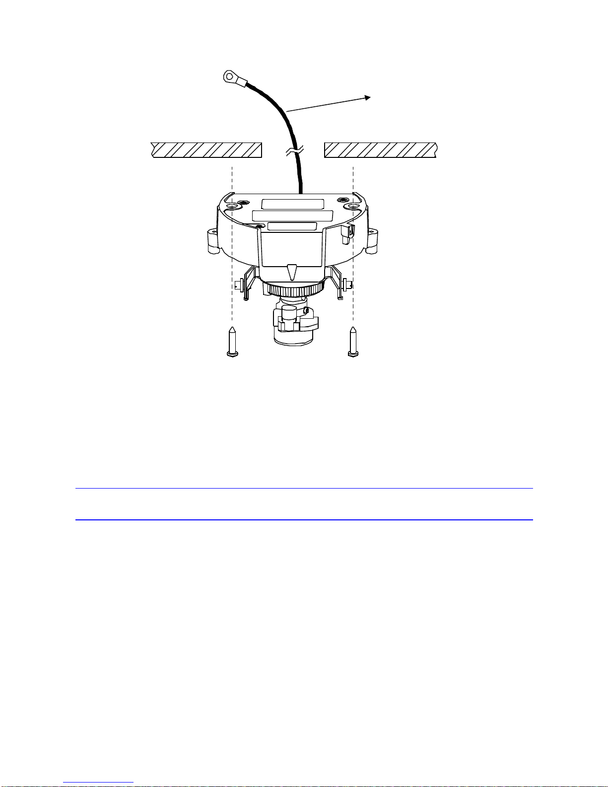
Connecting the Power Wiring............................................................................................3
Adjusting the Camera Position...........................................................................................4
Adjusting Zoom and Focus................................................................................................4
Mounting the Camera .......................................................................................................4
Locking the Camera..........................................................................................................6
Network Configuration ............................................................................................................6
Setting IP .........................................................................................................................6
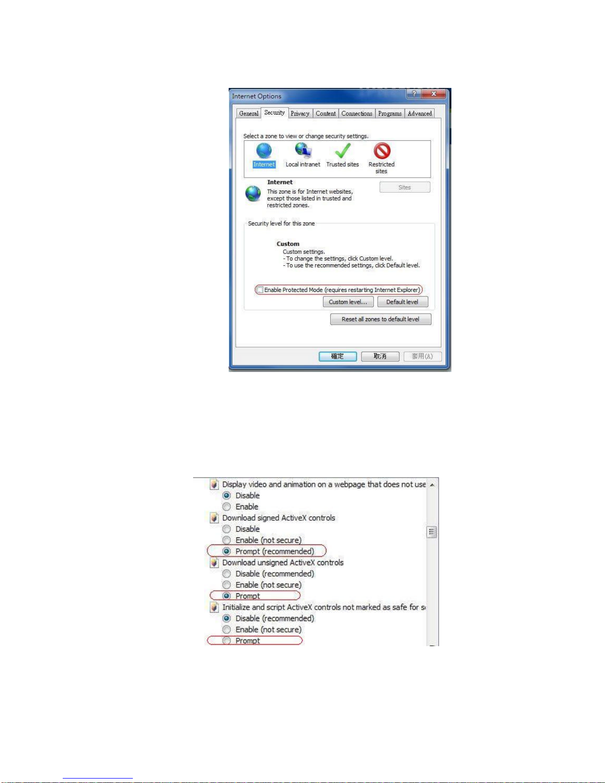
Connecting the Camera to a Personal Computer ................................................................6
Using “IP Finder” to Search Camera’s IP Address.............................................................10
2Notice of Use ......................................................................................................................10
3Warnings............................................................................................................................11
4Dimensions ........................................................................................................................11
5Specifications.....................................................................................................................12
nContents of this manual
•Windows and Internet Explorer are registered trademarks of
Microsoft Corporation in the U.S.
•Pentium is a registered trademark of Intel Corporation in the U.S.
•AMD is trademark of Advanced Micro Devices Inc. in the U.S.
•Product names of other companies described in this manual are
trademarks or registered trademarks of the respective companies.
Symbols such as ™, ® and © are omitted in this manual.
•Design, specifications and other contents described in this manual
are subject to change for improvements without prior notice.

2
1Introduction
Thank you for purchasing the camera. Before installing it, read the guide carefully and check the
model.
For more information, please refer to the INSTRUCTIONS on CD-ROM.
Unpack Everything
ŸFIXED HD IP DOME CAMERA
ŸWARRANTY CARD
ŸSAFETY PRECAUTIONS
ŸQUICK GUIDE
Ÿ2-PIN TERMINAL BLOCK for power input
Ÿ8-PIN TERMINAL BLOCK for alarm input/output
ŸCD-ROM containing INSTRUCTIONS and IP Finder software
ŸTEMPLATE : mounting template
Ÿ2 SCREW ANCHORs
Ÿ2 SCREWs
Preparation
The following tools might help you to complete the installation:
•Drill
•Screwdrivers
•Wire cutters
Camera Installation
Note All the installation and operations here should conform to your local electricity
safety rules.

3
Disassembling the Camera
•Gently remove the screw to take off camera housing (4)
•Remove the inner liner (3) by pulling it free of the two notches(2) in the housing.
•Set the camera housing (5) and liner (3) aside.
Connecting the Power Wiring
Connect the power supply cable to the power connectors.
Select one of the following options.
•For DC12V
Connect12V(-)to terminal =DC12V-
Connect 12 V(+) to terminal =DC12V+
•For AC24V
Connect24 V(~) cables to terminals ~AC24V.
•PoE
Connectthenetworkcableto theRJ45terminalusingaswitch.
Caution If using a DC supply, make sure the polarity is correct. Incorrect connection
may cause malfunction and / or damageto the camera.
Note
Connectors and field wiring terminals for external Class 2 circuits provided with
marking indicating minimum Class of wiring to be used. Class 2 shall be
marked adjacent to the field wiring terminals.

4
Adjusting the Camera Position
The dome camera has three axes for positioning the camera. Whilemonitoring thepictureonthe
monitor,adjustthecamerapositionasfollows:
•Pan Adjustment (A) For Wall Mount and Tilted Ceilings Rotate the lens base
(maximum360°) until you are satisfiedwith the field of view.
•Horizontal Rotation (B) Rotate 3D assembly in the base. Do not turn assembly more than
360°as this assembly may cause the internal cables to twist and disconnect or break.
•Tilt Adjustment (C) After loosening the thumbnuts, positionthe camera as desired, then
finger –tighten the thumbnuts to set the position.
Caution Donotturnthelensmorethan360°asthismaycauseinternal cablestodisconnect
orbreak.
Adjusting Zoom andFocus
•Loosen the zoom lever (D) / locking screw by turning it counter-clockwise.
•Rotate the zoom ring to achieve the desired picture.
•Loosen the focus lever (E) / locking screw by turning it counter-clockwise.
•Rotate the focus ring to adjust the focus.
•If re-adjustment is necessary, repeat the steps above.
•Retighten the zoom lever (D) /locking screw and the focus lever (E) / locking screw.
Caution Retighten the locking screws to prevent loss of adjustment.
Mounting the Camera
•Place the mounting template (supplied) on the mounting surface and mark the holes.
•Drill two holes, and then insert the screw anchors into the holes.
•Take off the camera housing.
•Connect theSafety Wire (Fall Prevention Wire, not supplied)to theceiling.

5
•Secure the camera bottom case (1) to the wall/ceiling with the TP4 x 15 mm tappingscrews,
supplied.
•Insert the power cable, LAN cable and Audio cables.
•Adjust the view angle (zoom, focus, and Horizontal Rotation).
To prevent the camera from falling off, ensure that it is connected to a firm place
(ceiling slab or channel) using a Safety Wire (Fall Prevention Wire is not
supplied).
Warning Pay also careful attention to the length, strength, wiring, and material (insulating
properties) of the fall prevention wire to be used. The length should be as short
as possible within the permissible range of the mounting length. The wire
should be strong enough to withstand the total weight of this product. (Pay also
attention to the finishing at the end of the wire.)
Caution Must be isolated camera and the wall/ceiling which are connected by the Safety
Wire (Fall Prevention Wire).
Note Dependingonthematerialofyourmountingsurface,youmay requiredifferent
screwsandanchorsthanthosesupplied.
Safety Wire (fall prevention
wire is not supplied).
Please tighten a safety wire
on a firm place as figure.

6
Locking theCamera
•Use soft, lint-free cloth to wipe the dome cover clean and remove fingerprints.
•Attach the inner liner and camera housing.
•Turn the power on after you have installed the camera.
Network Configuration
Setting IP
This is a network-based camera and must be assigned an IP address first.
The camera’s default IP address is192.168.0.2and sub mask is 255.255.255.0. To change
IP address, open Network Settings page described later.
If your network uses a DHCP server, an IP address can be assigned automatically from the
DHCP server by enabling DHCP in the Network Settings page described later.
Connecting the Camera to a Personal Computer
1. Connect the network cable to the camera and then turn on the camera’s power.
Safety Wire (Fall Prevention Wire, not
supplied)

7
2. Set the personal computer’s IP address. The camera’s default IP address is192.168.0.2
andsubmask is 255.255.255.0.
3. Check that the camera and computer are connected by Pinging the IP address you have
set. To do this, start a command prompt (Windows: from the Start Menu, select Program.
Then select Accessories and choose Command Prompt.) Type: Ping 192.168.0.2. If the
message “Reply from…” appears, it means the connection is done.
4. Start Internet Explorer and enter IP address: 192.168.0.2. A login window will appear.
Enter the default user name: admin and password: jvc to log in.
5. Images of the camera can be viewed through Internet Explorer. Before viewing, follow
these steps to enable the display.
a. Enable Cookies as shown below:
•In Internet Explorer, click Internet Options on the Tools menu.
•On thePrivacytab, move the settings slider to Low or Accept All Cookies.
•Click OK.
b. When a proxy server is used, click Internet Options on the Tools menu of Internet
Explorer, select Connect tab, click LAN button, and set proxy server.
c. Change Securityin Internet options as shown below:
•On tool menu, click Internet Option.
•Press theSecuritytab.
•If the camera operates inside the Intranet, click the Intranet icon. If the camera
operates on the Internet, click theInternet icon.

8
•In Windows 7 only, Click【Tools】è【Internet Options】è【Security】
Enable Protected Mode (require restarting Internet Explorer) èUnchecked
•Click Custom Level. This will open the Security Settings –Internet Zone
screen.
•Scroll down to the ActiveX controls and plug-ins radio buttons and set as
follows:
【Download signed ActiveX controls】èPrompt (recommended)
【Download unsigned ActiveX controls】èPrompt
【Initialize and script ActiveX not marked as safe for scripting】èPrompt
【Automatic prompting for ActiveXcontrols】èEnable

9
【RunActiveX controls and plug-ins】èEnable
【ScriptActiveXcontrols marked safe for scripting*】èEnable
•Press OK to save the settings. Close all Internet Explorer windows and start a
new window. This will allow the new settings to take effect.
6. Type your setting IP address into the browser.
7. Then you should be able to see the camera image screen.

10
Using “IP Finder” to Search Camera’s IP Address
The IP Finder is a tool which helps users to find VN-T16/216 seriesnetwork camerasin the LAN
which your computer is connected. Please note that IP Finder is only compatible with Windows 7,
windows Vista and Windows XP.
1. Insert the CD-ROMin the CD-ROM drive.
2. Copy theIP Finder’s folder to your computer.
3. Double click the IpFinder.exe in your computer’s IP Finder folder.AnIP Camera Finder
window will pop out. The window will display a list of IP cameras which you are using
currently.
4. Press Search to search cameras.
2Notice of Use
•This manual is designed for administrators and users of the network camera. Please read it
carefully before use. All requirements should be followed before using this camera.
•Keep this document for future reference.
•Please make sure the power source is DC12V / AC24V/ PoE. Only connect the camera to
thispowersystem.
•The camera must be installed on a solid mounting surface.
•Keep the camera and other accessories dry.
•We are not responsible for any damage caused by inappropriate use.
•Because the camera controls auto exposure by shutter speed, flicker can be shown by
fluorescent light. To reduce the flicker, please select PAL mode if the power is 50Hz, or NTSC
mode if the power is 60Hz. (Refer to INSTRUCTIONS “4 Overview of Navigation and
Controls”-“Video Type”)

11
3Warnings
Installation and maintenance should be performed only by qualified and experienced technicians
to conform to all local codes and to maintain your warranty.
DANGER! AC24V models require the use of CSA Certified/UL Listed Class 2 power adapters to
ensure compliance with electrical safety standards. Power over Ethernet (PoE) should meet the
IEEE 802.3af. PoE standard.
4Dimensions

12
5 Specifications
Operational Specifications
Image device 1/2.7-type Mega-pixel CMOS sensor
Sensitivity Color:0.6lx, B/W: 0.6lx (50%)
Day/Night Easy D/N
Auto Gain Control Off/On, selectable
White Balance ATW (2800K∼8500K) and Manual
Electric Shutter NTSC: 1/30~1/10000 sec
PAL:1/25~1/10000 sec
Noise Reduction Yes
3 Axis GimbalsYes
Motion detection Yes
Lens Type 1/3-type 3-9mm —F:1.2
BLC Yes
Audio Line in/out
Alarm 1 in / 1 out (Alarm out spec: 0.5A / AC120V max)
IP Specifications
Video Compression H.264 & MPEG4 & MJPEG
Video Streaming
Real time stream:
1080P H.264 or 720P H.264+D1 or D1+D1
Independent controllable framerate and bandwidth.
Constant or variable bitrate control
Resolution
NTSC: 1080P(1920 x 1080), 720P(1280 x 720),
D1(720 x 480), 4CIF(704 x 480), VGA(640 x 480),
CIF(352 x 240), QVGA(320 x 240)

13
PAL: 1080P(1920 x 1080), 720P(1280 x 720), D1(720
x 576), 4CIF(704 x 576), VGA(640 x 480), CIF(352 x
288), QVGA(320 x 240)
Image Frame Rate NTSC: Up to 30fps
PAL: Up to 25fps
Security Multiple user access levels with password
protection
Users 1 Administrator, 5 Users
Video Access from
Web Browser
Full control of all camera settings available to
administrator
Minimum Web
Browsing
Requirements
Windows XP or Windows 7 as OS,
Internet Explorer Version 6.0-8.0,
CPU: Intel Pentium IV X2 2.4 GHz or equivalent
AMD,
Memory: 1G or above
Supported Protocols
IPv4, HTTP, TCP, RTSP, RTP, ICMP, UDP, IGMP,
RTCP, FTP, DNS, DHCP, ARP
Network interface RJ-45, 100BASE-TX/10BASE-T,
FULL/HALF/Auto negotiation
Surveillance Protocol ONVIF Compatible (pass compliance test tool)
Onboard Storage SDHC (suggest class 10)
Electrical
Power Supply PoE IEEE 802.3af Class 0, DC12V, AC24V
Power Consumption PoE 0.13A, DC12V 550mA
Mechanical
Dimension Ø126mm x 106mm
Weight 490g

14
©2012 JVC KENWOOD Corporation
Connectors
Power Input: removable terminal block
Network: RJ45 connector
Audio In/out: removable terminal block
Alarm In/out: removable terminal block
Environmental
Operating
Temperature -10°C to 50°C
Operating Humidity 0% to 90%
Storage Temperature -20°C to 60°C
This manual suits for next models
1
Table of contents
Other JVC Security Camera manuals

JVC
JVC TK-C215VP4U - CCTV Camera User manual

JVC
JVC TK-C675BU User manual

JVC
JVC TK-C625 User manual

JVC
JVC VN-C215V4U - Fixed Ip Network Mini Dome User guide

JVC
JVC TK-C686E User manual

JVC
JVC TK-N1100 User manual

JVC
JVC KY-PZ510NWU User manual

JVC
JVC KY-F560U - 3-ccd Color Camera User manual

JVC
JVC VN-V686WPU User manual

JVC
JVC VN-C20 User guide

JVC
JVC VN-V25U VN-V26U User manual

JVC
JVC TK-C553 User manual

JVC
JVC TK-C920BU User manual

JVC
JVC TK-C675B User manual

JVC
JVC VN-T16U User manual

JVC
JVC VN-C215V4U - Fixed Ip Network Mini Dome User manual

JVC
JVC TK-C920BE User manual

JVC
JVC LWT0254-001B-H User manual

JVC
JVC VN-T216U User manual

JVC
JVC CU-V803 User manual