E-2
FOR USA AND CANADA
CAUTION:TO REDUCE THE RISK OF ELECTRIC
SHOCK. DO NOT REMOVE COVER (OR
BACK). NO USER-SERVICEABLE PARTS
INSIDE.REFER SERVICING TO
QUALIFIED SERVICE PERSONNEL.
The lightning flash wish arrowhead
symbol, within an equilateral triangle is
intended to alert the user to the pres-
ence of uninsulated “dangerous volt-
age” within the product's enclosure that
may be of sufficient magnitude to con-
stitute a risk of electric shock to per-
sons.
The exclamation point within an equi-
lateral triangle is intended to alert the
user to the presence of important op-
erating and maintenance (servicing)
instructions in the literature accompa-
nying the appliance.
RISK OF ELECTRIC SHOCK
DO NOT OPEN
CAUTION
INFORMATION (FOR CANADA)
RENSEIGNEMENT (POUR CANADA)
This Class B digital apparatus complies with
Canadian ICES-003.
Safety Precautions
Due to design modifications, data given in this
instruction book are subject to possible change
without prior notice.
WARNING:
TO REDUCETHE RISK OF FIRE OR
ELECTRIC SHOCK, DO NOT
EXPOSE THIS APPLIANCE TO
RAIN OR MOISTURE.
AVERTISSEMENT:
POUR EVITER LES RISQUES
D’INCENDIE OU D’ELECTRO-
CUTION, NE PAS EXPOSER
L’APPAREIL A L’HUMIDITE OU A
LA PLUIE.
INFORMATION FOR USA
Cet appareil numérique de la Class B est
conforme á la norme NMB-003 du Canada.
INFORMATION
This equipment has been tested and found to
comply with the limits for a Class B digital device,
pursuant to Part 15 of the FCC Rules.
These limits are designed to provide reasonable
protection against harmful interference in a
residential installation. This equipment generates,
uses, and can radiate radio frequency energy
and, if not installed and used in accordance with
the instructions, may cause harmfull interference
to radio communications. However, there is no
guarantee that interference will not occur in a
particular installation.
If this equipment does cause harmful interference
to radio or television reception, which can be
determined by turning the equipment off and on,
the user is encouraged to try to correct the
interference by one or more of the following
measures:
●Reorient or relocate the receiving antenna.
●Increase the separation between the equipment
and receiver.
●Connect the equipment into an outlet on a circuit
different from that to which the receiver is
connected.
●Consult the dealer or an experienced radio/TV
technician for help.
CAUTION
CHANGES OR MODIFICATIONS NOT
APPROVED BY JVC COULD VOID USER’S
AUTHORITY TO OPERATE THE EQUIPMENT.
THIS DEVICE COMPLIES WITH PART 15 OF
THE FCC RULES.
OPERATION IS SUBJECT TO THE FOLLOWING
TWO CONDITIONS: (1) THIS DEVICE MAY NOT
CAUSE HARMFUL INTERFERENCE, AND (2)
THIS DEVICE MUST ACCEPT ANY
INTERFERENCE RECEIVED, INCLUDING
INTERFERENCE THAT MAY CAUSE
UNDESIRED OPERATION.
English
E-3
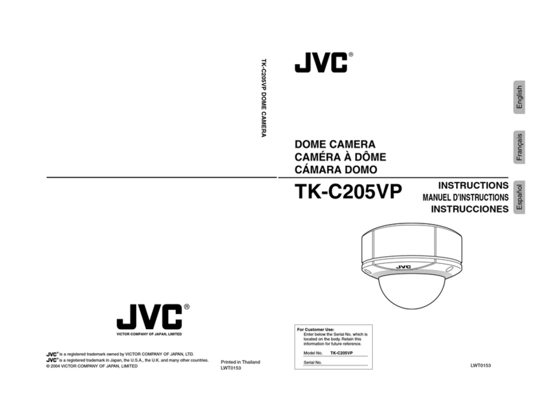
Thank you for purchasing this product.
(These instrustions are for TK-C205VPU and TK-C205VPE)
Before beginning to operate this unit, please read the instruction manual
carefully in order to make sure that the best possible performance is obtained.
Introduction
Features
The unit can be installed directly
outdoors since the dust/drip-proof
structure (IP66) is unaffected by
rain.
The unit is designed to withstand
substantial shock.
The camera uses a high-resolution
380,000 pixel (U type) / 440,000
pixel (E type), high-sensitivity CCD
to realize high picture quality with
horizontal resolution of 535 TV lines
and S/N50dB.
Dome-type design allows applica-
tion in various locations.
Built-in backlight compensation
feature to improve the quality of
video taken under backlight
conditions.
A4inch square electrical box
compatible
The camera can be set to automati-
cally switch the image to black and
white when the brightness of the
subject decreases. This feature is
useful for monitoring in darkness.
Contents
Introduction
Features ......................................... 3
Contents ......................................... 3
Safety Precautions ......................... 4
Operating Precautions ................... 5
Names and Operations of Parts
Camera unit ................................... 6
Main unit bottom/side/top .............. 8
Installation and connection
System diagram ............................. 9
Installing the camera...................... 9
Mounting the base ....................... 10
Connect the Cables to the Base ...
12
Mount the Camera unit to
the Base ....................................... 13
Before Adjusting the Camera ...... 14
Adjusting the Lens and Camera
Angle ............................................ 14
Attach the Dome cover ................ 15
When Installing the Camera Using
the Conduit Hole (side) ................ 16
When Installing the Camera Using
the Electrical Box ......................... 17
When installing the camera to a
ceiling without piping ................... 18
Others
About White-spot correction ........ 19
Specifications ............................... 20
