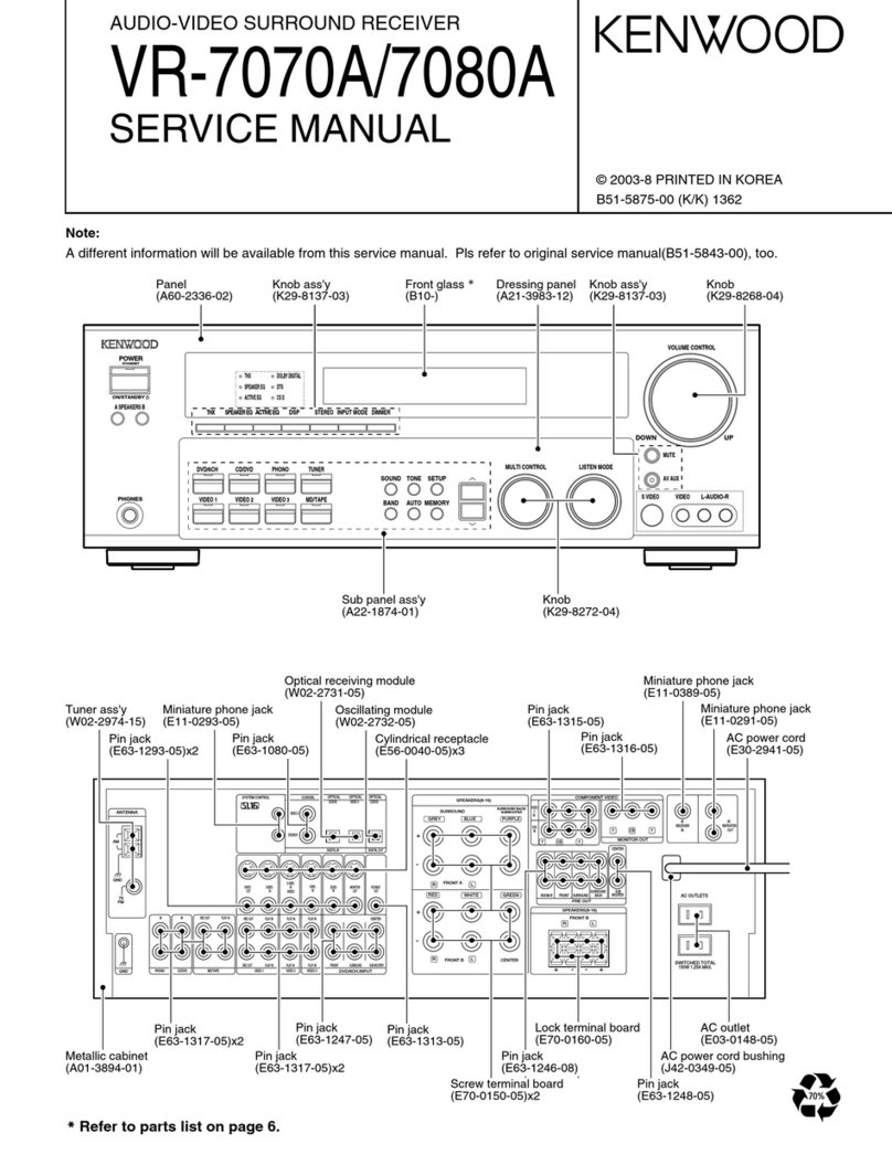
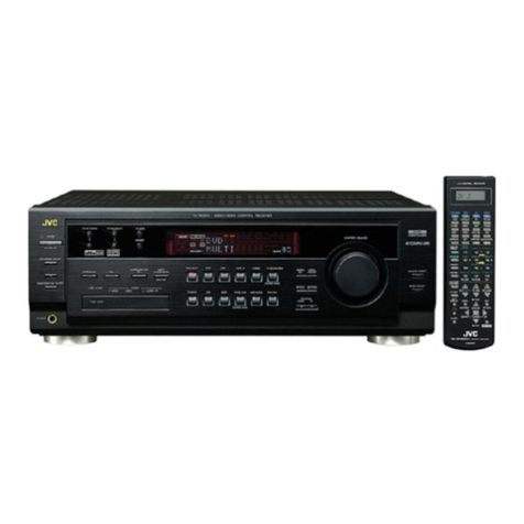
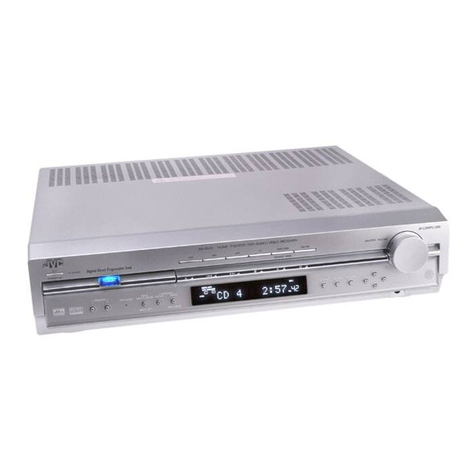
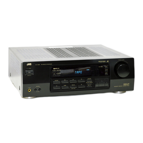
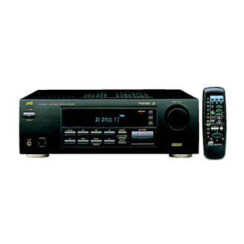
JVC RX-504VBK User manual

RX-504VBK/RX-504VLBK
RX-505VTN/RX-505VLTN
JVC
ERVICE
MANUAL
RX-504VBK/RX-504VLBK
move.
no.
RX-SOSVTN/RX-SOSVLTN
0040
10
010
**O
O40
ed
3S
pag
id
¢
2.
io)
fo)
6
°
3
x
©
4
eo
=e
je
i=)
e5
et
de
OO
|
PPrAABI
I I
yAliy
WoW
WS
belT
CEN
Il||/Remote
TllRemote
Ill
Control
Component
Note:
RX-504VBK/RX-504VLBK
and
RX-505VTN/RX-505VLTN
are
competely
same
in
their
structure,
except
for
their
outlook
colours.
Contents
Safety
Precaution
.............cceccceeseeee
sense
een
eeneneeeees
1-2
Power
Amplifier
Adjustment
Procedures
...............
1-36
Instruction
BOOk
..............:eceeeeeesen
eens
eseceneneetereees
1-3
Timing
Chart...
:
ieee
ccccaciseicetseecdeseectese
ni
staseessaeenet
1-36
Description
of
Major
ICs
..............c::eceeeeseeeeee
renee
1-24
Block
Diagram
..............:ccccceseeccseeeeeneeeesecneeesseners
1-37
Internal
Block
Diagram
of
Other
ICs
.................006
1-30
Schematic
Diagrams
.................:ccsseeseeeevereeeee
Insertion
Internal
Wiring
of
FL
Display
................:.:eeeeeeeeeeee
1-33
Printed
Circuit
Board
................2..c:ceeeeeeeeen
nee
Insertion
Disassembly
Procedures
..............::.ceceeeeeeeeneneeoees
1-34
Connection
Diagram
............ccecceeeeeeeeneneeeneeee
Insertion
FM/AM
Tuner
Alignment
Procedures
.................55+
1-35
Parts:
LiSt:\si20.c.tewedcicteracencicedeidensvetectecsevanegaee
Insertion
Mo.
20220
Jan.
1991

RX-504VBK/RX-504VLBK
RX-505VTN/RX-505VLTN
Safety
Precautions
1.
The
design
of
this
product
contains
special
hardware
and
many
circuits
and
components
specially
for
safety
purposes.
For
continued
protection,
no
changes
should
be
made
to
the
original
design
unless
authorized
in
writing
by
the
manufacturer.
Replacement
parts
must
be
identical
to
those
used
in
the
original
circuits.
Services
should
be
performed
by
qualified
personnel
only.
2.
Alterations
of
the
design
or
circuitry
of
the
product
should
not
be
made.
Any
design
alterations
of
the
product
should
not
be
made.
Any
design
alterations
or
additions
will
void
the
manufacturer’s
warranty
and
will
further
relieve
the
manufacture
of
responsibility
for
personal
injury
or
property
damage
resulting
therefrom.
3.
Many
electrical
and
mechanical
parts
in
the
products
have
special
safety-related
characteristics.
These
characteristics
are
often
not
evident
from
visual
inspection
nor
can
the
protection
afforded
by
them
necessarily
be
obtained
by
using
replacement
components
rated
for
higher
voltage,
wattage,
etc.
Replacement
parts
which
have
these
special
safety
characteristics
are
identified
in
the
Parts
List
of
Service
Manual.
Electrical
components
having
such
features
are
identified
by
shading
on
the
schematics
and
by
(A\)
on
the
Parts
List
in
the
Service
Manual.
The
use
of
a
substitute
repalcement
which
does
not
have
the
same
safety
characteristics
as
the
recommended
replacement
parts
shown
in
the
Parts
List
of
Service
Manual
may
create
shock,
fire,
or
other
hazards.
4.
The
leads
in
the
products
are
routed
and
dressed
with
ties,
clamps,
tubings,
barriers
and
the
like
to
be
separated
from
live
parts,
high
temperature
parts,
moving
parts
and/or
sharp
edges
for
the
prevention
of
electric
shock
and
fire
hazard.
When
service
is
required,
the
original
lead
routing
and
dress
should
be
observed,
and
it
should
be
confirmed
that
they
have
been
returned
to
normal,
after
re-assembling.
5.
Leakage
currnet
check
(Electrical
shock
hazard
testing)
After
re-assembling
the
product,
always
perform
an
isolation
check
on
the
exposed
metal
parts
of
the
product
(antenna
terminals,
knobs,
metal
cabinet,
screw
heads,
headphone
jack,
contorl
shafts,
etc.)
to
be
sure
the
product
is
safe
to
operate
without
danger
of
electrical
shock.
Do
not
use
a
line
isolation
transformer
during
this
check.
@
Plug
the
AC
line
cord
directly
into
the
AC
outlet.
Using
a
“Leakage
Current
Tester",
measure
the
leakage
current
from
each
exposed
metal
parts
of
the
cabinet,
particularily
any
exposed
metal
part
having
a
return
path
to
the
chassis,
to
a
known
good
earth
ground.
Any
leakage
current
must
not
exceed
0.5mA
AC
(r.m.s.).
®@
Alternate
check
method
Plug
the
AC
line
cord
directly
into
the
AC
outlet.
Use
an
AC
voltmeter
having,
|
,000
ohms
per
volt
or
more
sensitivity
in
the
following
manner.
Connect
a
1,500Q
10
W
resistor
paralleled
by
a
0.15
»F
AC-type
capacitor
between
an
exposed
metal
part
and
a
known
good
earth
ground.
Measure
the
AC
voltage
across
the
resistor
with
the
AC
voltmeter.
Move
the
resistor
connection
to
each
exposed
metal
part,
particularly
any
exposed
metal
part
having
a
return
path
to
the
chassis,
and
meausre
the
AC
voltage
across
the
resistor.
Now,
reverse
the
plug
in
the
AC
outlet
and
AC
VOLTMETER
(Having
1000
ohms/volts,
or
more
sensitivity.)
Piace
this
probe
ort
repeat
each
measurement.
Any
voltage
each
exposed
measured
must
not
exceed
0.75
V
AC
(r.m.s.).
15000
10W
metal
part.
This
corresponds
to
0.5
mA
AC
(r.m.s.).
Good
earth
ground
Warning
.
This
equipment
has
been
designed
and
manufactured
to
meet
international
safety
standards.
_
It
is
the
legal
responsibility
of
the
repairer
to
ensure
that
these
safety
standards
are
maintained.
.
Repairs
must
be
made
in
accordance
with
the
relevant
safety
standards.
_
It
is
essential
that
safety
critical
components
are
replaced
by
approved
parts.
_
lf
mains
voltage
selector
is
provided,
check
setting
for
local
voltage.
1-2
(No.20220)

Specifications
AMPLIFIER
SECTION
Output
power
(CD
INSP.
OUT)
:(For
the
U.S.A.
and
Canada)
80
watts
per
channel,
min.
RMS,
both
channels
driven
into
8
ohms
from
20
Hz
to
20
kHz,
with
no
more
than
0.03%
total
harmonic
distortion.
(For
other
areas)
70
watts
per
channel,
min.
RMS,
both
channels
driven,
into
8
ohms
from
20Hz
to
20kHz,
with
no
more
than
0.03%
total
harmonic
distortion.
70
wattes
per
channel,
min.
RMS,
both
channels
driven,
into
8
ohms
at
1kHz(DIN).
20
wattes
channel,
min.
RMS,
into
8
ohms
at
1kHz,
with
no
more
than
0.7%
total
harmonic
distortion.
:
0.03%
at
80
watts
Rear
channels
intermodulation
distortion
input
sensitivity
/
impedance
PHONO
:2.5mV/47k
ohms
TAPE
1
PLAY,CD
:
200mV
/33k
ohms
TAPE
2
PLAY,
VIDEO
VCR
PLAY
Recording
output
level
:
200mV
Frequency
response
PHONO
(RIAA
equalization)
TAPE
1
PLAY,
CD
TAPE
2
PLAY,
VIDEO
VCR
PLAY
2:20
Hz
—
20kHz
+0.5dB
:10Hz
—
30kHz
+1dB
Signal-to-noise
ratio
PHONO
:
71dB
(‘66IHF)
78
dB
(‘78
IHF,
REC
OUT)
66
dB
(DIN)
TAPE
1
PLAY,
:
91
dB
(‘66IHF),
85
dB
(‘78
IHF)
TAPE2
PLAY,
CD
67dB
(DIN)
VIDEO
VCR
PLAY
S.E.
A.
graphic
equalizer
Center
frequencies
:
63Hz,
160Hz,
400Hz,
1kHz,
2.5kHz,
6.3kHz,
16kHz
Control
range
:
10dB
Tone
controls
BASS
:*8dB
(100Hz)
TREBLE
:+8dB
(10kHz)
FM
TUNER
SECTION
(IHF)
>
87.5
MHz
—
108.0
MHz
:
Mono
10.8
dBf
(0.95V/75
ohms)
Tuning
range
Usable
sensitivity
50
dB
quieting
:
Mono
16.3dBf
(1.84V/75
ohms)
sensitivity
Stereo
38.3
dBf
(22.5
nV
/75
ohms)
Signal-to-noise
ratio
:
Mono
80
dB
(IHF-Anet,
at
85dBf)
Stereo
73
dB
Total
harmonic
distortion
(1
kHz)
:
Mono
0.15%
Stereo
0.2%
Frequency
response
:30Hz
—
15kHz,(+0.5
dB,
-3
dB)
Capture
ratio
(
at
85
dBf)
:1.5dB
Alternate
channel
selectivity
:
60dB(+
400kHz)
:
85dB
(at
98
MHz)
:
40
dB
(at
1
kHz)
IF
response
ratio
Stereo
separation
RX-504VBK/RX-504VLBK
RX-505VTN/RX-505VLTN
AM
TUNER
SECTION
MW
Tuning
range
Channel
space
Area
9kHz
10kHz
530kHz~1710kHz
522kHz~
1629kHz
522kHz~1629kHz
522kHz~1629kHz
531kHz~
1602kHz
530kHz~1600kHz
Sensitivity
Loop
antenna
>
300
nV
/m*
External
antenna
730
«V*
Signal-to-noise
ratio
:
50
dB*
(100mV/m)
Selectivity
:
25
dB”
(+9kHz,
+10
kHz)
LW
(RX-504L/505L
)
Tuning
range
SC
ee
eee
|
Austria
|
|
OtherArea
|
Sensitivity
Loop
antenna
>
6004V
/m
at
245kHz
External
antenna
:100uV
at
245kHz
Signal-to-noise
ratio
(100
mV
/m)
:
50dB
at
245kHz
Selectivity
>
32dB
+
9kHz
at
245kHz
VIDEO
SECTION
Output
signal
level
>
1Vp.p
(at
1
Vp.p
input)
(VCR
REC,
MONITOR
OUT)
Impedance
:
75
ohms,
unbalanced
Synchronization
:
Negative
Signal-to-noise
ratio
>
45dB
Crosstalk
:
45d0B
(3.58MHz)
GENERAL
Dimensions
:17-3/16"
x5"
x
13”
(WxHxD)
(435
x
127
329
mm)
Weight
:
21.6
Ibs.
(9.8
kg)
*
Measured
at
1,000
kHz
or
999kHz
Design
and
specifications
subject
to
change
without
notice.
POWER
SPECIFICATIONS
:
Power
Line
Voltage
&
Frequency
Ciprsiimptio
4
n
U.S.A.
Canada
AC120V~,
60Hz
230
watts,
310
VA
Continental
Europe
AC230V~,
5OHz
U.K.
Australia
AC240V~,
50Hz
Al
~~
ihap
nies
€110/127/220/240V
selectable,
50/60Hz
(NoZ0220)
1-3

RX-504VBK/RX-5O4VLBK
RX-505VTN/RX-505VLTN
YolUl
gox-¥m
Oxo)
nal
ole)
ay)
a)
am
Oxesalay-xoa
tle)
ayy
Switch
the
power
off
when
connecting
any
cables.
Turntable
CD
player
Vi0EO
N
aes
VIO
OUT
VCR
DAT
deck
or
cassette
Cassette
deck deck
x
—_—o
=
—
—;
=a
LINE
IN
LINE
OUT
LINE
IN
LINE
OUT
(Analogue)
(Analogue)
Since
mutual
interference
between
video
and
audio
components
can
cause
noise
and
distorded
pictures,
you
are
recommended
to
use
Coaxial
cable
for
the
TV/video
antenna
Video
disc
player
To
TV
antenna
@GND
©
AUDIO
terminals
(PHONO,
CD,
TAPE
1,
TAPE
2,
VCR,
VIDEQ)
@
VIDEO
terminals
(VCR,
VIDEO}
@
COMPU
LINK-1/SYNCHRO
terminais
Connect
to
JVC
components
provided
with
COMPU
LINK-1/SYN-
CHRO
terminals
for
the
COMPU
LINK
control
system
function
P-OYAABIE
F
IATL
WoUFIVET
WS
inl
VEN
I!/Remofe
//II
Control
System
COMPU
LINK
is
a
computer-linked
system
by
which
individual
JVC
audio
and/or
video
components
are
controlled
via
a
com-
puter.
For
further
details,
see
page
16.
1-4
(No.20220)
Notes:
@
When
connecting
components,
connect
their
left
and
right
chan-
nels
correctly.
If
channels
are
reversed,
the
stereo
effect
will
be
degraded.
@
The
AC
OUTLETS
do
not
supply
power
when
the
power
switch
is
turned
off.
Do
not
connect
equipment
requiring
more
than
the
outlet’s
rated
value.
@
Do
not
connect
the
remote
cable
when
connecting
the
JVC
cas-
sette
deck
having
COMPU
LINK-1/SYNCHRO
terminals
to
the
TAPE
2
terminals.
@
When
a
JVC
DAT
deck
having
COMPU
LINK-1/SYNCHRO
termi-
nals
is
used,
be
sure
to
connect
it
to
the
TAPE
2
terminals
and
also
connect
the
remote
cable.
®@
Connect
a
turntables
using
a
moving
magnetic
(MM)
type
car-
tridges
to
the
PHONO
terminals.

elaTh
coy
am
Oxeyeny
exe)
ar-lay
am
Ore)
alal-rentleyarsy
*
in
case
the
JVC's
monnor
TV
has
the
multi-input
function,
connect
to
the
“VIDEO
1”
terminal
VIDEO
IN
(EXT
IN*)
mc
far
'
TAPE
Open
the
speaker
terminal
Clamp
the
wire
by
by
pressing
the
lever
and
resetting
the
lever.
insert
the
stripped
end
ot
the
cord
@
MONITOR
OUT
terminal
©
SPEAKERS
1,
2
terminals
@
SURROUND
SPEAKERS
terminals
RX-504VBK/RX-SOAVLBK
RX-505VTN/RX-505VLTN
iFront
speakers)
Speakers
2
(Front
speakers)
Speakers
4
(Rear
speakers)
Surround
speakers
Notes:
@
Connect
speakers
with
the
correct
polarity:
(+)
to
(+)
and
(—)
to{—}.
Reversed
polarity
wil!
Gegrade
the
stereo
effect.
Be
care
ful
to
prevent
adjacent
speaker
wires
from
touching
each
other.
@
Use
sneakers
with
[ne
correct
impedance.
The
correct
imped
ance
1S
indicated
on
the
rear
panel
of
the
receiver.
@
When
using
surround
speakers,
be
sure
to
connect
both
the
night
and
left
speakers,
connecting
only
one
speaker
will
not
generate
sound
(No.2022
0)
1-5

RX-504VBK/RX-504VLBK
RX-505VTN/RX-505VLTN
Installation
of
Loop
Antenna
Fig.
2|
Fig.
3
Insert
in
the
direction
of
arrow.
Fig.
1]
Fig.
5
Fig.
6
AM
antennas
Figure
1:
How
to
assemble
the
AM
loop
antenna
Figure
2:
AM
loop
antenna
This
antenna
is
for
the
reception
of
local
AM
broadcasts.
Figure
2:
AM
external
antenna
If
AM
reception
is
unsatisfactory,
connect
an
external
AM
antenna
(single-wire
antenna)
to
the
AM
EXT
terminal
Figure
3:
Connection
of
AM
antenna
@)
Open
antenna
terminals
levers
(2)
Plug
cords
into
the
terminals
(3)
Close
the
levers.
Figure
4:
Noise
and
interference
Change
the
direction
of
the
loop
antenna,
or
re-install
it
in
a
better
psition
‘f
the
reception
is
noisy.
75-ohm
antenna
with
coaxial
FM
feeder
antenna
AM
external
antenna
Notes:
@
If
the
provided
loop
antenna
!s
not
connected
or
an
uninsulated
antenna
wire
tcuches
the
rear
panel,
it
will
be
impossible
to
receive
AM
broadcasts
@
When
installing
an
e.tersal
AM
antenna,
leave
the
AM
loop
an-
tenna
connected
FM
antennas
:
2
Figure
5:
75-ohm
FM
antearta
ith
coatfa
Loosen
the
screws
on
the
brackei
and
inseri
‘he
cable
through
the
ring
from
below.
Connect
the
strippea
7ore
to
tne
upper
terrninail
then
Anica
athe
tighten
the
ring.
The
ring
is
the
antenna
ground
Figure
6:
FM
Feeder
antenna
Connect
to
the
FM
300
Q
terminal.
Make
sure
the
feeder
antenna
wires
do
not
touch
any
other
terminais.
R
z
1-6
(No.20220)

RX-504VBK/RX-504VLBK
RX-505VTN/RX-SO5VLTN
Display
window
®
@
@
POWER
(ON/STANDBY)
Press
this
button
to
turn
the
power
ON.
Press
again
to
turn
the
power
off
and
activate
the
STANDBY
mode.
The
STANDBY
indi-
cator
will
light
A
small
amount
of
power
(5
watts)
is
consumed
in
the
STAND-
BY
mode.
To
turn
the
power
off
completely,
disconnect
the
power
cord
from
the
wall
outlet.
Preset
data
1s
retained
in
memory
while
the
power
cord
is
plugged
into
the
wall
outlet.
If
the
power
cord
is
disconnected
or
a
power
failure
occurs,
data
is
retained
for
two
or
three
days.
©
SPEAKERS
1,
2
Turns
speakers
1
and
2
ON
or
OFF.
©
PHONES
Plug
headphones
into
this
jack.
If
you
want
to
hear
from
the
head-
phones
alone,
turn
OFF
speakers
1
and
2
@
cSRP
COMPU
LINK
SOURCE
RELATED
PRESET
SYSTEM
feature
CSRP:
Turns
the
CSRP
feature
ON
or
OFF
MEMORY:
Stores
CSRP
data
in
memory.
©
CHARACTER
INPUT
Use
the
following
keys
to
assign
tities
or
other
data
to
the
S.E.A
patterns
or
to
TUNER
channels
you
have
preset
°
CHARACTER
«
ENTER
«
DOWN,
UP
For
details,
see
‘‘Entering
Characters’
@
LOUDNESS
Turns
LOUDNESS
ON
or
OFF.
The
ON
position
makes
up
for
loss
of
the
human
auditory
sensatian
when
the
sound
volume
is
low
@
BALANCEL,
R
Adjusts
the
volume
balance
between
the
left
and
right
speakers.
@
DIGITAL
SURROUND
Use
these
keys
when
you
playback
with
a
surround
sound
effect.
e
REAR
LEVEL
©
DELAY
TIME
¢
SURROUND
¢
INPUT
BALANCE
*
HALL,
STADIUM
¢
DOLBY
SURROUND
@
TUNER
Use
the
following
keys
to
listen
to
AM
or
FM
broadcasts:
¢
MEMORY
¢
TUNING
<,>
e
AUTO
MEMORY~
¢
1-10,
+10
(Tuner
numeric
keys)
¢
FM
MODE/MUTE
For
details,
see
‘‘Listening
to
AM
or
FM
broadcasts’’
@
MUTE
Turns
sound
ON
or
OFF
temporarily.
@
VOLUME
<
,>
Adjusts
the
volume
of
sound
from
the
speakers
or
headphones.
@
REMOTE
SENSOR
Receives
signals
from
the
remote
control
unit
@
RECEIVED
and
POWER
STANDBY
indicator
Lights
when
signals
are
received
from
the
remote
control
unit
or
when
the
machine
is
in
the
STANDBY
mode
@
SOURCE
Use
the
following
keys
lo
select
lo
select
sources:
e
VCR
e
FM
¢
VIDEO
«
AM
¢
PHONO
*
TAPE
1
«CD
°
TAPE
2
(alternates
between
ON
and
OFF)
@®
SEA
Use
the
following
keys
for
the
S.E.A.
Graphic
Equalizer:
©
SEA
¢
MEMORY
e
FLAT
e
PRESET
¢
REVERSE
e
LEVEL
<
,
>
¢
DISPLAY
e
FREQUENCY
<
,
>
For
details,
see
‘‘Using
the
S.E.A.
graphic
equalizer’
©
Surround
mode
indicator
Shows
the
surround
mode
selected.
(No.20220)
1-7

RX-504VBK/RX-5O04VLBK
.
RX-505VTN/RX-SO5VLTN
—
Before
Operating
—
Before
plugging
the
power
cord
into
an
AC
outlet,
check
to
be
sure
the
individual
components
are
connected
correctly.
1.
Turn
the
POWER
to
ON.
4.
Adjust
the
VOLUME
and
BALANCE
keys
to
your
taste.
VOLUME
POWER
BALANCE
ON/STANDBY
.
.
.
@
.
. .
a
“8
Morac
mre
i
oe
Pact
Pe
eI
wwe
|
i
=.
PLP
deh
Note:
These
keys
vary
their
settings
while
they
are
being
pressed.
The
dis-
The
display
window
lights
up.
play
normally
shows
VOLUME.
It
will
change
to
BALANCE
for
about
5
seconds
when
the
BALANCE
keys
are
pressed.
Note:
lf
a
malfunction
occurs
when
the
power
is
ON;
unplug
the
power
5.
Press
the
LOUDNESS
and
MUTE
keys
as
needed.
cord
and
then
plug
it
in
again.
@
Press
to
make
up
for
loss
of
the
human
auditory
sensation
when
2.
Selecta
speaker
system
by
pressing
one
of
the
SPEAKERS
keys.
the
sound
volume
is
low.
Lous
VOLUME
1
SPEAKERS
2
—
BALANCE
ON
OFF
a
LOUDNESS
@
Press
to
temporarily
cancel
sound
output.
Note:
If
speakers
are
not
connected
to
both
SPEAKERS
1
and
2
terminalis,
MUTE
do
not
turn
ON
both
speaker
systems
as
that
would
suppress
sound
>_—-
—
output.
;
NA
i
|
|
i
3.
Press
one
of
the
SOURCE
keys
for
the
desired
source.
\
7
To
release
it
press
the
MUTE
key
again.
co
|
|
|
Note:
i_
ti]
The
MUTE
key
is
reset
when
the
VOLUME
or
BALANCE
keys
are
pressed.
1-8
(No.20220)

RX-504VBK/RX-504VLBK
RX-505VTN/RX-505VLTN
Listening
to
AM
or
FM
Broadcasts
®@
Selecting
a
Station
1.Press
the
AM
or
FM
key.
*M
AM
2.
Use
the
TUNING
keys
to
find
a
station.
<<
TUNING
>
Each
time
the
TUNING
keys
are
pressed,
the
frequency
is
varied
in
steps
of
10
kHz
for
AM
and
0.1
MHz
for
FM.
The
setting
will
vary
continuously
while
the
keys
are
pressed
and
held.
FM
Oh
TC
owe
ti
fl
Auto-tuning
starts
when
the
TUNING
keys
are
released
and
stops
when
a
Station
is
tuned.
To
halt
auto-tuning,
press
a
TUNING
key.
3.
The
TUNED
indicator
will
lignt
when
a
station
is
tuned
in
correctly.
vue
Adjust
the
antenna
if
the
indicator
does
not
iight
@
While
tuning
in
an
FM
station,
press
the
FM
MODE/MUTE
key
to
light
the
MUTE/AUTO
indicator,
this
cuts
out
inter
station
noise
while
tuning
@
The
STEREO
indicator
will
light
when
an
FM
stereo
station
!s
tuned
in
correctly.
If
the
FM
stereo
station
is
weak
and
noisy,
press
the
FM
MODE/MUTE
key
again
to
turnotf
the
MUTE/AUTO
indicator
to
improve
reception
(broadcast
becomes
monaural).
A
A
en
De el
ect
Fh
as
a
9
ea
|
orem
|
@
Presetting
Stations
You
can
preset
a
total
of
40
AM
and
FM
station
(CH
1
through
CH
40).
1.
Tune
in
the
desired
station
with
the
TUNING
keys.
MUT!
rs
2.
Press
the
MEMORY
key
to
light
its
indicator.
MUTE
MEMORY
STEREO
Mure
MEMORY
Cl
FM
.
~
“ch
3.
Enter
the
channel
number
with
numeric
keys
while
the
indicator
is
on
(for
about
5
seconds).
MUT!
TUNED]
[STEREO]
MUTE
MP
deg
Ich
@
|f{
the
indicator
turns
off
before
you
enter
the
channel
number,
press
the
MEMORY
key
again.
4.
Repeat
this
procedure
to
preset
other
channels.
(No.20220)
1

RX-504VBK/RX-504VLBK
RX-505VTN/RX-505VLTN
#
AUTO
MEMORY
The
auto-memory
feature
scans
frequencies
upward
and
presets
sta-
tions
as
they
are
tuned,
in
ascending
channel
number
order.
1.
Using
the
TUNING
keys,
select
the
frequency
from
which
you
want
auto-memory
to
start
(the
lower-limit
frequency).
2.
Press
the
AUTO
MEMORY
key
to
light
its
indicator.
AUTO
sam
AUTO
et
Pe
oi
"
Bal’.
deh
~~
ch
Enter
the
starting
channel
number
with
the
numeric
keys
while
the
indicator
is
on
(about
5
seconds)
_—
nS
FM
CI
OTe
\
ie
ae
as
ee
jo
@
If
the
indicator
turns
off
before
you
enter
the
channel
number,
press
the
AUTO
MEMORY
key
again.
3.
The
auto-memory
feature
starts
scanning
frequencies
upward.
The
TUNED
indicator
will
light
when
a
station
is
tuned,
with
the
channel
number
blinking
(for
about
5
seconds)
AUTO
Fil)
Wte
A
—
cogs
/
_/
of.
Ll
ich
4.
The
presetting
is
complete
when
the
MEMORY
indicator
is
lit
[MEMORY]
[TUNED]
[STEREO
rts
FM
EE
ae
ah
hcg
leh
This
continues
until
the
upper-limit
frequency
ts
reached
or
all
40
channels
are
filled
Note:
If
you
do
nat
want
to
preset
a
station,
resume
scanning
by
pressing
the
AUTO
MEMORY
key
while
the
channel
number
is
blinking.
To
halt
the
auto-memory
feature,
press
any
TUNER
key
other
than
the
AUTO
MEMORY
key.
1-10
(No.
20220)
@
Recalling
preset
channels
1.
Press
numeric
keys
to
select
a
preset
chanel.
fi
2
‘
VRE
[URED]
[aTERED)
MUTE
Lt
/
=
-
ae
Lil
;
=.
lene
Be
i
@
To
indicate
numbers
1
through
10,
simply
press
the
appropriate
keys.
To
indicate
numbers
over
10,
press
the
appropriate
combination
of
keys.
Examples;
To
indicate
17,
press
‘+
10",
then
‘’7"’.
To
indicate
20,
press
‘+10’,
then
‘'10’’.
To
indicate
26,
press
‘‘+
10"'
twice,
then
‘'6”
To
indicate
40,
press
‘'+10"'
three
times,
then
''10’'.

RX-504VBK/RX-504VLBK
RX-505VTN/RX-505VLTN
Playing
Back
with
a
Surround-sound
Effect
The
soundtracks
of
the
video
software
bearing
DOjecsy
sursouna;
park
includes
the
same
encoded
surround
information
as
found
in
the
Dolby
Stereo
films.
As
the
RX-505VBK
incorporates
4
Dolby
Surround
decoder
circuit,
you
can
get
the
Dolby
Stereo
theatre's
ambience
and
effect,
when
watching
these video
sources
at
home.
SURROUND
MODE
There
are
three
surround
modes
DOLBY
SURROUND:
This
mode
produces
a
live
three-dimensional
acousitc
effect
when
playing
back
a
program
source
encoded
with
Dolby
Surround.
HALL:
Produces
the
expanding
surround
sound
effect
such
as
you
would
experience
in
a
music
hail.
STADIUM:
Provides
the
powerful
dynamic
surround
sound
effect
of
stadium
music.
@
Select
DOLBY
SURROUND
when
you
use
video
software
with
the
DO
{oorsrsurrcune;
mark.
For
ordinary
stereo
sources
use
HALL
or
STADIUM.
SPEAKER
LAYOUT
EXAMPLE
FRONT
SPEAKERS
It
is
recommended
that
antimagnetic
speakers
be
installed
near
the
TV
monitor
REAR
SPEAKERS
1.
Set
the
SURROUND
key
to
ON.
SURROUND
SURROUND
2.
Select
the
Surround
mode:
DOLBY
SURROUND,
HALL,
or
STADIUM.
<
If
you
select
‘‘DOLBY
SURROUND”
>
DOLBY
SURROUND
Ste
eee
A
-C73-DC
[o0c8y
suarouns
}
“UN
os
ats
oar
=
3.
Play
back
the
source.
(No.20220)
1-'71

RX-504VBK/RX-504VLBK
RX-SOSVTN/RX-505VLTN
“=
REAR
LEVEL
>
‘SURROUND
DOLBY
SURROUND
HALL
STADIUM
INPUT
BALANCE
|
CJ
C4
|
Nacsa
cis
cel
a
=
Adjustment
Make
the
following
adjustment
to
get
maximum
out
of
the
surround
sound
effect:
1.
Set
the
output
level
of
the
rear
speakers
using
the
REAR
LEVEL
keys.
wc
REAR
LEVEL
>
—
cd
7
—
|
—
_|
—
°
ME
REAR
LEVEL
Se
=
pone
ks
—!
a
-
3
@
The
REAR
LEVEL
helps
balance
the
sound
with
respect
to
the
front
speakers,
Select
the
setting
you
prefer
as
you
listen
to
the
source.
Note:
The
front
and
rear
sound
on
Dolby
Surround
video
software
is
al-
ready
balanced
for
you.
Therefore,
to
enjoy
the
most
natural
sound
with
the
Dalby
Surround
Sound
effect,
do
not
raise
the
REAR
LEVEL
excessively.
2.
Set
the
delay
time
for
the
rear
speaker
sound
with
respect
to
the
front
speaker
sound
using
the
DELAY
TIME
key
QELAY
TIME
— —
fad
Ped
SEO
Mor
cal
\
Each
time
you
press
the
key,
the
delay
time
changes
in
the
fol-
lowing
order:
1-12
(No.20220)
R
Setting
advice:
Compare
the
distances
between
the
front
speakers
and
the
listener
and
the
rear
speakers
and
the
listener.
If
the
position
of
the
rear
speakers,
compared
to
the
front
speakers,
very
far
Lenin
igi
GBT
|
about
the
same
——————»
set
2
very
close
—_—___—__»
set
3
Note:
The
DELAY
TIME
is
stored
in
each
mode
until
you
make
another
change.
INPUT
BALANCE:
Depending
on
the
source,
you
may
not
be
able
to
enjoy
the
full
ef-
fects
of
DOLBY
SURROUND.
In
this
case
you
must
adjust
the
input
signal
balance
using
the
INPUT
BALANE
knob.
1.
Play
back
a
video
source
(videotape,
videodisc,
TV
broadcast)
en-
coded
with
Dolby
Surround.
2.
Making
sure
that
you
are
in
the
Dolby
Surround
mode,
carefully
adjust
the
INPUT
BALANCE
knob
so
that
during
monaural
sec-
tions
of
the
video
source
(dialog
is
good
for
this
purpose)
any
sounds
coming
from
the
rear
speakers
are
reduced
to
a
minimum.
INPUT
BALANCE,
lL
—e-——
a
Note:
You
may
opt
to
place
the
control
in
the
center
click
stop
position
for
a
nominal
setting
for
most
program
material
DOLBY
SURROUND
DOicousy
susroune
|
¢
Manufactured
under
license
from
Dolby
Laboratories
Licens-
|
ing
Corporation.
Additionally
licensed
under
one
or
more
of
the
following
patents:
U.S.
Numbers
3,632,886,
3,746,792
and
|
3,959,590;
Canadian
Numbers
1,004,603
and
1,037,877
“DOLBY”
and
double
D
symbol
OO
are
trademarks
of
Dolby
Laboratories
Licensing
Corporation.

Using
the
S.E.A.
Graphic
Equalizer
The
S.E.A.
Graphic
Equalizer
breaks
down
the
audible
frequency
range
into
seven
bands.
Each
band
of
tones
can
be
adjusted
as
dis-
ired
by
the
listener.
Thus
allowing
you
to
make
the
necessary
ad-
justments
in
the
presicely
appropriate
frequency
bands.
*You
can
customize
the
sound
to
your
taste.
*You
can
correct
subtle
frequency
to
suit
the
acoustic
charac-
teristics
of
your
listening
room.
*You
can
compensate
for
the
conditions
of
audio
equipment.
S.E.A.
preset
patterns
A
total
of
10
preset
patterns
can
be
used:
5
programmed
preset
pat-
terns,
and
5
manual
patterns
which
you
create
(SEA-A
through
E).
—
Programmed
preset
pattern
features
—
HEAVY:
For
music
with
a
heavy
beat.
CLEAR:
For
crisp,
clear
sound
with
transparent
highs.
SOFT:
For
background
music,
at
low
volume
level.
MOVIE:
For
TV,
VCR,
and
videodisc
sound..
VOCAL:
For
music
that
is
chiefly
vocal,
or
speech.
*
After
recalling
these
pattern,
you
can
further
change
each
frequency
band
to
suit
yourself.
However,
since
they
are
representative
patterns,
the
origi-
nal,
stored
pattern
will
be
unchanged
Preset
Pattern
Frequency
Responses
(Unit:
dB)
Frequency
band
Preset
pattern
160Hz
|
400Hz
2.5kHz/6.3kHz
RX-504VBK/RX-504VLBK
RX-505VTN/RX-5SO5VLTN
HEAVY
;
o
|
o
|
+2
am
ies
t
CLEAR
0
+2
|
+4
SOFT
0)
0
0
bas
~
MOVIE
0
2
+—
VOCAL
}
+2
Note:
To
assign
titles
to
the
preset
patterns,
see
‘Entering
Characters’’.
11
="
Recalling
a
preset
pattern
1.
Press
the
SEA
key.
SEA
SEA
2.
Call
a
preset
pattern
with
the
PRESET
keys.
PRESET
SEA
[on]
F
“ee
PETE
EI
TZ
\/
PRESET
es
se
PIV
Display
shows
the
title
of
recalled
pattern.
[SEA-A]—[SEA-B]
—[SEA-C]—[SEA-D]
[-isea-€)—IHEAVY
FJ—[CLEAR:G]
L-isort-4)—imovie
]-[VOCAL:J}
7
™
Creating
an
S.E.A.
pattern
Order
1.
Press
the
SEA
key.
2.
Press
the
FREQUENCY
keys
to
call
the
desired
frequency.
“<<
FREQUENCY
SEA
+10"
er
er
PRESET
Lt
_!
10;
\
Order
[
[63H2]-—-{160Hz}—
{400Hz}]—[1kH2}
=]
|
(2
5kHz]—16.3kHz]~-[16kHz)
a
3.
Press
the
LEVEL
keys
to
adjust
the
S.E.A.
level.
<<
LEVEL
>
SEA
0:
aoe
een
es
PRESET
LI
pe;
10,
Repeat
Step
1~3
for
each
additional
frequency
desired.
Note:
When
a
frequency
has
been
catied,
press
the
LEVEL
keys
while
the
frequency
ts
displayed
(about
3
seconds).
If
the
display
is
cleared
before
you
press
the
LEVEL
keys,
it
can
be
recalied
by
pressing
either
FREQUENCY
key.
(No.20220)
1-/
3

RX-504VBK/RX-504VLBK
RX-505VTN/RX-505VLTN
SEA
|
SEA
PRESET
DISPLAY
“=
LEVEL
>
a
Baas
Spee
SEEN
=
Ni
ce
a
a
csi
enim
acide”
™
Presetting
Manual
Patterns
1.
Create
an
S.E.A.
pattern
to
preset
as
instructed
in
‘‘Creating
an
S.E.A.
pattern’’.
2.
Press
MEMORY
key
to
light
its
indicator.
Cal!
one
of
the
patterns
to
store
(SEA-A
through
E)
by
pressing
the
PRESET
keys
while
the
indicator
is
on
(about
5
seconds).
_
SEA
ae
ey
ae
t-
PRESET
_|
L
| |
Blinks
PRESET
+
SEA
zi
—-p
—
Goa
i
a
S|
L
PRESET
ae
See
ae
EI
eet
[iSEA-Al~-[SEA-B]—SEA-C]~[SEA-D!~ISEA-£]
—
Note:
Press
the
MEMORY
key
again
if
the
indicator
turns
off
before
you
press
the
PRESET
keys.
3.
Press
the
MEMORY
key
again
while
the
indicator
is
on
(about
5
seconds).
Memory
presetting
is
complete
when
the
MEMORY
in-
dicator
turns
off.
SEA
[On]
Ob.
32
och
Me
eh
a
ey
:
PRESET
3]
LL
| |
|
The
preset
SEA
patterns
can
each
be
given
a
five-character
title.
See
the
section
‘’Entering
Characters’’
for
futher
details
MEMORY
f
|
@
The
SEA
key
enable
you
to
compare
the
sound
corrected
by
S.E.A.
with
the
original
(not
corrected)
sound
during
proce-
dure
creating
S.E.A.
pattern.
Pressing
the
SEA
key
to
turn
the
S.E.A.
OFF
offers
you
the
sound
not
corrected.
When
press
SEA
key
again
the
S.E.A.
pattern
being
created
could
be
recalled,
and
corrected
sound
would
be
heard.
S.E.A.
recording
The
sound
corrected
by
S.E.A.
can
be
recorded
on
the
tape
deck
connected
to
the
TAPE
1
and
VCR
terminals.
1-14
(No.20220)
@
To
flatten
the
SEA
characteristics
FLAT
oe?
hy
ae
Pressing
the
FLAT
key
while
a
pattern
is
yet
to
be
preset
will
clear
it.
Be
careful
not
to
press
the
FLAT
key
inadvertently.
@
To
reverse
the
porality
of
the
S.E.A.
characteristics
REVERSE
The
S.E.A.
pattern
is
displayed
in
ascending
frequency
order
Press
again
to
return
to
the
original
polarity.
@
To
confirm
the
current
S.E.A.
setting
DISPLAY
The
S.E.A.
pattern
is
displayed
in
ascending
frequency
Frequency
band
responses
63
Hz:
Raise
to
emphasize
the
very
low
base
response
of
organs,
drums,
and
contrabass.
When
de-emphasized,
eliminated
unclear
response
at
low
frequencies.
160
Hz:
Emphasize
to
obtain
a
more
expanded
low
sound.
De-
emphasize
to
eliminate
unclear
sound
caused
by
large
or
nearly
empty
listening
rooms.
400
Hz:
This
frequency
range
is
the
base
on
which
music
is
con-
structed.
Emphasize
to
put
real
punch
in
your
music.
1
kHz:
Most
effective
in
emphasizing
or
de-emphasizing
the
human
voice.
2.5
kHz:
The
human
hearing
is
most
sensitive
to
this
freuqncy.
If
the
music
sounds
hard
or
metallic,
de-emphasize
it.
6.3
kHz:
This
frequency
band
varies
the
tonal
expression,
influenc-
ing
the
subtleties
of
the
music.
16
kHz:
Boosting
this
frequency
range
suitably
adds
to
the
delicacy
of
highs,
with
cymbals
and
triangles
resounding
in
a
more
ear-pleasing
manner,
and
provides
a
feeling
of
extension.
:
E
;
:
1

RX-504VBK/RX-504VLBK
RX-505VTN/RX-505VLTN
a
®@
Recording
1.
Press
the
SOURCE
key
for
the
desired
source.
2.
Operate
the
corresponding
source
equipment
<If
you
select
PHONO
>
PHONO
CP
ELIE
ERT
EY
be
PR
BaP
EM
ed
Turntable
and
tape
deck
can
be
operated.
Notes:
The
surround
sound
is
recorded
as
a
normal
stereo
sound
even
if
it
is
recorded
with
the
SURROUND
key
is
ON
=
Three-Head
Tape
Decks
\f
you
have
a
three-head
tape
deck,
you
can
use
it
to
monitor
the
sound
being
recorded.
Connect
the
tape
deck
to
the
TAPE
2
termi-
nals
and
proceed
as
follows:
1.
Start
recording
the
source
onto
the
TAPE
2
deck
When
the
TAPE
2
MONITOR
indicator
ts
off,
you
hear
the
sound
of
the
source
playing
through
the
speakers.
2.
Press
the
TAPE
2
key.
TAPE.
2
TAPE
2
MONITOR
Now
you
hear
the
sound
of
the
recording
immediately
as
!t
is
made
on
the
tape
©
By
pressing
the
TAPE
2
key
on
and
off,
you
can
compare
the
sound
quality
of
the
source
with
the
quality
of
the
tape
recording
being
made.
Note:
Set
the
recording
level
from
the
tape
deck.
It
can
not
be
set
with
the
VOLUME
control
of
this
machine.
13
=
Dubbing
Tapes
Connect
one
tape
deck
to
the
TAPE
1
terminals,
the
other
tape
deck
to
the
TAPE
2
terminals.
<To
record
from
TAPE
1
to
TAPE
2>
1.
Press
the
TAPE
1
key.
TAPE!
2.
Play
back
the
TAPE
1
deck
and
record
with
the
TAPE
2
deck
<To
record
from
TAPE
2
to
TAPE
1>
1.
Press
the
TAPE
2
key
and
a
SOURCE
key
other
than
TAPE
1.
TAPE
2
MONITOR
TAPE?
co
fr
TI
an
fe
st}
2.
Play
back
the
TAPE
2
deck
and
record
with
the
TAPE
1
deck.
(No.20220)
1-5

RX-504VBK/RX-504VLBK
RX-505VTN/RX-SOSVLTN
Entering
Characters
—————.
CHARACTER
INPUT
————-—___
CHARACTER
DOWN
UP
ENTER
LOUDNESS
L
You
can
name
the
S.E.A.
manual
preset
patterns
(SEA
A
to
E)
and
Alphanumeric
character
order.
the
TUNER
preset
channels
(CH
1
to
20)
as
you
wish.
Up
to
five
characters
can
be
entered
for
SEA,
four
for
TUNER.
saat
1.
Specify
a
S.E.A.
manual
preset
pattern
or
a
TUNER
preset
chan-
‘i
-—
DOWN
UP—~
nel,
then
press
the
CHARACTER
key.
alele]ole|F[slal
4
[e{e[wteToh
<To
specify
a
S.E.A.
pattern>
<To
specify
a
Tuner
Preset
Channel>
Le
Tolels|tlvuly
I
wfx]
v[z
[eo]:
2;3
h
Use
the
S.E.A.
PRESET
keys
Use
the
numeric
keys
clan
SRAPAE
RARE,
PRESET
1
cj
\
3.
Press
the
CHARACTER
key
to
move
to
the
next
position.
Repeat
steps
2
and
3.
CHARACTER
CHARACTER
wr
Blinks
The
cursor
at
the
left
blinks.
oe
|
If
a
character
has
already
been
entered,
the
character
blinks
Blinks
Note:
—_
=
a=
'
When
a
preset
S.E£.A.
pattern
has
been
called,
press
the
CHARAC-
|
ee
NS
|
ii
|
TER
key
while
the
pattern
is
displayed
(about
3
seconds).
If
the
dis-
[]
|
play
is
cleared
before
you
press
the
CHARACTER
key,
press
either
\
\
ey
es
PRESET
key
2.
Select
the
appropriate
characters
with
the
UP
and
DOWN
keys.
®@
To
alter
the
characters,
move
the
blinking
cursor
to
the
desired
character
for
correction
using
the
CHARACTER
key.
—
Blinks
el
a
:
4.
When
the
entry
is
complete,
press
the
ENTER
key
to
store
!t
In
Ps
{
memory
TI
it
eine
\
|
—~!
|
—!
1-16
(No.20220)

RX-504VBK/RX-504VLBK
RX-505VTN/RX-505VLTN
Running
the
CSRP
(Compu
Link
Source
Related
Preset
System)Feature
CSRP
is
the
state-of-the-art
electronic
feature
that
presets
volume,
balance,
and
other
control
settings.
This
feature
lets
you
invoke
preset
control
settings
by
simply
pressing
a
SOURCE
keys
without
repeat-
ing
many
settings
each
time
sources
are
changed
The
following
controls
can
be
preset
on
each
SOURCE
key
(except
TAPE:
23%
#
VOLUME
eSURROUND
ON/OFF
*BALANCE
#SURROUND
MODE
*LOUDNESS
ON/OFF
*SURROUND
DELAY
TIME
®SEA
ON/OFF
SURROUND
REAR
LEVEL
°S.E.A.
preset
pattern
When
the
CSRP
key
is
turned
ON
or
when
the
power
is
switched
on
with
the
CSRP
key
ON,
the
display
will
show
the
data
settings
on
the
currently
selected
SOURCE
key
in
sequence
with
the
indica-
tor
blinking
rapidity.
The
blinking
indicator
changes
to
a
continuously
lit
state
when
the
display
is
complete.
Subsequently,
a
similar
dis-
play
occurs
each
time
an
additional
source
is
selected.
Note:
Sources
can
be
preset
regardless
of
whether
the
CSRP
key
is
ON
or
OFF,
but
when
a
source
is
to
be
preset
with
the
CSRP
key
OFF,
do
not
turn
it
ON
until
the
presetting
is
complete.
If
the
CSRP
key
were
turned
ON
before
the
presetting
is
complete,
the
current
data
settings
would
be
recalled
to
override
the
presetting
in
progress.
To
confirm
the
settings
presetted
in
the
current
source
Press
the
CSRP
DISPLAY
button
on
the
remote
control
unit
This
operation
does
not
turn
on
or
off
CSRP.
=
|
SRP
josey
|
&
ed)
15
Presetting
Procedure
®@
Before
proceding,
set
the
preset
state.
1.
Press
the
MEMORY
key
to
blink
its
indicator.
MEMORY
SEA
[CSRP]
|
ee
ea
Li
|
FI
PRESET
[
ti
2.
Press
the
SOURCE
key
for
the
source
to
be
preset
(VCR,
VIDEO,
PHONO,
CD,
FM,
AM,
or
TAPE
1)
while
the
indicator
is
blinking
(about
5
seconds).
cp
[-
ae
|
ae
zl
—~
I
When
the
presetting
is
complete,
the
display
will
show
preset
data
in
the
following
order
with
the
indicator
blinking
rapidly:
VOLUME,
BALANCE,
LOUDNESS
ON/OFF
>
SEA
(ON/OFF,
preset
pattern)
>
SURROUND
(ON/OFF,
MODE,
DELAY
TIME,
REAR
LEVEL)
Note:
Press
the
MEMORY
key
again
if
the
indicator
stops
blinking
before
you
press
a
SOURCE
key.
Even
with
the
SEA
key
ON,
the
SEA
PRESET
indicator
will
blink
wher
the
MEMORY
key
is
pressed
if
an
S.E.A.
preset
pattern
has
not
beer
previously
selected.
In
this
case,
select
an
S.E.A.
preset
pattern
anc
retry
this
operation.
@
Repeat
this
operation
for
each
additional
source
to
be
preset.
(No.20220)
1-17

RX-504VBK/RX-504VLBK
RX-505VTN/RX-505VLTN
COMPU
LINK
Remote
Control
System
JVC's
exclusive
‘‘COMPU
LINK’
remote
contro}
system
connects
equipment
with
JVC
COMPU
LINK-1/SYNCHRO
terminais
to
the
re-
mote
contro!
system.
The
equipment
can
be
controlled
from
the
re-
mote
control
unit,
or
other
functions
(such
as
automatic
source
selection
and
synchronized
recording)
can
be
used.
#
Automatic
source
selection
Pressing
SOURCE
keys
will
automatically
put
the
corresponding
source
equipment
into
the
PLAY
mode.
When
the
PLAY
key
on
source
equipment
is
pressed,
the
corresponding
SOURCE
key
is
automati-
cally
set
to
that
source.
Other
source
equipment
shuts
down
about
5
seconds
later.
™
Synchronized
recording
Synchronized
recording
permits
a
tape
deck
to
start
recording
auto-
matically
in
synchronism
with
a
CD
piayer
or
turntable.
Set
the
tape
deck
in
the
REC/PAUSE
mode
and
press
the
PLAY
key
on
the
CD
player
or
turntable.
The
tape
deck
will
enter
the
recording
mode
au-
tomatically,
starting
synchronized
recording.
Synchronized
recording
stops
automatically
after
the
CD
player
or
turntable
has
stopped
and
the
tape
deck
has
entered
the
REC/MUTE
mode
for
about
4
seconds.
For
details,
refer
to
the
tape
deck
in-
structions,
fPYAADI
TT
IATL
WoWIWET
WS
Enll
CEN
Il!/Remotfe
//Il
Control
System
Notes:
®
COMPU
LINK
remote
control
does
not
work
on
the
tape
deck
con-
nected
to
the
TAPE
2
terminals.
lf
you
connect
4
tape
deck
to
the
TAPE
2
terminals,
disconnect
the
remote
contro!
cable.
®
if
the
power
for
any
connected
equipment
is
shut
off
during
syn-
chronized
recording,
the
system
will
not
operate
properly.
In
this
case,
you
must
Start
all
over
again.
®
During
synchronized
recording
the
SOURCE
key
will
lock
in
either
the
CD
or
PHONO
position.
This
is
to
prevent
you
from
acciden-
tally
stopping
the
recording
or
changing
to
any
other
source.
To
change
to
another
source
you
must
first
stop
synchronized
recording.
@
|f
you
program
track
numbers
on
a
CD
player
or
CD
atuo-changer
and
use
synchronized
recording,
a
blank
space about
4
seconds
ong
will
be
left
between
recordings.
This
permits
music
scanning.
Inserting
Batteries
in
the
Remote
Control
Unit
The
RM-SR505U
remote
contro!
unit
require
two
size
AAA
(1.5
V)
batteries.
important
Notes
About
Batteries
@
If
the
range
of
the
remote
control
unit
seems
shortened,
the
bat-
teries
may
be
old.
Try
inserting
new
batteries.
@
Observe
the
polarity
of
the
batteries
when
loading
them
Do
not
use
one
new
battery
with
one
old
batteries.
®
Be
sure
to
use
batteries
of
the
same
brand.
Batteries
may
vary
in
voltage
even
through
they
look
alike.
®@
|f
the
remote
control
unit
will
not
be
used
for
a
long
time,
remove
the
batteries.
CAUTION:
Do
not
heat
batteries
or
attempt
to
dispose
of
them
by
burning.
1-18
(No.20220)
1.
Remove
the
rear
cover
of
the
remote
control
unit
by
pressing
down
gently
while
sliding
it
out
|
2.
insert
the
batteries,
making
sure
that
their
position
matches
that
of
the
diagram
inside
the
remote
3.
Replace
the
rear
cover
16

Operation
with
the
Remote
Control
Unit
Aim
the
signals
at
the
REMOTE
SENSOR
on
the
receiver.
@
Aim
the
remote
control
unti
at
a
video
equipment
to
use
(such
as
TV,
VCR}.
rorpx-sosvex-suv
AR
RM-SR505U
REMOTE
CONTROL
17
RX-504VBK/RX-504VLBK
RX-505VTN/RX-505VLTN
@
The
remote
control
unit
provided
contro!
the
receiver
and
JVC's
audio
visual
gear
from
a
remote
place
via
the
Compu
Link
Remote
Control
System
@
Direct
the
transmitter
window
of
the
remote
contro!
unit
at
target
equip-
ment
within
a
distance
of
7
meters.
Take
care
to
avoid
obstacles
between
the
transmitter
and
the
target.
Press
keys
slowly
and
positively,
making
sure
the
desired
functions
result.
@
The
key
markings
on
the
transmitter
may
not
match
those
on
the
equip-
ment.
Check
the
markings.
The
remote
contrl
unit
cannot
control
equipment
functions
they
do
not
support.
Older
equipment
may
not
be
receptive
to
their
input.
®@
Check
for
connection
of
the
COMPU
LINK-1/SYNCHRO
terminals
on
the
remote
equipment
by
a
remote
cable.
@
The
operation
of
each
key
on
the
remote
control
unit
is
clearly
displayed
on
the
receiver.
For
specific
procedures,
refer
to
the
instructions
for
the
particular
equipment.
@
Switch
on
the
power
to
all
the
equipment
required
before
starting
opera-
tion.
The
POWER
key
on
the
remote
control
unit
can
switch
on
the
pow-
er
to
the
AUDIO
receiver,
TV
and
VCR.
=
Name
of
Parts
and
Their
Functions
@
POWER
AUDIO:
Press
to
change
the
power
for
the
receiver
ON
or
STANDBY.
TV:
Press
to
turn
on
or
off
the
power
to
JVC's
TV
receiver
VCR:
Press
to
turn
on
or
off
the
power
to
JVC's
VCR.
@
SLEEP
Use
this
control
when
you
want
to
set
the
SLEEP
TIMER.
@
SOURCE
SELECT
Press
to
change
the
source
selected
for
input
to
the
receiver.
Different
functions
are
assigned
to
the
Selectable
Function
keys
depending
on
the
source.
@
Selectable
Function
keys
These
keys
function
in
the
mode
selected
with
SOURCE
SELECT
keys
or
Function
Mode
Select
keys
©
Function
Mode
Select
Press
to
select
the
equipment
you
wish
to
operate
Different
functions
are
assigned
to
the
Selectable
Function
keys
depend-
ing
on
the
equipment.
Pressing
these
buttons
does
not
change
the
source
selected
for
input
to
the
receiver
(©)
CSRP
ON/OFF:
=
Turns
GSRP
ON
or
OFF
DISPLAY:
Use
to
display
the
CSRP
setting.
@)
VOLUME
(-,
+)
Press
to
adjust
the
output
sound
level.
MUTE
Press
to
turn
the
output
sound
ON
or
OFF
temporarily.
(No.20220)
1-1
9

RX-504VBK/RX-504VLBK
RX-SOSVTN/RX-505VLTN
@
How
to
use
the
Selectable
Function
keys
—
Operating
the
S.E.A.
graphic
equalizer
1
«
Press
the
SEA
key
of
the
Function
Mode
Select
keys.
Basic
Operation
|
2.
Use
the
Selectable
Function
keys
1.
Select
the
function
mode
with
the
Function
Mode
Select
keys
or
SOURCE
SELECT
keys.
®
SOURCE
SELECT
keys
also
change
the
source
input
to
the
receiver.
©
Use
a
Function
Mode
Select
key
(VCR
or
TAPE
1)
to
operate
an
equip-
ment
while
you
are
listening
to
the
sound
of
another
source,
for
ex-
ample,
to
have
a
tape
deck
standby
while
playing
a
CD
2.
Use
the
Function
Mode
Select
keys.
‘BEAB/FREQUENCY
*
i
SEA
LEVEL
:
‘
¢
mos
a
SEA
ON/OFF:
Turn
the
S.E.A.
ON
or
OFF.
PRESET:
Calls
an
S.E.A.
preset
pattern.
DISPLAY:
Displays
current
S.E.A.
setting.
1
FREQUENCY:
Calls
a
frequency
band
to
correct.
SEA
LEVEL:
Sets
an
S.E.A.
level.
—
Operating
the
surround
sound
effect
1
«
Press
the
SURROUND
key
of
the
function
Mode
Select
keys.
2.
Use
the
Selectable
Function
keys.
Ute
VOLUME
JIVE
ronpx-s0sv/ex-
sory
AE
@M-SR5OSU
REMOTE
CONTROL
(surrouno
|
ON/OFF
:
Turns
the
surround
sound
effect
ON/OFF.
(Move
Selects
the
surround
mode.
[DELAY
Sets
the
delay
time
for
the
surround
channe!
:
[Rear
_}
Sets
the
output
level
of
the
surround
channel
18
1-20
(No.20220)
This manual suits for next models
3
Table of contents
Other JVC Stereo Receiver manuals