JVC RX-7520VBK User manual

For Customer Use:
Enter below the Model No. and Serial
No. which are located either on the rear,
bottom or side of the cabinet. Retain this
information for future reference.
Model No.
Serial No.
LVT0852-002A
[C]
INSTRUCTIONS
RX-7520VBK
DVD VCR
TV SOUND
ADJUST
RX-7520V
AUDIO/VIDEO CONTROL RECEIVER
SETTING
MASTER VOLUME
CONTROL
DOWN UP
CD TAPE/CDR
SOURCE NAME
BASS BOOST
INPUT
ANALOG/DIGITAL
SPEAKERS ON/OFF
SURROUND MODE
PHONES
SURROUND ON/OFF
FM/AM TUNING
STANDBY
STANDBY/ON
FM/AM PRESET FM MODE
MEMORY
INPUT ATT
AM
DVD MULTI
FM
12
COMPULINK
Remote
FM MODE
MANUAL D’INSTRUCTIONS
AUDIO/VIDEO CONTROL RECEIVER
RECEPTEUR DE COMMANDE AUDIO/VIDEO
RX-7520VBK[C]Cover.pm5 02.2.12, 9:30 PM1

Warnings, Cautions and Others/
Mises en garde, précautions et indications diverses
WARNING: TO REDUCE THE RISK OF FIRE
OR ELECTRIC SHOCK, DO NOT EXPOSE
THIS APPLIANCE TO RAIN OR MOISTURE.
CAUTION
To reduce the risk of electrical shocks, fire, etc.:
1. Do not remove screws, covers or cabinet.
2. Do not expose this appliance to rain or moisture.
ATTENTION
Afin d’éviter tout risque d’électrocution, d’incendie, etc.:
1. Ne pas enlever les vis ni les panneaux et ne pas ouvrir
le coffret de l’appareil.
2. Ne pas exposer l’appareil à la pluie ni à l’humidité.
For U.S.A.
This equipment has been tested and found to comply
with the limits for a Class B digital device, pursuant to
part 15 of the FCC Rules. These limits are designed to
provide reasonable protection against harmful
interference in a residential installation.
This equipment generates, uses and can radiate radio
frequency energy and, if not installed and used in
accordance with the instructions, may cause harmful
interference to radio communications. However, there is
no guarantee that interference will not occur in a
particular installation. If this equipment does cause
harmful interference to radio or television reception,
which can be determined by turning the equipment off
and on, the user is encouraged to try to correct the
interference by one or more of the following measures:
Reorient or relocate the receiving antenna.
Increase the separation between the equipment and
receiver.
Connect the equipment into an outlet on a circuit different
from that to which the receiver is connected.
Consult the dealer or an experienced radio/TV technician
for help.
Changes or modifications not expressly approved by the
manufacturer for compliance could void the user’s
authority to operate the equipment.
Caution –– STANDBY/ON button!
Disconnect the mains plug to shut the power off com-
pletely. The STANDBY/ON button in any position
does not disconnect the mains line. The power can be
remote controlled.
Attention –– Commutateur STANDBY/ON !
Déconnecter la fiche de secteur pour couper
complètement le courant. Le commutateur
STANDBY/ON ne coupe jamais complètement la
ligne de secteur, quelle que soit sa position. Le courant
peut être télécommandé.
CAUTION: TO REDUCE THE RISK OF ELECTRIC SHOCK.
DO NOT REMOVE COVER (OR BACK)
NO USER SERVICEABLE PARTS INSIDE.
REFER SERVICING TO QUALIFIED SERVICE PERSONNEL.
RISK OF ELECTRIC SHOCK
DO NOT OPEN
The lightning flash with arrowhead symbol,
within an equilateral triangle is intended to
alert the user to the presence of uninsulated
"dangerous voltage" within the product's
enclosure that may be of sufficient
magnitude to constitute a risk of electric
shock to persons.
The exclamation point within an equilateral
triangle is intended to alert the user to the
presence of important operating and
maintenance (servicing) instructions in the
literature accompanying the appliance.
CAUTION
– G-1 –
RX-7520VBK[C]Safety.pm5 02.2.14, 4:31 PM1

English
Français
For Canada/pour le Canada
CAUTION: TO PREVENT ELECTRIC SHOCK, MATCH
ATTENTION: POUR EVITER LES CHOCS ELECTRIQUES,
INTRODUIRE LA LAME LA PLUS LARGE DE LA FICHE DANS
LA BORNE CORRESPONDANTE DE LA PRISE ET
POUSSER JUSQUAU FOND
WIDE BLADE OF PLUG TO WIDE SLOT, FULLY INSERT
For Canada/pour Le Canada
THIS DIGITAL APPARATUS DOES NOT EXCEED THE CLASS B
LIMITS FOR RADIO NOISE EMISSIONS FROM DIGITAL APPARATUS
AS SET OUT IN THE INTERFERENCE-CAUSING EQUIPMENT
STANDARD ENTITLED “DIGITAL APPARATUS,”ICES-003 OF THE
DEPARTMENT OF COMMUNICATIONS.
CET APPAREIL NUMERIQUE RESPECTE LES LIMITES DE BRUITS
RADIOELECTRIQUES APPLICABLES AUX APPAREILS NUMERIQUES
DE CLASSE B PRESCRITES DANS LA NORME SUR LE MATERIEL
BROUILLEUR; “APPAREILS NUMERIQUES”, NMB-003 EDICTEE PAR
LE MINISTRE DES COMMUNICATIONS.
Spacing 15 cm or more
Dégagement de 15 cm ou plus
RX-7520VBK
Front
Avant
Wall or obstructions
Mur, ou obstruction
Floor
Plancher
Stand height
15 cm or more
Hauteur du socle:
15 cm ou plus
Attention: Ventilation Correcte
Pour éviter les chocs électriques, l’incendie et tout autre
dégât.
Disposer l’appareil en tenant compte des impératifs suivants
Avant: Rien ne doit gêner le dégagement
Flancs: Laisser 10 cm de dégagement latéral
Dessus: Laisser 10 cm de dégagement supérieur
Arrière: Laisser 15 cm de dégagement arrière
Dessous: Rien ne doit obstruer par dessous; poser
l’appareil sur une surface plate.
Veiller également àce que l’air circule le mieux possible
comme illustré.
Caution: Proper Ventilation
To avoid risk of electric shock and fire and to protect from
damage.
Locate the apparatus as follows:
Front: No obstructions open spacing.
Sides: No obstructions in 10 cm from the sides.
Top: No obstructions in 10 cm from the top.
Back: No obstructions in 15 cm from the back.
Bottom: No obstructions, place on the level surface.
In addition, maintain the best possible air circulation as
illustrated.
–G-2 –
RX-7520VBK[C]Safety.pm5 02.2.14, 4:31 PM2

1
English
Table of Contents
Parts Identification ...................................... 2
Getting Started ........................................... 3
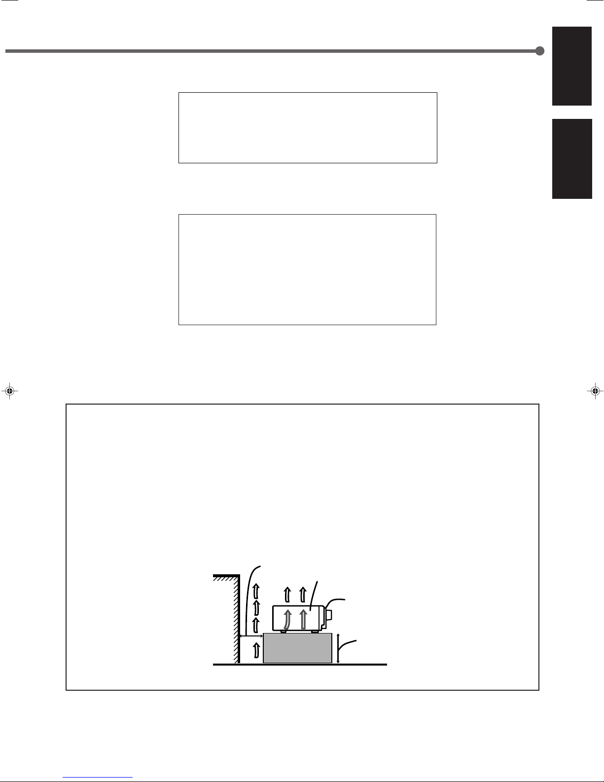
Before Installation ...................................................................... 3
Checking the Supplied Accessories ........................................... 3
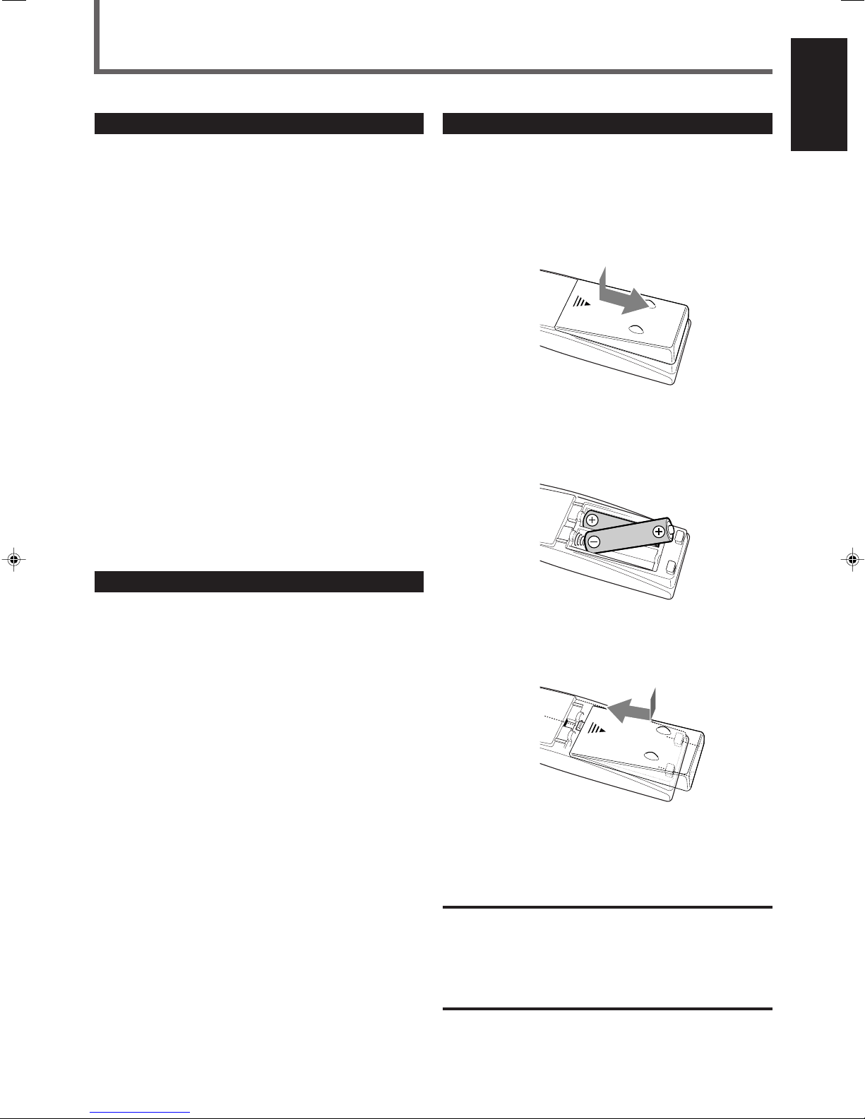
Putting Batteries in the Remote Control .................................... 3
Connecting the FM and AM Antennas ....................................... 4
Connecting the Speakers ............................................................ 5
Connecting Audio/Video Components ....................................... 6
Connecting the Power Cord ....................................................... 9
Basic Operations ....................................... 10
Turning On the Power .............................................................. 10
Selecting the Source to Play ..................................................... 10
Adjusting the Volume ............................................................... 11
Selecting the Front Speakers .................................................... 11
Listening Only with Headphones ............................................. 12
Turning Off the Sounds Temporarily—Muting........................ 12
Changing the Display Brightness ............................................. 12
Turning Off the Power with the Sleep Timer ........................... 12
Basic Settings ........................................... 14
Setting the Digital Input (DIGITAL IN) Terminals ................. 14
Selecting the Analog or Digital Input Mode ............................ 14
Setting the Video Input Terminal ............................................. 16
Setting the Speaker Information ............................................... 16
Sound Adjustments.................................... 19
Attenuating the Input Signal .................................................... 19
Adjusting the Front Speakers Output Balance ......................... 19
Adjusting the Tone ................................................................... 20
Adjusting the Subwoofer Output Level.................................... 20
Reinforcing the Bass ................................................................ 20
Tuner Operations ....................................... 21
Tuning in Stations Manually .................................................... 21
Using Preset Tuning ................................................................. 21
Selecting the FM Reception Mode ........................................... 22
Creating Realistic Sound Fields ................... 23
About Relations between Speaker Layouts and
Surround Modes ................................................................. 25
Using Dolby Pro Logic II, Dolby Digital
and DTS Digital Surround ................................................. 26
Using DAP Modes and All Channel Stereo ............................. 28
Using DVD MULTI Playback Mode ................ 30
Activating DVD MULTI Playback Mode ................................ 30
COMPU LINK Remote Control System ......... 31
AV COMPU LINK Remote Control System .... 32
Operating JVC’s Audio/Video
Components .......................................... 34
Operating Audio Components .................................................. 34
Operating Video Components .................................................. 36
Operating Other Manufacturers’Video
Equipment ............................................ 37
Troubleshooting ......................................... 40
Specifications ............................................ 41
This mark indicates that the remote control CAN
ONLY be used for the operation explained.
Remote
NOT
This mark indicates that the remote control CANNOT
be used for the operation explained. Use buttons on
the front panel.
EN01-09.RX-7520V[C]f.pm5 02.2.14, 4:31 PM1

2
English
Parts Identification
Front Panel
ADJUST
RX-7520V
AUDIO/VIDEO CONTROL RECEIVER
SETTING
MASTER VOLUME
CONTROL
DOWN UP
SURROUND MODE
PHONES
SURROUND ON/OFF
FM/AM TUNING
STANDBY
FM/AM PRESET FM MODE
MEMORY
125
48
79
p
tuio
6
3
STANDBY/ON
DVD VCR
TV SOUND
CD TAPE/CDR
SOURCE NAME
AM
DVD MULTI
FM
y
r
qwe
INPUT
ANALOG/DIGITAL
SPEAKERS ON/OFF
BASS BOOST
12
LC
S.WFR
LS RS
CH-
S
LFE
SPK
PRO LOGIC ΙΙ DSP H.PHONE
AUTOMUTING
TUNED STEREO
VOLUME
BASS BOOST
INPUT ATT
SLEEP
OPERATION
DIGITAL AUTO
ANALOG
DIGITAL
LINEAR PCM
12
R
INPUT ATT
Remote Control
FM MODE
PTY–PTY SEARCH–PTY
7
8
4
t
;
y
6
5
p
q
i
u
9
3
1
2w
o
r
e
Front Panel
1STANDBY/ON button and STANDBY lamp (10)
2FM/AM TUNING 5/∞buttons (21)
3FM/AM PRESET 5/∞buttons (21, 22)
4FM MODE button (22)
5MEMORY button (21, 22)
6Display (10)
7ADJUST button (19, 20, 27 –30)
8Remote sensor (3)
9SETTING button (14, 16 –18)
pMASTER VOLUME control (11)
qPHONES jack (12)
wSURROUND ON/OFF button (25, 27, 29)
eSURROUND MODE button (25, 27, 29)
r•INPUT ANALOG/DIGITAL button (15)
•INPUT ATT button (19)
tSPEAKERS ON/OFF 1 and 2 buttons (11, 12)
yBASS BOOST button (20)
uSOURCE NAME button (11)
iSource selecting buttons (10, 11, 14, 21, 22, 30)
DVD MULTI, DVD, VCR, TV SOUND, CD, TAPE/CDR, FM, AM
oCONTROL UP5/DOWN∞buttons (14, 16 –20, 27 –30)
Remote Control
1TV/CATV selector (36, 37)
2•10 keys for selecting preset channels (22)
•10 keys for adjusting sound (20, 27, 28, 30, 34)
•10 keys for operating audio/video components (34 –37)
3SOUND button (20, 27, 28, 30, 34)
4Operating buttons for audio/video components (34 –36, 38, 39)
5REC PAUSE button (35, 36, 38)
6Source selecting buttons (10, 11, 14, 21, 22, 30, 34 –39)
TAPE/CDR, CD, DVD, DVD MULTI, FM/AM, TV SOUND, VCR
7FM MODE button (22)
8DIMMER button (12)
9TV/VIDEO button (36, 37)
pVCR CH (channel) +/–buttons (36, 38)
qTV/CATV CH (channel) +/–buttons (36, 37)
wSTANDBY/ON buttons (10, 33, 36 –39)
AUDIO, TV/CATV, VCR, DVD
eSLEEP button (12)
rCD–DISC button (35)
tANALOG/DIGITAL button (15)
yBASS BOOST button (20)
uSURROUND ON/OFF and SURROUND MODE buttons (25, 28)
iMUTING button (12)
oVOLUME +/–button (11)
;TV VOLUME +/–buttons (36, 37)
See pages in the parentheses for details.
EN01-09.RX-7520V[C]f.pm5 02.2.14, 4:31 PM2

3
English
Getting Started
Putting Batteries in the Remote Control
Before using the remote control, put two supplied batteries first.
•When using the remote control, aim the remote control directly at
the remote sensor on the unit.
1
On the back of the remote control, remove the
battery cover.
2
Insert batteries.
•Make sure to match the polarity: (+) to (+) and (–) to (–).
3
Replace the cover.
If the range or effectiveness of the remote control decreases, replace
the batteries. Use two R6P(SUM-3)/AA(15F) type dry-cell batteries.
CAUTION:
Follow these precautions to avoid leaking or cracking cells:
•Place batteries in the remote control so they match the polarity:
(+) to (+) and (–) to (–).
•Use the correct type of batteries. Batteries that look similar may
differ in voltage.
•Always replace both batteries at the same time.
•Do not expose batteries to heat or flame.
Before Installation
General Precautions
•DO NOT insert any metal object into the unit.
•DO NOT disassemble the unit or remove screws, covers, or
cabinet.
•DO NOT expose the unit to rain or moisture.
Locations
•Install the unit in a location that is level and protected from
moisture.
•The temperature around the unit must be between –5˚C and 35˚C
(23˚F and 95˚F).
•Make sure there is good ventilation around the unit. Poor
ventilation could cause overheating and damage the unit.
Handling the unit
•DO NOT touch the power cord with wet hands.
•DO NOT pull on the power cord to unplug the cord. When
unplugging the cord, always grasp the plug so as not to damage
the cord.
•Keep the power cord away from the connecting cords and the
antenna. The power cord may cause noise or screen interference. It
is recommended to use a coaxial cable for antenna connection,
since it is well-shielded against interference.
•When a power failure occurs, or when you unplug the power cord,
the preset settings such as preset FM/AM channels and sound
adjustments may be erased in a few days.
Checking the Supplied Accessories
Check to be sure you have all of the following supplied accessories.
The number in the parentheses indicates the quantity of the pieces
supplied.
• Remote Control (1)
• Batteries (2)
• AM Loop Antenna (1)
• FM Antenna (1)
If anything is missing, contact your dealer immediately.
EN01-09.RX-7520V[C]f.pm5 02.2.14, 4:31 PM3

4
English
DIGITAL 1
(DVD)
DIGITAL 2 ( CD )
FRONT
CENTER
DVD
FM 75
COAXIAL
COMPU LINK-4
(SYNCHRO)
ANTENNA
TV SOUND
SUBWOOFER
OUT
VIDEO
VIDEOVIDEO S-VIDEOS-VIDEO
AUDIO
AUDIO
OUT
(REC)
RIGHT LEFT
LEFT
AM
LOOP
AM
EXIT
RIGHT LEFT
TAPE
/CDR
IN
(PLAY)
OUT
(REC)
VCR
IN
(PLAY)
DIGITAL IN
CENTER
SPEAKER
REAR
SPEAKERS
RIGHT LEFT
FRONT
SPEAKERS
RIGHT LEFT
CAUTION : SPEAKER IMPEDANCE
OR
AND
: 8 16
:16 32
+
–
+
–
++
2
2
2
1
1
1
––
CD
REAR
SUB
WOOFER
OUT
(REC)
VCR
IN
(PLAY)
AV
COMPU LINK-
DVD
YP
B
/C
B
P
R
/C
R
VCR
MONITOR OUT
COMPONENT VIDEO
CAUTION :
SPEAKER IMPEDANCE
816
RIGHT
MONITOR
OUT
AM
LOOP
FM 75
COAXIAL
AM
EXT
ANTENNA
FM 75
COAXIAL
FM 75
COAXIAL
123
Connecting the FM and AM Antennas
Getting Started
If AM reception is poor, connect
outdoor single vinyl-covered wire
(not supplied).
AM Loop Antenna
(supplied) Outdoor FM antenna (not supplied)
If FM reception is poor, connect outdoor
FM antenna.
Standard type
outdoor FM antenna
(not supplied)
Supplied FM
antenna
or
FM antenna (supplied)
Extend the supplied FM antenna horizontally.
Snap the tabs on the loop
into the slots of the base
to assemble the AM loop
antenna.
AM antenna connection
Connect the supplied AM loop antenna to the AM LOOP
terminals.
Turn the loop until you have the best reception.
•If the reception is poor, connect an outdoor single vinyl-
covered wire (not supplied) to the AM EXT terminal. (Keep the
AM loop antenna connected.)
FM antenna connection
Connect the supplied FM antenna to the FM 75 ΩCOAXIAL
terminal as a temporary measure.
Extend the supplied FM antenna horizontally.
•If the reception is poor, connect an outdoor FM antenna (not
supplied). Before attaching a 75 Ωcoaxial cable (with a
standard type connector), disconnect the supplied FM antenna.
Notes:
•If the AM loop antenna wire is covered with vinyl,
remove the vinyl while twisting it as shown on the
right.
•Make sure the antenna conductors do not touch any
other terminals, connecting cords and power cord.
This could cause poor reception.
EN01-09.RX-7520V[C]f.pm5 02.2.14, 4:31 PM4

5
English
Connection diagram
FRONT
SPEAKERS
RIGHT LEFT
+
1
–
RIGHT LEFT
2
+
–
FRONT
SPEAKERS
1
FRONT
SPEAKERS
2
RIGHT LEFT
1
RIGHT LEFT
1
RIGHT LEFT
1
123
Connecting speakers to the FRONT SPEAKERS 1terminals
For each speaker, connect the (+) and (–) terminals on the rear panel
to the (+) and (–) terminals marked on the speakers.
1
Cut, twist and remove the insulation at the end of
each speaker signal cable (not supplied).
2
Turn the knob counterclockwise.
3
Insert the speaker signal cable.
4
Turn the knob clockwise.
Connecting speakers to the FRONT SPEAKERS 2terminals
For each speaker, connect the (+) and (–) terminals on the rear panel
to the (+) and (–) terminals marked on the speakers.
1
Cut, twist and remove the insulation at the end of
each speaker cord.
2
Open the terminal (1), then insert the speaker
cord (2).
3
Close the terminal.
1
2
4321
“NO”for the subwoofer, “LARGE”for the front speakers,
and “SMALL”for the center and rear speakers are initial
settings. To get best possible sound, change the subwoofer and
speaker settings to fit your listening conditions.
Connecting the Speakers
Speaker layout diagram
After connecting the front, center, rear speakers and/or subwoofer,
set the speaker setting information properly to obtain the best
possible Surround effects. For details, see pages 16 to 18.
CAUTION:
Use speakers with the SPEAKER IMPEDANCE indicated by the
speaker terminals.
Connecting the front speakers
You can connect two pairs of front speakers (one pair to the FRONT
SPEAKERS 1terminals, and the other pair to the FRONT
SPEAKERS 2terminals).
About the speaker impedance
The required speaker impedance of the front speakers does differ
depending on whether both the FRONT SPEAKERS 1and FRONT
SPEAKERS 2terminals are used or only one of them is used.
CASE 1 When you connect only one pair of front speakers
Front
speaker
1
Front
speaker
1
Use front speakers with 8 Ω–16 Ωimpedance.
CASE 2 When you connect two pairs of front speakers
Front
speaker
1
Front
speaker
2
Front
speaker
2
Front
speaker
1
Use front speakers with 16 Ω–32 Ωimpedance.
Right rear
speaker
Left front
speaker Subwoofer
Center
speaker
Left rear
speaker
Right front
speaker
DVD VCR
TVSOUND/DBS
ADJUST
RX-7020VAUDIO/VIDEO CONTROL RECEIVER
SETTING
MASTERVOLUME
CONTROL
DOWN UP
CD TAPE/CDR
SOURCENAME
BASSBOOST
INPUT
ANALOG/DIGITAL
SPEAKERSON/OFF
SURROUNDMODE
PHONES
SURROUNDON/OFF
FM/AMTUNING
STANDBY
FM/AMPRESET FMMODE
MEMORY
INPUTATT
FM/AM
DIGITAL
SURROUND
DVDMULTI
PHONO
SOURCENAME
12
COMPULINK
Remote
EN01-09.RX-7520V[C]f.pm5 02.2.14, 4:31 PM5

6
English
Getting Started
Left rear
speaker
Right rear
speaker
CENTER
SPEAKER
REAR
SPEAKERS
RIGHT LEFT
+
–
Center
speaker
Connecting the rear and center speakers
Connect rear speakers to the REAR SPEAKERS terminals and a
center speaker to the CENTER SPEAKER terminals.
RIGHT LEFT
2
14
RIGHT LEFT
3
For each speaker, connect the (+) and (–) terminals on the rear panel
to the (+) and (–) terminals marked on the speakers.
1
Cut, twist and remove the insulation at the end of
each speaker signal cable (not supplied).
2
Turn the knob counterclockwise.
3
Insert the speaker signal cable.
4
Turn the knob clockwise.
Connecting the subwoofer speaker
By connecting a subwoofer, you can enhance the bass or reproduce
the original LFE signals recorded on the digital software.
Connect the input jack of a powered subwoofer to the
SUBWOOFER OUT jack on the rear panel, using a cable with RCA
pin plugs (not supplied).
•Refer also to the manual supplied for your subwoofer.
Since bass sound is non-directional, you can place a
subwoofer wherever you like. Normally place it in front of
you.
Connecting Audio/Video Components
Turn off all components before connecting.
You can connect the following audio/video components to this unit.
Refer also to the manuals supplied with your components.
*
You can connect these components using the methods described in
“Analog connections”(below) or in “Digital connections”(see page 9).
Analog connections
Audio component connections
Use the cables with RCA pin plugs (not supplied).
Connect the white plug to the audio left jack, and the red plug to the
audio right jack.
CAUTION:
If you connect a sound-enhancing device such as a graphic equalizer
between the source components and this receiver, the sound output
through this receiver may be distorted.
Audio Components Video Components
•CD player* •VCR
•Cassette deck •TV*
or CD recorder* •DVD player*
CD player
AUDIO
REAR
RIGHT LEFT
FRONT
CENTER
DVD
SUBWOOFER
OUT
SUB
WOOFER
RIGHT LEFT
Powered subwoofer
RIGHT LEFT
To audio output
AUDIO
TV SOUND
OUT
(REC)
TAPE
CDR
CD
OUT
(REC)
IN
(PLAY)
RIGHT LEFT
VCR
IN
(PLAY)
CD player
EN01-09.RX-7520V[C]f.pm5 02.2.14, 4:31 PM6

7
English
Cassette deck or CD recorder
Cassette deck
To audio outputTo audio input
AUDIO
TV SOUND
VCR
OUT
(REC)
IN
(PLAY)
TAPE
CDR
CD
OUT
(REC)
IN
(PLAY)
RIGHT LEFT
CD recorder
To audio input To audio output
Video component connections
Use the cables with RCA pin plugs (not supplied).
Connect the white plug to the audio left jack, the red plug to the
audio right jack, and the yellow plug to the video jack.
•If video components have S-video (Y/C-separation) and/or
component video (Y, PB/CB, PR/CR) terminals, connect them using
an S-video cable (not supplied) and/or component video cable (not
supplied). By using these terminals, you can get a better picture
quality in the order—Component video > S-video > Composite
video.
IMPORTANT:
This unit is equipped with the following video terminals: composite
video, S-video and component video terminals. You can use any of
these three to connect a video component.
However, remember that the video signals from one type of these
input terminals are output only through the video output
terminals of the same type.
Therefore, if a recording video component and a playing video
component are connected to the unit through the different types of
video terminals, you cannot record the picture from the playing
component onto the recording component. In addition, if the TV and a
playing video component are connected to the unit through the
different types of video terminals, you cannot view the playback
picture from the playing component on the TV.
VCR
Note:
You can connect either a cassette deck or a CD recorder to the
TAPE/CDR jacks. When connecting a CD recorder to the TAPE/CDR
jacks, change the source name, which will be shown on the display
when selected as the source. See page 11 for details.
If your audio components have a COMPU LINK jack
See also page 31 for detailed information about the connection and
the COMPU LINK remote control system.
ÅTo left/right channel audio output
ıTo left/right channel audio input
ÇTo composite video output
ÎTo S-video output
‰To S-video input
ÏTo composite video input
ÌTo component video output
Note:
See “Selecting the Video Input Terminal”on page 16 for details.
G
COMPONENT VIDEO
MONITOR OUT
VCR
DVD
YP
B
/C
B
P
R
/C
R
AUDIO
VIDEO
TV SOUND
VCR VCR
OUT
(REC) OUT
(REC)
IN
(PLAY) IN
(PLAY)
TAPE
CDR
CD
OUT
(REC)
IN
(PLAY)
MONITOR
OUT
RIGHT LEFT
DVD
S-VIDEO
VIDEO
REAR
LEFT
FRONT
CENTER
DVD
SUBWOOFER
OUT
SUB
WOOFER
RIGHT LEFT
AUDIO
RIGHT
F
E
C
D
A
B
S-VHS (or VHS) VCR
EN01-09.RX-7520V[C]f.pm5 02.2.14, 4:31 PM7

8
English
Getting Started
TV
COMPONENT VIDEO
MONITOR OUT
VCR
DVD
YP
B
/C
B
P
R
/C
R
VIDEO
VCR
OUT
(REC)
IN
(PLAY)
MONITOR
OUT
DVD
AUDIO
REAR
RIGHT LEFT
FRONT
CENTER
DVD
SUBWOOFER
OUT
SUB
WOOFER
RIGHT LEFT
S-VIDEO
VIDEO
DVD
E
C
A
D
F
G
B
DVD player
For enjoying DVD MULTI Playback Mode—
•When you connect the DVD player with its analog discrete output
(5.1 CH reproduction) jacks:
ÅTo rear left/right channel audio output
ıTo subwoofer audio output
ÇTo front left/right channel audio output
ÎTo center channel audio output
‰To composite video output
ÏTo S-video output
ÌTo component video output
ÅTo front left/right channel audio output
ıTo composite video output
ÇTo S-video output
ÎTo component video output
•When you connect the DVD player with stereo output jacks:
DVD player
TV
COMPONENT VIDEO
MONITOR OUT
VCR
DVD
YPB/CBPR/CR
AUDIO
VIDEO
TV SOUND
VCR VCR
OUT
(REC) OUT
(REC)
IN
(PLAY) IN
(PLAY)
TAPE
CDR
CD
OUT
(REC)
IN
(PLAY)
MONITOR
OUT
RIGHT LEFT
DVD
S-VIDEO
VIDEO
REAR
RIGHT LEFT
FRONT
CENTER
DVD
SUBWOOFER
OUT
SUB
WOOFER
RIGHT LEFT
AD
BC
AUDIO
ÅTo audio output
ıTo composite video input
ÇTo S-video input
ÎTo component video input
VIDEO
COMPONENT VIDEO
MONITOR OUT
VCR
DVD
YP
B
/C
B
P
R
/C
R
VCR
OUT
(REC)
IN
(PLAY)
MONITOR
OUT
DVD
AUDIO
REAR
RIGHT LEFT
FRONT
CENTER
DVD
SUBWOOFER
OUT
SUB
WOOFER
RIGHT LEFT
S-VIDEO
VIDEO
DVD
B
A
C
D
DVD player
EN01-09.RX-7520V[C]f.pm5 02.2.14, 4:31 PM8

9
English
DVD
DIGITAL 1
(DVD)
DIGITAL IN
DIGITAL 2 ( CD )
Digital connections
This receiver is equipped with two DIGITAL IN terminals—one
digital coaxial terminal and one digital optical terminal.
You can connect any digital component to one of the digital
terminals using a digital coaxial cable (not supplied).
IMPORTANT:
•When connecting the DVD player or digital TV using the digital
terminals, you also need to connect it to the video jack on the rear.
Without connecting it to the video jack, you can view no playback
picture.
•After connecting the components using the DIGITAL IN terminals,
set the following correctly if necessary:
–Set the digital input (DIGITAL IN) terminal setting correctly. For
details, see “Setting the Digital Input (DIGITAL IN) Terminals”on
page 14.
–Select the digital input mode correctly. For details, see “Selecting
the Analog or Digital Input Mode”on page 14.
Digital input terminals
CD player CD recorder
DVD player
Digital TV
Before connecting a digital
optical cable, unplug the
protective plug.
When the component has a digital coaxial
output terminal, connect it to the DIGITAL 1
(DVD) terminal with the digital coaxial cable
(not supplied).
When the component has a digital optical
output terminal, connect it to the DIGITAL 2
(CD) terminal, using the digital optical cable
(not supplied).
Notes:
•When shipped from the factory, the DIGITAL IN terminals have
been set for use with the following components:
–DIGITAL 1 (coaxial): For DVD player
–DIGITAL 2 (optical): For CD player
•When you want to operate the CD player or CD recorder using the
COMPU LINK remote control system, connect the target
component also as described in “Analog connections”(see pages 6
and 7).
•When you want to operate the DVD player using the AV COMPU
LINK remote control system, connect the DVD player also as
described in “Analog connections”(see page 8).
Connecting the Power Cord
Before plugging the receiver into an AC outlet, make sure that all
connections have been made.
Plug the power cord into an AC outlet.
Keep the power cord away from the connecting cables and the
antenna. The power cord may cause noise or screen interference. We
recommend that you use a coaxial cable to connect the antenna,
since it is well-shielded against interference.
CAUTIONS:
•Do not touch the power cord with wet hands.
•Do not pull on the power cord to unplug the cord. When unplugging
the cord, always grasp the plug so as not to damage the cord.
Digital optical cable (not supplied)
between digital optical terminals
Digital coaxial cable (not supplied)
between digital coaxial terminals
EN01-09.RX-7520V[C]f.pm5 02.2.14, 4:31 PM9

10
English
Front Panel
Turning On the Power
Press STANDBY/ON (or STANDBY/ON AUDIO on the
remote control).
The STANDBY lamp goes off. The name of the current source (or
station frequency) appears on the display.
To turn off the power (into standby mode)
Press STANDBY/ON
(or STANDBY/ON AUDIO on the remote
control) again.
The STANDBY lamp lights up.
Note:
A small amount of power is consumed in standby mode. To turn the
power off completely, unplug the AC power cord.
Basic Operations
Selecting the Source to Play
Press one of the source selecting buttons. The selected source name
appears on the display.
DVD MULTI : Select the DVD player for viewing the digital video
disc using the analog discrete output mode (5.1 ch
reproduction).
To enjoy the DVD MULTI playback, see page 30.
DVD : Select the DVD player.
VCR : Select the VCR.
TV SOUND : Select the TV sound.
CD * : Select the CD player.
TAPE/CDR * : Select the cassette deck (or the CD recorder).
FM and AM (FM/AM) *
: Select an FM or AM broadcast.
•Each time you press FM/AM on the remote
control, the band alternates between FM and AM.
Notes:
•When connecting a CD recorder (to the TAPE/CDR jacks), change
the source name that appears on the display. See “Changing the
source name”on page 11.
•When you have connected some digital source components using
the digital terminals (see page 9), you need to select the digital
input mode (see page 14).
•When you press one of the source selecting buttons on the remote
control marked above with an asterisk (
*
), the receiver
automatically turns on.
On the front panel From the remote control
DVD VCR
TV SOUND
CD TAPE/CDR
SOURCE NAME
AM
DVD MULTI
FM
AUDIO
STANDBY/ON
On the front panel From the remote control
STANDBY
STANDBY/ON
TAPE/CDR CD DVD DVD MULTI
FM/AM TV SOUND VCR
Display
ADJUST
RX-7520V
AUDIO/VIDEO CONTROL RECEIVER
SETTING
MASTER VOLUME
CONTROL
DOWN UP
SURROUND MODE
PHONES
SURROUND ON/OFF
FM/AM TUNING
STANDBY
FM/AM PRESET FM MODE
MEMORY
STANDBY/ON
DVD VCR
TV SOUND
CD TAPE/CDR
SOURCE NAME
AM
DVD MULTI
FM
BASS BOOST
INPUT
ANALOG/DIGITAL
SPEAKERS ON/OFF
INPUT ATT
12
LC
S.WFR
LS RS
CH-
S
LFE
SPK
PROLOGIC ΙΙ DSP H.PHONE
AUTOMUTING
TUNED STEREO
VOLUME
BASS BOOST
INPUT ATT
SLEEP
DIGITAL AUTO
ANALOG
DIGITAL
LINEAR PCM
12
R
Source
Selecting
Buttons
MASTER
VOLUME
SPEAKERS
ON/OFF
PHONES
jack
STANDBY/ON
STANDBY lamp
SOURCE
NAME
SLEEP
VOLUME
+/–
MUTING
Source
Selecting
Buttons
DIMMER
FM MODE
PTY–PTY SEARCH–PTY
STANDBY/ON
AUDIO
Remote Control
STANDBY/ON
STANDBY
Current source name appears
LC
S.WFR
LS RS
CH-
S
LFE
SPK
VOLUME
ANALOG 1
R
Current volume level is shown here
EN10-22.RX-7520V[C]f.pm5 02.2.14, 4:31 PM10

11
English
Adjusting the Volume
On the front panel:
To increase the volume,
turn MASTER VOLUME clockwise.
To decrease the volume,
turn it counterclockwise.
From the remote control:
To increase the volume, press VOLUME +.
To decrease the volume, press VOLUME –.
CAUTION:
Always set the volume to the minimum before starting any source. If
the volume is set at its high level, the sudden blast of sound energy
can permanently damage your hearing and/or ruin your speakers.
Note:
The volume level can be adjusted within the range of “0”(minimum) to
“50”(maximum).
Selecting the Front Speakers
When you have connected two pairs of the front speakers, you can
select which to use.
To use the speakers connected to the FRONT SPEAKERS 1
terminals, press SPEAKERS ON/OFF 1 so that the SPK 1 indicator
lights up on the display. (Make sure that the SPK 2 is not lit on the
display.)
To use the speakers connected to the FRONT SPEAKERS 2
terminals, press SPEAKERS ON/OFF 2 so that the SPK 2 indicator
lights up on the display. (Make sure that the SPK 1 is not lit on the
display.)
To use both set of the speakers, press SPEAKERS ON/OFF 1 and
2 so that the SPK 1 and SPK 2 indicators light up on the display.
To use neither set of the speakers, press SPEAKERS ON/OFF
1 and 2 so that the SPK 1 and SPK 2 indicators disappear from the
display.
Notes:
•If you select any of the Surround modes while using both the speakers
connected to the FRONT SPEAKERS
1
and
2
terminals, the
speakers connected to the FRONT SPEAKERS
2
terminals are
deactivated.
•While the Surround mode is in use, you can only select either the
speakers connected to the FRONT SPEAKERS
1
or
2
terminals.
•If you select DVD MULTI as the source while using both the speakers
connected to the FRONT SPEAKERS
1
and
2
terminals, the
speakers connected to the FRONT SPEAKERS
2
terminals are
deactivated.
•When selecting “DVD MULTI”as the source, you can only select
either the speakers connected to the FRONT SPEAKERS
1
or
2
terminals.
Remote
NOT
MASTER VOLUME
VOLUME
TAPE/CDR
SOURCE NAME
TAPE/CDR
SOURCE NAME
From the remote control
On the front panel
DVD VCR
TV SOUND
CD TAPE/CDR
SOURCE NAME
AM
DVD MULTI
FM
TAPE/CDR CD DVD DVD MULTI
FM/AM TV SOUND VCR
Changing the source name
When you connect a CD recorder to the
TAPE/CDR jacks on the rear panel, change the
source name shown on the display.
1
Press TAPE/CDR (SOURCE NAME).
•Make sure “TAPE”appears on the display.
2
Press and hold SOURCE NAME (TAPE/CDR)
until “ASSIGN CDR”appears on the display.
To change the source name from “CDR”to “TAPE,”repeat the
same procedure above (in step
1
, make sure “CDR”appears on the
display).
Note:
Without changing the source name, you can still use the connected
component. However, there may be some inconvenience:
–“TAPE”will appear on the display when you select the CD
recorder.
–You cannot use the digital input (see page 14) for the CD recorder.
–You cannot use the COMPU LINK remote control system (see page
31) to operate the CD recorder.
Selecting different sources for picture and sound
You can watch picture from a video component while listening to
sound from another component.
Press one of the audio source selecting buttons—
CD, TAPE/CDR, FM, AM (or FM/AM on the remote control),
while watching the picture from a video component such as the
VCR, or DVD player, etc.
Notes:
•Once you have selected a video source, pictures of the selected
source are sent to the TV until you select another video source.
•This function can use only when selecting the S-video or composite
video input terminal.
SPEAKERS ON/OFF
12
Remote
NOT
EN10-22.RX-7520V[C]f.pm5 02.2.14, 4:31 PM11

12
English
Basic Operations
Changing the Display Brightness
You can dim the display.
Press DIMMER on the remote control.
•Each time you press the button, the display dims and
brightens alternately.
Turning Off the Power
with the Sleep Timer
You can fall asleep while listening to music—Sleep Timer.
Press SLEEP on the remote control repeatedly.
•The SLEEP indicator lights up on the display and the
shut-off time changes in 10 minutes intervals.
When the shut-off time comes
The receiver turns off automatically.
To check or change the remaining time until the shut-off time
Press SLEEP once.
The remaining time (in minutes) until the shut-off time appears.
•To change the shut-off time, press SLEEP repeatedly until the
preferred remaining time appears on the display.
To cancel the Sleep Timer
Press SLEEP repeatedly until “SLEEP 0 MIN”appears on the
display. (The SLEEP indicator goes off.)
•Turning off the power also cancels the Sleep Timer.
2010 30 40 50 60
70
8090
(Canceled)
0
LC
S.WFR
LS RS
CH-
S
LFE
SPK SLEEP
ANALOG 1
R
Listening Only with Headphones
You must turn off both pairs of speakers when you listen with
headphones.
1
Connect a pair of headphones to the PHONES jack on the front
panel.
2
Press SPEAKERS ON/OFF 1 and SPEAKERS ON/OFF 2 so
that neither the SPK 1 nor SPK 2 indicator appears on the
display.
•“HEADPHONE”appears and H. PHONE indicator lights up
on the display.
This cancels the Surround modes currently selected and activates
the HEADPHONE mode (see below).
HEADPHONE mode
When using the headphones, the following signals are output
regardless of your speaker setting:
—For 2 channel sources, the front left and right channel signals
are output directly from the headphones.
—For multichannel sources, the front left and right, center, and
rear channel signals are down-mixed and then output from the
headphones.
You can enjoy multichannel sound sources using the
headphones.
Notes:
•While in the HEADPHONE mode, you cannot use any Surround
modes (see page 23).
•Activating the speakers cancels the HEADPHONE mode and turns
on the Surround modes previously selected.
CAUTION:
Be sure to turn down the volume:
•Before connecting or putting on headphones, as high volume can
damage both the headphones and your hearing.
•Before turning on speakers again, as high volume may output from
the speakers.
Turning Off the Sounds
Temporarily—Muting
You can turn off the volume temporarily.
Press MUTING on the remote control to mute
the sound through all speakers and headphones
connected.
•“MUTING”appears on the display and the volume turns
off (the volume level indicator goes off).
To restore the sound, press MUTING again.
•Turning MASTER VOLUME on the front panel or pressing
VOLUME +/–on the remote control also restores the sound.
LC
S.WFR
LS RS
CH-
S
LFE
SPK
ANALOG 1
R
DIMMER
SLEEP
MUTING
L
H.PHONE
ANALOG
R
EN10-22.RX-7520V[C]f.pm5 02.2.14, 4:31 PM12

13
English
S.WFR
LS RSS
LFE
RCL
LC
S.WFR
LS RS
CH-
S
LFE
SPK
PRO LOGIC ΙΙ
DIGITAL AUTO
ANALOG
DIGITAL
LINEAR PCM
12
R
S.WFR
LS RSS
LFE
RCL
Signal indicators Speaker indicators
Basic adjustment auto memory
This receiver memorizes sound settings for each source when—:
•turning off the power,
•changing the source, and
•assigning the source name.
When you change the source, the memorized settings for the
newly selected source are automatically recalled.
The following can be stored for each source:
•Input attenuator mode (see page 19)
•Balance (see page 19)
•Tone adjustment (see page 20)
•Subwoofer output level (see page 20)
•Surround mode selection (see pages 26 –29)
•Bass boost (see page 20)
Notes:
•You cannot assign and store different settings for digital input
mode and analog input mode.
•If the source is FM or AM, you can assign a different setting for
each band.
For recording
You can record any source through the receiver to —:
•the cassette deck (or CD recorder) connected to the
TAPE/CDR jacks, and
•the VCR connected to the VCR jacks at the same time.
While recording, you can listen to the selected sound source at
whatever sound level you like without affecting the sound levels
of the recording.
Note:
The output volume level, bass boost (see page 20), tone
adjustment (see page 20), and Surround modes (see page 23)
cannot affect the recording.
Signal and speaker indicators on the display
The following signal indicators light up—:
L:•When digital input is selected: Lights up when the left
channel signal comes in.
•When analog input is selected: Always lights up.
R:•When digital input is selected: Lights up when the right
channel signal comes in.
•When analog input is selected: Always lights up.
C:When the center channel signal comes in.
LS : When the left rear channel signal comes in.
RS : When the right rear channel signal comes in.
S:When the monaural rear channel signal or 2 ch Dolby
Surround encoded signal comes in.
LFE: When the LFE channel signal comes in.
The speaker indicators light up when—:
•The corresponding speaker is activated, and
•The corresponding speaker is required for the current playback.
Notes:
•When you select “DVD MULTI,”all the signal indicators except
“S”light up.
•When “SUBWOOFER”is set to “YES”(see page 16),
S.WFR
lights up.
EN10-22.RX-7520V[C]f.pm5 02.2.14, 4:31 PM13

14
English
Setting the Digital Input
[DIGITAL IN] Terminals
When you use the digital input terminals, register what components
are connected to which terminals (DIGITAL IN 1/2) so that the correct
source name will appear when you select the digital source.
Before you start, remember....
There is a time limit in doing the following steps. If the setting is
canceled before you finish, start from step
1
again.
1
Press SETTING repeatedly until
“DIGITAL IN”appears on the display.
Then the display changes to show the current setting.
* “1DVD 2CD”is the initial setting. If you have already
changed the setting, another combination will be shown.
2
Press CONTROL UP 5/DOWN ∞to
select the appropriate digital terminal
setting.
•Each time you press the button, the display
changes as follows:
1 DVD 2 CD j1 DVD 2 TV j1 DVD 2 CDR j
1 CD 2 DVDj1 CD 2 TV j1 CD 2 CDR j
1 TV 2 DVDj1 TV 2 CD j1 TV 2 CDR j
1 CDR 2 DVDj1 CDR 2 CD j1 CDR 2 TV j
(back to the beginning)
Note:
When shipped from the factory, the DIGITAL IN terminals have been
set for use with the following components:
–DIGITAL 1 (coaxial): For DVD player
–DIGITAL 2 (optical): For CD player
Basic Settings
Front Panel Remote Control
FM MODE
PTY–PTY SEARCH–PTY
Remote
NOT
Source
Selecting
Buttons
T SETTING
On the front panel From the remote control
TAPE/CDR CD DVD DVD MULTI
FM/AM TV SOUND VCR
DVD VCR
TV SOUND
CD TAPE/CDR
SOURCE NAME
AM
DVD MULTI
FM
Display SETTING
Source
Selecting
Buttons
INPUT ANALOG/
DIGITAL
ANALOG
/DIGITAL
ADJUST
RX-7520V
AUDIO/VIDEO CONTROL RECEIVER
SETTING
MASTER VOLUME
CONTROL
DOWN UP
SURROUND MODE
PHONES
SURROUND ON/OFF
FM/AM TUNING
STANDBY
FM/AM PRESET FM MODE
MEMORY
STANDBY/ON
DVD VCR
TV SOUND
CD TAPE/CDR
SOURCE NAME
AM
DVD MULTI
FM
BASS BOOST
INPUT
ANALOG/DIGITAL
SPEAKERS ON/OFF
INPUT ATT
12
LC
S.WFR
LS RS
CH-
S
LFE
SPK
PROLOGIC ΙΙ DSP H.PHONE
AUTOMUTING
TUNED STEREO
VOLUME
BASS BOOST
INPUT ATT
SLEEP
DIGITAL AUTO
ANALOG
DIGITAL
LINEAR PCM
12
R
CONTROL
UP 5/DOWN ∞
CONTROL
DOWN UP
DIGITAL 1 terminal setting
S.WFR
LS RS
CH-
S
LFE
DIGITAL 2 terminal setting
Selecting the Analog or Digital Input
Mode
When you have connected digital source components using both the
analog connections (see page 6) and the digital connections (see
page 9) methods, you need to select the input mode correctly.
Before you start, remember....
There is a time limit in doing the following steps. If the setting is
canceled before you finish, start from step
1
again.
1
Press one of the source selecting buttons—DVD,
TV SOUND , CD, or TAPE/CDR*—for which
you want to change the input mode.
Note:
*
Among the sources listed above, you can select the digital input
only for the sources which you have selected the digital input
terminals for. (See “Setting the Digital Input (DIGITAL IN)
Terminals”on the left column.)
EN10-22.RX-7520V[C]f.pm5 02.2.14, 4:32 PM14

15
English
INPUT
INPUT ATT
ANALOG / DIGITAL
On the front panel From the remote control
2
Press INPUT ANALOG/DIGITAL
(or ANALOG/DIGITAL on the remote control)
to select the digital input mode.
•Each time you press the button, the input mode alternates
between the analog input (“ANALOG”) and the digital input
(“DIGITAL AUTO”).
DIGITAL AUTO : Select this for the digital input mode. The
receiver automatically detects the
incoming signal format. (The DIGITAL
AUTO indicator lights up on the display,
then the digital signal indicator for the
detected signals lights up.)
ANALOG : Select this for the analog input mode.
(Initial setting when shipped from the
factory.)
If the following symptoms occur while playing Dolby Digital
or DTS Digital Surround software with “DIGITAL AUTO”
selected, follow the procedure below:
•Sound does not come out at the beginning of playback.
•Noise comes out while searching or skipping chapters or
tracks.
1
Press INPUT ANALOG/DIGITAL (or
ANALOG/DIGITAL on the remote control).
2
Press CONTROL UP 5/DOWN ∞to
select “DOLBY DIGITAL”or “DTS
SURROUND”while “DIGITAL
AUTO”still remains on the display.
•Each time you press the button, the digital input mode changes
as follows:
•To play back software encoded with Dolby Digital, select
“DOLBY DIGITAL.”
•To play back software encoded with DTS Digital Surround,
select “DTS SURROUND.”
Note:
When you turn off the power or select another source, “DOLBY
DIGITAL”and “DTS SURROUND”are canceled and the digital input
mode is automatically reset to “DIGITAL AUTO.”
The following are the analog/digital signal indicators on the display
to indicate what type of the signal comes into the receiver.
ANALOG : Lights when the analog input is selected.
LINEAR PCM : Lights when Linear PCM signals come in.
DIGITAL :•Lights when Dolby Digital signals come in.
•Flashes when “DOLBY DIGITAL”is
selected for software not encoded with Dolby
Digital signals.
:•Lights when DTS signals come in.
•Flashes when “DTS SURROUND”is
selected for software not encoded with DTS
signals.
Note:
When “DIGITAL AUTO”cannot recognize the incoming signals, no
digital signal indicators light up on the display.
LC
S.WFR
LS RS
CH-
S
LFE
SPK
DIGITAL AUTO
DIGITAL
R
DIGITAL AUTO DTS SURROUND
DOLBY DIGITAL
When “DOLBY DIGITAL”or “DTS SURROUND”
is selected, “DIGITAL AUTO”goes off.
Remote
NOT
INPUT
INPUT ATT
ANALOG / DIGITAL
On the front panel From the remote control
ANALOG
/DIGITAL
ANALOG
/DIGITAL
EN10-22.RX-7520V[C]f.pm5 02.2.14, 4:32 PM15

16
English
Selecting the Video Input
Terminal
This receiver is equipped with the component video input terminals
for the DVD player which give you higher picture quality. When you
use the component video input terminals for the DVD player, change
the video input terminal setting.
Before you start, remember....
There is a time limit in doing the following steps. If the setting is
canceled before you finish, start from step
1
again.
1
Press SETTING repeatedly until
“VIDEO IN DVD ”or “VIDEO IN
VCR ”appears on the display.
•Select “VIDEO IN DVD”to select the video input terminal for
the DVD player and “VIDEO IN VCR”for the VCR.
After 2 seconds, the display changes to show the current setting.
2
Press CONTROL UP 5/DOWN ∞
to select the appropriate type of
the video input terminal.
•Each time you press the button, the display
changes as follows:
COMPONENT : Select this when you connect the DVD
player or VCR to the component video
input terminals.
S/C : Select this when you connect the DVD player
or VCR to the S-video or composite video
input terminal.
Note:
Without changing the video input terminal setting, you can see the
picture through the video input terminals, but cannot use the AV
COMPU LINK remote control system correctly (see page 32).
Basic Settings
“NO”for the subwoofer, “LARGE”for the front speakers,
and “SMALL”for the center and rear speakers are initial
settings. To get best possible sound, change the subwoofer
and speaker settings to fit your listening conditions.
Setting the Speaker Information
To obtain the best possible sound or effect from Surround modes
(see pages 26 to 29), register the following speakers and subwoofer
information after all connections are completed.
The following are items you can set:
•Subwoofer information—SUBWOOFER
•Speaker size—FRNT SP, CNTR SP, REAR SP
•Speaker distance—UNIT, FRNT DIS, CNTR DIS, REAR DIS
•Crossover frequency—CROSS
•Low frequency effect attenuator—LFE ATT
•Dynamic range compression—D. COMP
Before you start, remember....
There is a time limit in doing the following steps. If the setting is
canceled before you finish, start from step
1
again.
Subwoofer information
Register whether you have connected a subwoofer or not.
1
Press SETTING repeatedly until
“SUBWOOFER”(with the current
setting)* appears on the display.
*“NO”is the initial setting. If you have already changed the
setting, “YES”will be shown.
2
Press CONTROL UP 5/DOWN ∞to
register whether you have connected a
subwoofer or not.
•Each time you press the button, the subwoofer
setting alternates between “YES”and “NO.”
YES : Select this when you have connected a subwoofer.
You can adjust the subwoofer output level
(see page 20).
NO : Select this when you have not connected or have
disconnected a subwoofer.
ST SETTING
CONTROL
DOWN UP
COMPONENT
(Component)
S/C
(S-video/Composite)
LC
CH-
SPK
DIGITAL AUTO
LINEAR PCM
1
R
Remote
NOT
LC
S.WFR
CH-
LFE
SPK
DIGITAL AUTO
LINEAR PCM
1
R
ST SETTING
CONTROL
DOWN UP
Remote
NOT
EN10-22.RX-7520V[C]f.pm5 02.2.14, 4:32 PM16

17
English
Speaker size
Register the sizes of all the connected speakers.
•When you change your speakers, register the information about
the speakers again.
1
Press SETTING repeatedly until “FRNT
SP (Front Speaker),”“CNTR SP (Center
Speaker)”or “REAR SP (Rear Speaker)”
(with the current setting)* appears on the display.
*“LARGE”is the initial setting for the front speakers and
“SMALL”is for the center and rear speakers. If you have
already changed the setting, another size will be shown.
2
Press CONTROL UP 5/DOWN ∞to
select the appropriate item about the
speaker selected in the above step.
•Each time you press the button, the display
changes as follows:
LARGE : Select this when the speaker size is relatively large.
(See “Notes”below.)
SMALL : Select this when the speaker size is relatively small.
(See “Notes”below.)
NONE : Select this when you have not connected a speaker.
(Not selectable for the front speakers)
3
Repeat steps
1
and
2
to select the appropriate
items for other speakers.
Notes:
•Keep the following comment in mind as reference when adjusting.
–If the size of the cone speaker unit built in your speaker is greater
than 12 cm (4
3
/
4
inches), select “LARGE,”and if it is smaller than
12 cm (4
3
/
4
inches), select “SMALL.”
•If you have selected “NO”for the subwoofer setting, you can only
select “LARGE”for the front speaker setting.
•If you have selected “SMALL”for the front speaker setting, you
cannot select “LARGE”for the center and rear speaker settings.
Speaker distance
Register the unit you use, then the speaker distance from your
listening point.
•If you have set the unit before, start from step
3
.
•Speaker distance is not valid for the DVD MULTI playback mode.
T SETTING
3.0 m
(10 feet)
Left front
speaker Right front
speaker
Right rear
speaker
Left rear
speaker
Center speaker
2.7 m
(9 feet)
2.4 m
(8 feet)
2.1 m
(7 feet)
Example: In this case,
set “FRNT DIS”to “3.0m”or “10FT,”
set “CNTR DIS”to “2.7m”or “9FT,”and
set “REAR DIS”to “2.4m”or “8FT.”
Note:
If you have selected “NONE”for the center and rear speakers setting,
you cannot set the speaker distance for the center and rear speakers.
LC
S.WFR
LS RS
CH-
S
LFE
SPK
DIGITAL AUTO
LINEAR PCM
1
R
LARGE SMALL
NONE
CONTROL
DOWN UP
T SETTING
1
Press SETTING repeatedly until “UNIT”
(with the current setting)* appears on the
display.
*“METER”is the initial setting. If you have already changed
the setting, “FEET”will be shown.
2
Press CONTROL UP 5/DOWN ∞to
select the unit.
•Each time you press the button, the setting
alternates between “METER”and “FEET.”
METER : Speaker distance is shown in meters.
FEET : Speaker distance is shown in feet.
3
Press SETTING repeatedly until “FRNT
DIS (Front distance),”“CNTR DIS
(Center distance)”or “REAR DIS (Rear
distance)”(with the current setting)*
appears on the display.
•The display shows the current setting in the unit selected in
step
2
.
*“3.0m”is the initial setting for meter and “10FT”is for feet. If
you have already changed the setting, another value will be
shown.
4
Press CONTROL UP 5/DOWN ∞to
select the appropriate speaker distance.
•If you select “METER”in step
2
, the value is
changed from “0.3m”to “9.0m”by 0.3 m step.
•If you select “FEET”in step
2
, the value is
changed from “1FT”to “30FT”by 1 foot step.
CONTROL
DOWN UP
CONTROL
DOWN UP
ST SETTING
LC
S.WFR
LS RS
CH-
S
LFE
SPK
DIGITAL AUTO
LINEAR PCM
1
R
EN10-22.RX-7520V[C]f.pm5 02.2.14, 4:32 PM17
Other manuals for RX-7520VBK
1
Table of contents
Other JVC Stereo Receiver manuals