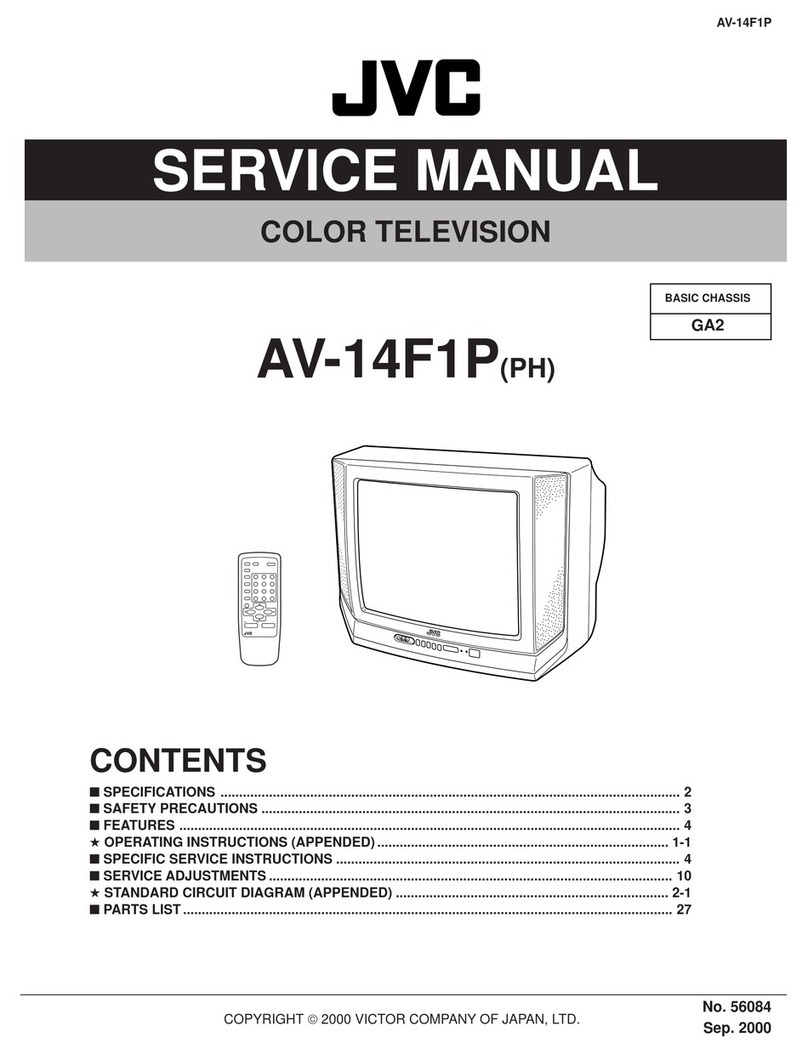
JVC AV-28BD5EKI User manual

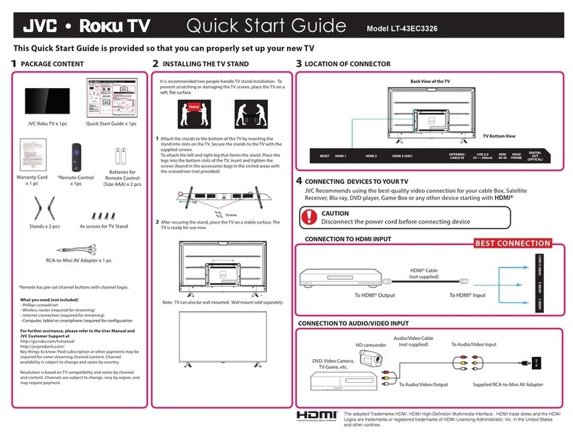
No.51709
Jun. 2000
A
V-28BD5EKI AV-28BD5EP AV-28BD5EE
A
V-28BD5EKIS AV-28BD5EPS AV-28BD5EES
1COPYRIGHT © 2000 VICTOR COMPANY OF JAPAN, LTD.
AV-28BD5EKI / AV-28BD5EP / AV-28BD5EE
AV-28BD5EKIS / AV-28BD5EPS / AV-28BD5EES
CONTENTS
SPECIFICATIONS ・・・・・・・・・・・・・・・・・・・・・・・・・・・・・・・・
・・・・・・・・・・・・・・・・・・・・・・・・・・・・・・・・・・・・・・・・・・・・・・・・・・・・・・・・・・・・・・・・
・・・・・・・・・・・・・・・・・・・・・・・・・・・・・・・・ ・・・・・・・・・・・・・・・・・・・・・・・・・・・・
・・・・・・・・・・・・・・・・・・・・・・・・・・・・・・・・・・・・・・・・・・・・・・・・・・・・・・・・
・・・・・・・・・・・・・・・・・・・・・・・・・・・・ 1-2
SAFETY PRECAUTIONS ・・・・・・・・・・・・・・・・・・・・・・・・・・・・・・・・
・・・・・・・・・・・・・・・・・・・・・・・・・・・・・・・・・・・・・・・・・・・・・・・・・・・・・・・・・・・・・・・・
・・・・・・・・・・・・・・・・・・・・・・・・・・・・・・・・ ・・・・・・・・・・・・・・・・・・・・・・
・・・・・・・・・・・・・・・・・・・・・・・・・・・・・・・・・・・・・・・・・・・・
・・・・・・・・・・・・・・・・・・・・・・ 1-5
FUNCTIONS ・・・・・・・・・・・・・・・・・・・・・・・・・・・・・・・・
・・・・・・・・・・・・・・・・・・・・・・・・・・・・・・・・・・・・・・・・・・・・・・・・・・・・・・・・・・・・・・・・
・・・・・・・・・・・・・・・・・・・・・・・・・・・・・・・・ ・・・・・・・・・・・・・・・・・・・・・・・・・・・・・・・・
・・・・・・・・・・・・・・・・・・・・・・・・・・・・・・・・・・・・・・・・・・・・・・・・・・・・・・・・・・・・・・・・
・・・・・・・・・・・・・・・・・・・・・・・・・・・・・・・・ ・
・・
・1-6
SPECIFIC SERVICE INSTRUCTIONS ・・・・・・・・・・・・・・・・・・・・・・・・・・・・・・・・
・・・・・・・・・・・・・・・・・・・・・・・・・・・・・・・・・・・・・・・・・・・・・・・・・・・・・・・・・・・・・・・・
・・・・・・・・・・・・・・・・・・・・・・・・・・・・・・・・ ・・・・・・・・・・・・
・・・・・・・・・・・・・・・・・・・・・・・・
・・・・・・・・・・・・ 1-8
SERVICE ADJUSTMENTS ・・・・・・・・・・・・・・・・・・・・・・・・・・・・・・・・
・・・・・・・・・・・・・・・・・・・・・・・・・・・・・・・・・・・・・・・・・・・・・・・・・・・・・・・・・・・・・・・・
・・・・・・・・・・・・・・・・・・・・・・・・・・・・・・・・ ・・・・・・・・・・・・・・・・・・・・・
・・・・・・・・・・・・・・・・・・・・・・・・・・・・・・・・・・・・・・・・・・
・・・・・・・・・・・・・・・・・・・・・ 1-9
★
STANDARD CIRCUIT DIAGRAM (APPENDIX) ・・・・・・・・・・・・・・・・・・・・・・・・・・・・・・・・
・・・・・・・・・・・・・・・・・・・・・・・・・・・・・・・・・・・・・・・・・・・・・・・・・・・・・・・・・・・・・・・・
・・・・・・・・・・・・・・・・・・・・・・・・・・・・・・・・ ・・・・・
・・・・・・・・・・
・・・・・ 2-1
PARTS LIST ・・・・・・・・・・・・・・・・・・・・・・・・・・・・・・・・
・・・・・・・・・・・・・・・・・・・・・・・・・・・・・・・・・・・・・・・・・・・・・・・・・・・・・・・・・・・・・・・・
・・・・・・・・・・・・・・・・・・・・・・・・・・・・・・・・ ・・・・・・・・・・・・・・・・・・・・・・・・・・・・・・・・
・・・・・・・・・・・・・・・・・・・・・・・・・・・・・・・・・・・・・・・・・・・・・・・・・・・・・・・・・・・・・・・・
・・・・・・・・・・・・・・・・・・・・・・・・・・・・・・・・ 1-15
SERVICE MANUAL
COLOUR TELEVISION
www.freeservicemanuals.info
17/3/2013
www.nostatatech.nl
World of free manuals

No.51709
A
V-28BD5EKI AV-28BD5EP AV-28BD5EE
A
V-28BD5EKIS AV-28BD5EPS AV-28BD5EES
1-2
SPECIFICATIONS
Item Content
TV RF SYSTEM B/G, I, D/K & L/L’
COLOUR STANDARD PAL / SECAM / NTSC (AV only)
POWER INPUT AC 230V, 50Hz
POWER CONSUMPTION 75W / 3W (STBY)
TELETEXT SYSTEM FLOF (Fastext) / TOP / WST (standard system)
SOUND OUTPUT / SPEAKER 7W / 8Ω(
×2)
PICTURE TUBE SIZE VISIBLE AREA 66cm (measured diagonally)
ANTENNA INPUT 75ΩUnbalanced
FRONT: RCA JACK (VIDEO / AUDIO)
INPUT / OUTPUT REAR : 21-PIN EURO CONNECTOR (SCART)×2
(VIDEO / AUDIO / RGB / S. VHS)
INTERMEDIATE FREQUENCIES PIF : 38.9MHz (B/G, D/K, I, L) , 33.9MHz (L’)
SIF : 33.4MHz (PAL / SECAM – B/G)
32.9MHz (PAL / SECAM – I / I)
32.4MHz (PAL / SECAM – D/K, SECAM – L)
40.4MHz (SECAM – L’)
SOUND SUBCARRIER : 5.5MHz (PAL / SECAM – B/G)
6.0MHz (PAL / SECAM – I / I)
6.5MHz (PAL / SECAM – D/K, SECAM – L)
6.5MHz (SECAM – L’)
COLOUR SUBCARRIER : 4.43MHz (PAL)
4.250MHz, 4.406MHz (SECAM)
REMOTE CONTROL RM-C71 [ Batt, AAA (R03) ] (EP, EPS, EE, EES)
RM-C72 [ Batt, AAA (R03) ] (EKI, EKIS)
DIMENSIONS (W×
××
×H×
××
×D) 760mm×589mm×475mm
MASS 32kg
Design & specifications are subject to change without notice.
COMMON INPUT
www.freeservicemanuals.info
17/3/2013
www.nostatatech.nl
World of free manuals

No.51709
A
V-28BD5EKI AV-28BD5EP AV-28BD5EE
A
V-28BD5EKIS AV-28BD5EPS AV-28BD5EES
1-3
■
21-pin Euro connector (SCART socket)
21Pin EURO-SCART 1:
Pin
No. Signal Designation Matching Value
1 Audio Output Right 0.5V(rms), Imp<1kΩ(RF 54% MOD)
2 Audio Input Right 0.5V(rms), Imp>10kΩ
3Audio OutputLeft 0.5V(rms), Imp<1kΩ(RF 54% MOD)
4AudioEarth
5BlueEarth
6 Audio Input Left 0.5V(rms), Imp>10kΩ
7BlueInput 0.7V(p-p) ±0.1V, Imp75Ω
8 Slow Switching TV : 0-2V, AV 16/9 : 4.5-7V, AV 4/3 : 9.5-12V, Imp>10kΩ
9 Green Earth
10 NC
11 Green Input 0.7V(p-p) ±0.1V, Imp 75Ω
12 NC
13 Red Earth
14 Blanking Earth
15 Red Input 0.7V(p-p) ±0.1V, Imp 75Ω
16 Fast Switching 0-0.4V : Logic “0”, 1-3V : Logic “1”, Imp75Ω
17 Video Out Earth
18 Video In Earth
19 Video Output 1V(p-p) ±3dB, Imp75Ω
20 Video Input 1V(p-p) ±3dB, Imp75Ω
21 Common Earth
[Pin assignment]
www.freeservicemanuals.info
17/3/2013
www.nostatatech.nl
World of free manuals

No.51709
A
V-28BD5EKI AV-28BD5EP AV-28BD5EE
A
V-28BD5EKIS AV-28BD5EPS AV-28BD5EES
1-4
21Pin EURO-SCART 2 :
Pin
No. Signal Designation Matching Value
1NC
2Audio IntputRight 0.5V(rms), Imp<10kΩ
3NC
4AudioEarth
5Earth
6 Audio Input Left 0.5V(rms), Imp>10kΩ
7NC
8NC
9NC
10 NC
11 NC
12 NC
13 Earth
14 Earth
15 Chroma Input ±3dB for a luminance signal of 1V(p-p)
16 NC
17 Earth
18 Video In Earth
19 NC
20 Video Input, Y In. 1V(p-p) ±3dB, Imp75Ω
21 Common Earth
[
Pin assignment]
www.freeservicemanuals.info
17/3/2013
www.nostatatech.nl
World of free manuals

No.51709
A
V-28BD5EKI AV-28BD5EP AV-28BD5EE
A
V-28BD5EKIS AV-28BD5EPS AV-28BD5EES
1-5
SAFETY PRECAUTIONS
1. The design of this product contains special hardware, many circuits and components specially for safety purposes. For continued protection,
no changes should be made to the original design unless authorized in writing by the manufacturer. Replacement parts must be identical to
those used in the original circuits. Service should be performed by qualified personnel only.
2. Alterations of the design or circuitry of the products should not be made. Any design alterations or additions will void the manufacturer's
warranty and will further relieve the manufacturer of responsibility for personal injury or property damage resulting therefrom.
3. Many electrical and mechanical parts in the products have special safety-related characteristics. These characteristics are often not evident
from visual inspection nor can the protection afforded by them necessarily be obtained by using replacement components rated for higher
voltage, wattage, etc. Replacement parts which have these special safety characteristics are identified in the parts list of Service manual.
Electrical components having such features are identified by shading on the schematics and by ( ) on the parts list in Service
manual. The use of a substitute replacement which does not have the same safety characteristics as the recommended replacement part
shown in the parts list of Service manual may cause shock, fire, or other hazards.
4. Don't short between the LIVE side ground and ISOLATED (NEUTRAL) side ground or EARTH side ground when repairing.
Some model's power circuit is partly different in the GND. The difference of the GND is shown by the LIVE : () side GND, the
ISOLATED(NEUTRAL) : () side GND and EARTH : () side GND. Don't short between the LIVE side GND and ISOLATED(NEUTRAL)
side GND or EARTH side GND and never measure with a measuring apparatus (oscilloscope etc.) the LIVE side GND and
ISOLATED(NEUTRAL) side GND or EARTH side GND at the same time.
If above note will not be kept, a fuse or any parts will be broken.
5. If any repair has been made to the chassis, it is recommended that the +B setting should be checked or adjusted (See +B ADJUSTMENT).
6. The high voltage applied to the picture tube must conform with that specified in Service manual. Excessive high voltage can cause an
increase in X-Ray emission, arcing and possible component damage, therefore operation under excessive high voltage conditions should
be kept to a minimum, or should be prevented. If severe arcing occurs, remove the AC power immediately and determine the cause by
visual inspection (incorrect installation, cracked or melted high voltage harness, poor soldering, etc.). To maintain the proper minimum level
of soft X-Ray emission, components in the high voltage circuitry including the picture tube must be the exact replacements or alternatives
approved by the manufacturer of the complete product.
7. Do not check high voltage by drawing an arc. Use a high voltage meter or a high voltage probe with a VTVM. Discharge the picture tube
before attempting meter connection, by connecting a clip lead to the ground frame and connecting the other end of the lead through a 10k:
2W resistor to the anode button.
8. When service is required, observe the original lead dress. Extra precaution should be given to assure correct lead dress in the high voltage
circuit area. Where a short circuit has occurred, those components that indicate evidence of overheating should be replaced. Always use
the manufacturer's replacement components.
www.freeservicemanuals.info
17/3/2013
www.nostatatech.nl
World of free manuals

No. 51709
A
V-28BD5EKI AV-28BD5EP AV-28BD5EE
A
V-28BD5EKIS AV-28BD5EPS AV-28BD5EES
1-6
FUNCTIONS
LOCAL CONTROL
FRONT
BACK
MAIN POWER
BUTTON
V
IDEO
INPUT
AUDIO
INPUT
HEAD
PHONE
STAND-BY
INDICATOR
REMOTE
SENSOR
A
V BUTTON
V
OLUME
DOWN/UP
BUTTONS
PR (PROGRAM)
DOWN/UP
BUTTONS
AERIAL TERMINAL
SCART JACK 1(AV1)
SCART JACK 2(AV2)
www.freeservicemanuals.info
17/3/2013
www.nostatatech.nl
World of free manuals

No. 51709
A
V-28BD5EKI AV-28BD5EP AV-28BD5EE
A
V-28BD5EKIS AV-28BD5EPS AV-28BD5EES
1-7
REMOTE CONTROL
TV mode
1. POWER
2. NUMBER 0-9 / NUMBER
3. P.MODE / OK
4. AV
5. UP
6. RIGHT
7. MENU
8. DOWN
9. LEFT
10. MUTING
11. RECALL
12. SLEEP
13. Not used
14. MOVE
15. SKIP
16. TV / TEXT
17. DELETE
18. MODE
19. VCR / / DVD switch
20. VCR / DVD Control buttons
TELETEXT mode
1. POWER
2. NUMBER 0-9
3. INDEX
4. Not used
5. UP
6. SUBPAGE
7. MENU
8. DOWN
9. HOLD
10. MUTING
11. REVEAL
12. SIZE
13. CANCEL
14. GREEN
15. RED
16. TV / TEXT
17. YELLOW
18. CYAN
19. VCR / / DVD switch
20. Not used
www.freeservicemanuals.info
17/3/2013
www.nostatatech.nl
World of free manuals

No.51709
A
V-28BD5EKI AV-28BD5EP AV-28BD5EE
A
V-28BD5EKIS AV-28BD5EPS AV-28BD5EES
1-8
SPECIFIC SERVICE INSTRUCTIONS
DISASSEMBLY PROCEDURE
Note : Before starting work, disconnect the power plug from the wall outlet.
HOW TO REMOVE THE REAR COVER
1. Remove the 11 screws marked A.
2. Remove the rear cover backward.
A
CRT
CRT SOCKET PWB
FBT
TUNER
PWB
POWER SW.
SPEAKER
FRONT CABINET
www.freeservicemanuals.info
17/3/2013
www.nostatatech.nl
World of free manuals

No.51709
A
V-28BD5EKI AV-28BD5EP AV-28BD5EE
A
V-28BD5EKIS AV-28BD5EPS AV-28BD5EES
1-9
SERVICE ADJUSTMENTS
BEFORE ADJUSTMENT AND MAINTENANCE
1. Don't short any two soldering points or connect any component while TV set is power on.
2. Withdraw power plug before maintenance.
3. In order to ensure safety all components replaced should be identical. (For further details, refer to the component name and component No.
in PARTS LIST.)
4. Must be warm up the set for 30 minutes or more and degauss CRT thoroughly with demagnetizer coil before adjustment.
EQUIPMENT FOR ADJUSTMENT
1. Pattern Generator
2. Digital volt meter
3. Oscilloscope
4. Demagnetizer
5. Service remote controller (For repair service)
6. Remote controller (RM-C71 or RM-C72)
ADJUSTMENTS PROCEDURES
+B VOLTAGE CHECK
1. Receive a standard colour bar signal.
2. Connect digital volt meter between + of B1 Line circuit and GND.
3. Confirm that voltage is DC 142V r2.0V.
(RM-C71)
Service Remote ControllerRemote Controller
(RM-C72)
www.freeservicemanuals.info
17/3/2013
www.nostatatech.nl
World of free manuals

No.51709
A
V-28BD5EKI AV-28BD5EP AV-28BD5EE
A
V-28BD5EKIS AV-28BD5EPS AV-28BD5EES
1-10
BASIC OPERATION OF SERVICE MENU
REMOTE CONTROLLER (RM-C71, RM-C72)
How to ENTER and EXIT from service mode
1. Select the CH-91.
2. Press the MENU KEY of the remote control unit and select
PICTURE from the MENU with the P.(▲)/ P.(▼) key of the
remote control unit .
3. While pressing the P. MODE/OK KEY of the remote control unit,
select "sharpness" from the MENU with the P.(▲)/ P.(▼) /
-/ + key. Then, set the set value of "sharpness" to "0" with
the -/ +KEY.
4. Press the MENU KEY of the remote control unit twice and return
to the normal screen. To enter the SERVICE MODE, change the
indication of RED, GREEN and MENU, in turn, with the key of
the remote control unit.
5. When exiting from the SERVICE MODE, turn the power switch
off.
How to set SERVICE MODE
1. Select the setting item you want to change with the P.(▲)/ P.(▼)
key on the remote control unit. (The item you selected will be
indicated by YELLOW on the display.)
2. When changing the set values, use the -/ +KEY on the
remote control unit.
3. When the setting has been completed, turn the power switch off.
(The changed set values are stored in memory.)
SERVICE MENU screen selection
Press the P.(▲)/ P.(▼) key ・・・・・・・・・・ select menu item.
(The letters of the selected items are displayed in yellow)
Pressthe -/ +KEY・・・・・・・・・・・ setting the value item.
・AGC ・VS Cor
・Black R ・V Shift
・Black G ・H Width
・WP Red ・EW Parabo
・WP Green ・Up Corner
・WP Blue ・Dw Corner
・H Parall ・EW Trapez
・H Bow ・Option
・H Shift
・V Slope
・V Amp
SERVICE
SERVICESERVICE
SERVICE
** Black R
** Black R** Black R
** Black R
screen
screenscreen
screen
SERVICE
SERVICESERVICE
SERVICE
** Black R
** Black R** Black R
** Black R
menu item
menu itemmenu item
menu item
Setting value
Settin
g
valueSettin
g
value
Setting value
www.freeservicemanuals.info
17/3/2013
www.nostatatech.nl
World of free manuals

No.51709
A
V-28BD5EKI AV-28BD5EP AV-28BD5EE
A
V-28BD5EKIS AV-28BD5EPS AV-28BD5EES
1-11
FUNCTION OF SERVICE REMOTE CONTROLLER
POWER : Power On/Off key
S STOP : User R/C mode change (DW→JVC→AIWA)
NORMAL : NORMALⅠ→NORMALⅡ→Favorite
H/R : Fast heat-run mode in line production
EX-FACTORY : Not use
VOL MIN : Volume minimum key
VOL MAX : Volume maximum key
PR+ : Program up key
PR- : Program down key
SVC : Service mode On/Off key
A
FT : AFT adjustment key
A
FT-L : SECAM L AFT adjustment key
OPT : AGC adjustment key
PART : Not use
COR-T : Not use
COR-B : Not use
SEARCH : Search up/down key
A
V : AV mode/TV mode toggle key
TXT : Teletext On/Off key
S-BRI : Sub-brightness adjustment key
SYMM : Not use
BAL / AGC : LED EAST Yes/No toggle key
BRI : Brightness Min/Max toggle key
CONT : Contrast Min/Max toggle key
COLOR : Color Min/Max toggle key
SCREEN : Horizontal 1 line display key for screen adjustment
H-WIDTH : H. width adjustment key
H-CENTER : H. center adjustment key
R DRV : R drive adjustment key for W/B high beam
G DRV : G drive adjustment key for W/B high beam
B DRV : B drive adjustment key for W/B high beam
(Do not adjust : B is the reference)
R BIAS : R bias adjustment key for W/B low beam
G BIAS : G bias adjustment key for W/B low beam
B BIAS : B bias adjustment key for W/B low beam
(Do not adjust : B is the reference)
S-CUR : Not use
V-SLOPE : Not use
V-CEN : Vertical center adjustment key
V-SIZE : Vertical size adjustment key
Service Remote Controller
www.freeservicemanuals.info
17/3/2013
www.nostatatech.nl
World of free manuals

No.51709
A
V-28BD5EKI AV-28BD5EP AV-28BD5EE
A
V-28BD5EKIS AV-28BD5EPS AV-28BD5EES
1-12
ADJUSTMENTS
SELECT OPTION ITEM
G2 ALIGNMENT
1 TV in AV mode without video signal ⇒Black screen.
2TV preset with WP Red, WP Green and WP Blue equal to 32.
3TV preset with Black R, Black G equal to 8.
4Set TV in NORMAL I mode.
5Adjust screen volume (on FBT) such that the highest cathode cut-off voltage measured on CRT board, is Vcut off ±5V.
WHITE BALANCE
NOTE ●When the WHITE BALANCE adjustments are carried out, it is necessary to use the service remocon.
●Confirm G2 Alignment has been adjusted.
■
■■
■Low Light
1 Press the TV / AV button on the front of the TV unit and enter the VIDEO MODE.
2Input a crosshatch pattern signal.
3Press the SVC key to display the SVC screen as shown in Fig.1.
4Press the SCREEN key to display the single horizontal line.
5Check the color of the single horizontal line being displayed.
6Press the SCREEN key to disappear the single horizontal line.
7Adjust the bias values of R, G and B with their respective +/- keys so that the single horizontal line on the screen becomes “white”.
8While pressing the SCREEN key, check the color of the single horizontal line on the screen.
9Repeat the steps 5~8above until the single horizontal line on the screen becomes “white”.
Option Tuner maker Cut off / video Amp.
0 DAEWOO / SAMSUNG 140V / 92V
2 SIEL 140V / 92V
Screen size Vcut-off
28”
””
”140V
www.freeservicemanuals.info
17/3/2013
www.nostatatech.nl
World of free manuals

No.51709
A
V-28BD5EKI AV-28BD5EP AV-28BD5EE
A
V-28BD5EKIS AV-28BD5EPS AV-28BD5EES
1-13
■
■■
■High Light
⑩Press the SCREEN key to display the single horizontal line.
⑪In the same manner as for “Low Light”, adjust R DRIVE and G DRIVE with their respective +/- keys.
⑫When the adjustment has been completed, press the SVC button to exit from the ADJ’MENT MODE.
FOCUS
1Input a crosshatch pattern signal
2Adjust the FOCUS volume (on FBT) to have the best resolution on screen.
VERTICAL GEOMETRY
Adjust the V Amp, V Shift, VSC or and V slope to compensate for vertical distortion.
HORIZONTAL PICTURE CENTERING
Adjust H Shift, to have the picture in the center of the screen.
www.freeservicemanuals.info
17/3/2013
www.nostatatech.nl
World of free manuals

No.51709
A
V-28BD5EKI AV-28BD5EP AV-28BD5EE
A
V-28BD5EKIS AV-28BD5EPS AV-28BD5EES
1-14
EAST / WEST CORRECTION
Adjust the H. Parall, H. Bow, H. W iddth, EW. Parabo, Up corner, Dw Corner, EW Trapez to compensate for geometrical distortion.
www.freeservicemanuals.info
17/3/2013
www.nostatatech.nl
World of free manuals

No. 51709
A
V-28BD5EKI AV-28BD5EP AV-28BD5EE
A
V-28BD5EKIS AV-28BD5EPS AV-28BD5EES
1-15
PARTS LIST
CAUTION
The parts identified by the symbol are important for the safety . Whenever replacing these parts, be sure to use specified ones to
secure the safety .
The parts not indicated in this Parts List and those which are filled with lines --- in the Parts No. columns will not be supplied .
P. W. Board Ass'y will not be supplied, but those which are filled with the Parts No. in the Parts No. columns will be supplied .
ABBREVIATIONS OF RESISTORS, TRANSISTOR, CAPACITORS AND TOLERANCES
RESISTORS CAPACITORS
C R Carbon Resistor CERA C Ceramic Capacitor
V R Variable Resistor ELECTRO C Electrolytic Capacitor
MYLAR C Mylar Capacitor
TR Transistor
TOLERANCES
FGJ KMNRHZP
±1% ±2% ±5% ±10% ±20% ±30% +30%
-10%
+50%
-10%
+80%
-20%
+100%
0%
www.freeservicemanuals.info
17/3/2013
www.nostatatech.nl
World of free manuals

No.51709
A
V-28BD5EKI AV-28BD5EP AV-28BD5EE
A
V-28BD5EKIS AV-28BD5EPS AV-28BD5EES
1-16
■
■■
■PACKING & EXPLODED VIEW PARTS LIST
Ref. Symbol No. Part No. Part Name Description
1M2014852068011 MASK FRONT HIPS BK
2M211 4852151911 COVER BACK HIPS BK
3 M352 97P4602700 CLAMP CORD NYLON 66 BLK 5280N
4 M4814854854101BUTTON POWER ABS BK
5 M4914854939901BUTTON CTRL ABS BK
6 M5414855415800 SPEC PLATE 150ART P/E FILM (C/TV)
7 M5014855059001ECO CTRL PVC T0.25
8 M5614855617401MARK BRAND AL (SILVER)
9 V901B 4856015800 SCREW CRT FIX L=27 (×4)
10 V901A 4856215403 WASHER RUBBER CR T3.0 (×4)
11 SP01,SP02 4858311110 SPEAKER 12W 8 OHMSP-58126F (×2)
12 M481A 4856716000 SPRING SWPA PIE0.5
13M211A7122401612 SCREW TAPPING T2S TRS 4X16 MFZN BK (×11)
14M811 4858187200 PAD EPS 28G7
15ZZ130 PTPKCPD234 PACKING ASSY DTL-28G7F
16 V9014859622160 CRT(ITC) A66EAK071X11(Inc.DY,Deg.CRT EARTH WITE)
1710000 48586054K1MANUAL INSTRUCTION DTM-2082CW
18 M8214858213800 BAG INSTRUCTION L.D.P.E T0.05X250X400
19 M822 4858215600 BAG P.E PE FOAM T0.5X1600X1270
■
■■
■PACKING
14
15
14
18
17
19
www.freeservicemanuals.info
17/3/2013
www.nostatatech.nl
World of free manuals

No.51709
A
V-28BD5EKI AV-28BD5EP AV-28BD5EE
A
V-28BD5EKIS AV-28BD5EPS AV-28BD5EES
1-17
■
■■
■EXPLODED VIEW
16
11
11
8
5
1
10 9
13
2
CRT SOCKET PWB
(×
××
×11)
6
3
7
4
12
FBT
POWER SW.
TUNER
PWB
www.freeservicemanuals.info
17/3/2013
www.nostatatech.nl
World of free manuals

No.51709
A
V-28BD5EKI AV-28BD5EP AV-28BD5EE
A
V-28BD5EKIS AV-28BD5EPS AV-28BD5EES
1-18
■
■■
■ELECTRICAL PARTS LIST
Symbol No. Part No. Part Name Description
C101CEXF1H100V C ELECTRO 50V RSS 10MF (5X11) TP
C102 CEXF1H470V C ELECTRO 50V RSS 47MF (6.3*11) TP
C103 CCZB1H102K C CERA 50V B 1000PF K (AXIAL)
C104 CCXB1H102K C CERA 50V B 1000PF K (TAPPING)
C106 CEXF1H221V C ELECTRO 50V RSS 220MF (10X16) TP
C108 CCZB1H101K C CERA 50V B 100PF K (AXIAL)
C110 CCZB1H102K C CERA 50V B 1000PF K (AXIAL)
C120 CCXB1H102K C CERA 50V B 1000PF K (TAPPING)
C121CEXF1H100V C ELECTRO 50V RSS 10MF (5X11) TP
C305 CEXF1E221V C ELECTRO 25V RSS 220MF (8X11.5) TP
C313 CBXF1H104Z C CERA SEMI 50V F 0.1MF Z (TAPPING)
C315 CEXF2C470C C ELECTRO 160V RUS 47MF (13X25) TP
C320 CBXF1H104Z C CERA SEMI 50V F 0.1MF Z (TAPPING)
C350 CCXF1H473Z C CERA 50V F 0.047MF Z (TAPPING)
C351CCXF1H473Z C CERA 50V F 0.047MF Z (TAPPING)
C370 CMXM2A473J C MYLAR 100V 0.047MF J TP
C401CEXF1E101V C ELECTRO 25V RSS 100MF (6.3X11) TP
C402 CMYH3C562J C MYLAR 1.6KV 5600PF J (BUP)
C404 CMYT3C472J C MYLAR 1.6KV 4700PF MKP
C408 CMYT2G274J C MYLAR 400V 0.27MF MKP
C412 CEXF2C339V C ELECTRO 160V RSS 3.3MF (8X16) TP
C414 CMXM2A104J C MYLAR 100V 0.1MF (8X16) TP
C415 CEXF2E479V C ELECTRO 250V RSS 4.7MF (10X16)TP
C418 CCXB1H102K C CERA 50V B 1000PF K (TAPPING)
C420 CCXB2H222K C CERA 500V B 2200PF K (TAPPING)
C430 CCYR3D681K C CERA 2KV R 680PF K 125C
C431CMXB2G472J C MYLAR 400V 4700PF J TP
C440 CMXE2G273J C MYLAR 400V PU 0.027MF J
C499 CEYD1H689W C ELECTRO 50V RHD 6.8MF (16X35.5)
C500 CEXF1H478V C ELECTRO 50V RSS 0.47MF (5X11) TP
C501CEXF1H100V C ELECTRO 50V RSS 10MF (5X11) TP
C509 CEXF1E470V C ELECTRO 25V RSS 47MF (5X11) TP
C511 CMXB1H224J C MYLAR 50V EU 0.22MF J(TP)
C512 CMXB1H224J C MYLAR 50V EU 0.22MF J(TP)
C513 CBZF1H104Z C CERA SEMI 50V F 0.1MF Z (AXIAL)
C514 CEXF1E101V C ELECTRO 25V RSS 100MF (6.3X11) TP
C515 CBZR1C222M C CERA Y5R 16V 2200PF M AXIAL
C516 CBZR1C472M C CERA Y5R 16V 4700PF M AXIAL
C517 CEXF1H109V C ELECTRO 50V RSS 1MF (5X11) TP
C518 CBZF1H104Z C CERA SEMI 50V F 0.1MF Z (AXIAL)
C519 CEXF1H109V C ELECTRO 50V RSS 1MF (5X11) TP
C520 CCZB1H102K C CERA 50V B 1000PF K (AXIAL)
C521CCZB1H102K C CERA 50V B 1000PF K (AXIAL)
C523 CBZF1H104Z C CERA SEMI 50V F 0.1MF Z (AXIAL)
C524 CMXB1H104J C MYLAR 50V EU 0.1MF J (TP)
C525 CCXB1H102K C CERA 50V B 1000PF K (TAPPING)
C526 CMXB1H104J C MYLAR 50V EU 0.1MF J (TP)
C527 CMXM2A473J C MYLAR 100V 0.047MF J TP
C528 CEXF1E101V C ELECTRO 25V RSS 100MF (6.3X11) TP
C529 CBZF1H104Z C CERA SEMI 50V F 0.1MF Z (AXIAL)
C530 CEXF1E101V C ELECTRO 25V RSS 100MF (6.3X11) TP
C531CCXF1H473Z C CERA 50V F 0.047MF Z (TAPPING)
C532 CEXF1H100V C ELECTRO 50V RSS 10MF (5X11) TP
C533 CCZB1H102K C CERA 50V B 1000PF K (AXIAL)
C534 CCZF1H223Z C CERA 50V F 0.022MF Z
C535 CCZF1H223Z C CERA 50V F 0.022MF Z
C536 CCZF1H223Z C CERA 50V F 0.022MF Z
C537 CBXF1H104Z C CERA SEMI 50V F 0.1MF Z (TAPPING)
C540 CEXF1H220V C ELECTRO 50V RSS 22MF (5X11) TP
C541CEXF1H220V C ELECTRO 50V RSS 22MF (5X11) TP
C542 CEXF1H100V C ELECTRO 50V RSS 10MF (5X11) TP
C543 CEXF1H100V C ELECTRO 50V RSS 10MF (5X11) TP
C550 CEXF1H229V C ELECTRO 50V RSS 2.2MF (5X11) TP
C555 CEXF1C470V C ELECTRO 16V RSS 47MF (5X11) TP
C560 CBXF1H104Z C CERA SEMI 50V F 0.1MF Z (TAPPING)
C561CEXF1E101V C ELECTRO 25V RSS 100MF (6.3X11) TP
www.freeservicemanuals.info
17/3/2013
www.nostatatech.nl
World of free manuals

No.51709
A
V-28BD5EKI AV-28BD5EP AV-28BD5EE
A
V-28BD5EKIS AV-28BD5EPS AV-28BD5EES
1-19
Symbol No. Part No. Part Name Description
C564 CEXF1E101V C ELECTRO 25V RSS 100MF (6.3X11) TP
C565 CBXF1H104Z C CERA SEMI 50V F 0.1MF Z (TAPPING)
C577 CCZB1H561K C CERA 50V B 560PF K (AXIAL)
C585 CCXB1H222K C CERA 50V B 2200PF K (TAPPING)
C587 CCZB1H101K C CERA 50V B 100PF K (AXIAL)
C588 CCZB1H101K C CERA 50V B 100PF K (AXIAL)
C589 CCZB1H101K C CERA 50V B 100PF K (AXIAL)
C590 CXCH1H220J C CERA 50V CH 22PF J (TAPPING)
C591CXCH1H220J C CERA 50V CH 22PF J (TAPPING)
C592 CBXF1H104Z C CERA SEMI 50V F 0.1MF Z (TAPPING)
C593 CEXF1E101V C ELECTRO 25V RSS 100MF (6.3X11) TP
C601CCXB1H472K C CERA 50V B 4700PF K (TAPPING)
C602 CEXF1H100V C ELECTRO 50V RSS 10MF (5X11) TP
C603 CCXB1H472K C CERA 50V B 4700PF K (TAPPING)
C604 CEXF1E102V C ELECTRO 25V RSS 1000MF (13X20) TP
C605 CEXF1E470V C ELECTRO 25V RSS 47MF (5X11) TP
C608 CEXF1H100V C ELECTRO 50V RSS 10MF (5X11) TP
C610 CEXF1H100V C ELECTRO 50V RSS 10MF (5X11) TP
C611 CEXF1H339V C ELECTRO 50V RSS 3.3MF (5X11) TP
C612 CEXF1H109V C ELECTRO 50V RSS 1MF (5X11) TP
C613 CEXF1H109V C ELECTRO 50V RSS 1MF (5X11) TP
C614 CEXF1H109V C ELECTRO 50V RSS 1MF (5X11) TP
C615 CEXF1H109V C ELECTRO 50V RSS 1MF (5X11) TP
C616 CEXF1H100V C ELECTRO 50V RSS 10MF (5X11) TP
C617 CBXF1H104Z C CERA SEMI 50V F 0.1MF Z (TAPPING)
C620 CXCH1H509D C CERA 50V CH 5PF D (TAPPING)
C621CXCH1H509D C CERA 50V CH 5PF D (TAPPING)
C622 CCXF1H223Z C CERA 50V F 0.022MF Z (TAPPING)
C625 CEXF1H479 C ELECTRO 50V RSS 4.7MF (5*11) TP
C626 CEXF1H479V C ELECTRO 50V RSS 4.7MF (5*11) TP
C629 CBXF1H104Z C CERA SEMI 50V F 0.1MF Z (TAPPING)
C630 CEXF1E470V C ELECTRO 25V RSS 47MF (5X11) TP
C631CBXF1H104Z C CERA SEMI 50V F 0.1MF Z (TAPPING)
C635 CBXF1H104Z C CERA SEMI 50V F 0.1MF Z (TAPPING)
C636 CEXF1H100V C ELECTRO 50V RSS 10MF (5X11) TP
C650 CXCH1H470J C CERA 50V CH 47PF J (TAPPING)
C660 CEXF1H100V C ELECTRO 50V RSS 10MF (5X11) TP
C661CMXB1H224J C MYLAR 50V EU 0.22MF J(TP)
C662 CMXB1H224J C MYLAR 50V EU 0.22MF J(TP)
C665 CCXB1H472K C CERA 50V B 4700PF K (TAPPING)
C666 CBXF1H104Z C CERA SEMI 50V F 0.1MF Z (TAPPING)
C667 CCXB1H472K C CERA 50V B 4700PF K (TAPPING)
C668 CMXB1H224J C MYLAR 50V EU 0.22MF J(TP)
C669 CMXB1H224J C MYLAR 50V EU 0.22MF J(TP)
C690 CEXF1H479V C ELECTRO 50V RSS 4.7MF (5*11) TP
C691CEXF1H479V C ELECTRO 50V RSS 4.7MF (5*11) TP
C695 CXCH1H470J C CERA 50V CH 47PF J (TAPPING)
C696 CXCH1H470J C CERA 50V CH 47PF J (TAPPING)
C770 CEXF1E101V C ELECTRO 25V RSS 100MF (6.3X11) TP
C771CBZF1H104Z C CERA SEMI 50V F 0.1MF Z (AXIAL)
C801CL1SC3474M C LINE ACROSS 275V 0.47MF
C803 CCXB 3A472K C CERA 1KV B 4700PF K (TAPPING)
C804 CCXB3A472K C CERA 1KV B 4700PF K (TAPPING)
C805 CEYN2G181P C ELECTRO 400V LHS 180MF (25X35)
C806 CEXF1H330V C ELECTRO 50V RSS 33MF (6.3X11) TP
C807 CCXF1H473Z C CERA 50V F 0.047MF Z (TAPPING)
C808 CEXF1H479V C ELECTRO 50V RSS 4.7MF (5*11) TP
C809 CCZB1H102 C CERA 50V B 1000PF K (AXIAL)
C810 CBXB3D102K C CERA SEMI 2KV BL(N) 1000PF K (T)
C812CH1AFE472M C CERA AC 4KV 4700PF M KX DE1610
C813 CEYF2E470V C ELECTRO 250V RSS 47MF (16X25)
C814 CEYF2E470V C ELECTRO 250V RSS 47MF (16X25)
C820 CCYR3A471K C CERA 1KV 470PF K 125C
C821CCXB1H102K C CERA 50V B 1000PF K (TAPPING)
C823 CEXF1E102V C ELECTRO 25V RSS 1000MF (13X20) TP
C824 CCYR3A471K C CERA 1KV 470PF K 125C
C830 CBZF1H104Z C CERA SEMI 50V F 0.1MF Z (AXIAL)
C831CCYR3A471K C CERA 1KV 470PF K 125C
C832 CEXF1E102V C ELECTRO 25V RSS 1000MF (13X20) TP
C835 CEXF1H470V C ELECTRO 50V RSS 47MF (6.3*11) TP
www.freeservicemanuals.info
17/3/2013
www.nostatatech.nl
World of free manuals

No.51709
A
V-28BD5EKI AV-28BD5EP AV-28BD5EE
A
V-28BD5EKIS AV-28BD5EPS AV-28BD5EES
1-20
Symbol No. Part No. Part Name Description
C840 CEXF1C222V C ELECTRO 16V RSS 2200MF(13X25)TP
C841CEXF1C222V C ELECTRO 16V RSS 2200MF(13X25)TP
C844 CEXF1E101V C ELECTRO 25V RSS 100MF (6.3X11) TP
C850 CCZB1H821K C CERA 50V B 820PF K (AXIAL)
C861CEXF1E102V C ELECTRO 25V RSS 1000MF (13X20) TP
C863 CEXF1E101V C ELECTRO 25V RSS 100MF (6.3X11) TP
C866 CCYR3A471K C CERA 1KV 470PF K 125C
C888 CEXF1C470V C ELECTRO 16V RSS 47MF (5X11) TP
C905 CEXF2E479V C ELECTRO 250V RSS 4.7MF (10X16)TP
C910 CCXB1H152K C CERA 50V B 1500PF K (TAPPING)
C950 CEXF1C101V C ELECTRO 16V RSS 100MF (6.3X11) TP
C965 CBXB3D102K C CERA SEMI 2KV BL(N) 1000PF K (T)
C968 CMXL2E104K C MYLAR 250V 0.1MF K MEU TP
CA01CCZB1H101K C CERA 50V B 100PF K (AXIAL)
CA02 CCZB1H101K C CERA 50V B 100PF K (AXIAL)
CA03 CCZB1H101K C CERA 50V B 100PF K (AXIAL)
CA10 CCXB1H102K C CERA 50V B 1000PF K (TAPPING)
D100 DSML1216W- LED SML1216W
D101DBAT85---- DIODE BAT85 (TAPPING)
D102 D1SS85TA-- DIODE 1SS85TA
D313 DBYW36---- DIODE BYW36 (TAPPING)
D360 DTZX22C--- DIODE ZENER TZX22C (TAPPING)
D336 DUZ33B---- DIODE ZENER UZ-33B
D403 DBY228---- DIODE BY228
D404 DBYW76---- DIODE BYW76
D405 DBYW36---- DIODE BYW36 (TAPPING)
D407 DBYW36---- DIODE BYW36 (TAPPING)
D408 DBYW36---- DIODE BYW36 (TAPPING)
D410D1N4003--- DIODE 1N4003 (TAPPING)
D411 D1N4003--- DIODE 1N4003 (TAPPING)
D450 DBYW36---- DIODE BYW36 (TAPPING)
D520 D1N4148--- DIODE 1N4148 (TAPPING)
D521D1N4148--- DIODE 1N4148 (TAPPING)
D591DTZX2V4A-- DIODE ZENER TZX2V4A
D710 DTZX5V1B-- DIODE ZENER TZX5V1B (TAPPING)
D801DBYT51J--- DIODE BYT51J (TAPPING)
D802 DBYT51J--- DIODE BYT51J (TAPPING)
D803 DBYT51J--- DIODE BYT51J (TAPPING)
D804 DBYT51J--- DIODE BYT51J (TAPPING)
D805 DBYW36---- DIODE BYW36 (TAPPING)
D806 DBYW36---- DIODE BYW36 (TAPPING)
D808 DBYW36---- DIODE BYW36 (TAPPING)
D809 DBYW36---- DIODE BYW36 (TAPPING)
D810 DBYW36---- DIODE BYW36 (TAPPING)
D811 DTZX5V6B-- DIODE ZENER TZX5V6B (TAPPING)
D820 DBYW76---- DIODE BYW76
D821DBYW36---- DIODE BYW36 (TAPPING)
D822 DTZX9V1B-- DIODE ZENER TZX9V1B (TAPPING)
D824 D1N4148--- DIODE 1N4148 (TAPPING)
D825 D1N4148--- DIODE 1N4148 (TAPPING)
D830 DBYW36---- DIODE BYW36 (TAPPING)
D831DBYW36---- DIODE BYW36 (TAPPING)
D840 D1N4148--- DIODE 1N4148 (TAPPING)
D841D1N4148--- DIODE 1N4148 (TAPPING)
D860 DBYW76---- DIODE BYW76
D904 DBAV21---- DIODE BAV21(TAPPING)
D905 DBAV21---- DIODE BAV21(TAPPING)
D906 DBAV21---- DIODE BAV21(TAPPING)
D951D1N4148--- DIODE 1N4148 (TAPPING)
D952 D1N4148--- DIODE 1N4148 (TAPPING)
D953 D1N4148--- DIODE 1N4148 (TAPPING)
D954 D1N4148--- DIODE 1N4148 (TAPPING)
DA01D1N4148--- DIODE 1N4148 (TAPPING)
DA02 DTZX5V6B-- DIODE ZENER TZX5V6B (TAPPING)
DA03 DTZX5V1B-- DIODE ZENER TZX5V1B (TAPPING)
DA04 DTZX5V6B-- DIODE ZENER TZX5V6B (TAPPING)
DA06 DTZX5V6B-- DIODE ZENER TZX5V6B (TAPPING)
DA08 DTZX5V6B-- DIODE ZENER TZX5V6B (TAPPING)
DA09 DTZX5V6B-- DIODE ZENER TZX5V6B (TAPPING)
DA10 DTZX5V6B-- DIODE ZENER TZX5V6B (TAPPING)
www.freeservicemanuals.info
17/3/2013
www.nostatatech.nl
World of free manuals
Other manuals for AV-28BD5EKI
1
This manual suits for next models
5
Table of contents
Languages:
Other JVC TV manuals

JVC
JVC PD-35DX, PD-42DX User manual

JVC
JVC AV-2108WE/BSK User manual

JVC
JVC AV-28F3SL User manual

JVC
JVC InteriArt AV-21QT4BU User manual

JVC
JVC LT-55NQ7105A User manual

JVC
JVC InteriArt AV32H20EUS User manual

JVC
JVC AV-21F4EE User manual

JVC
JVC AV-21Y314 User manual

JVC
JVC PD-35D30ES User manual

JVC
JVC AV-36260 User manual

JVC
JVC AV-32H35SAE User manual

JVC
JVC AV-21FT5 User manual

JVC
JVC AV-29JS25, AV-29MS25, AV-29MX7 User manual

JVC
JVC AV-21PB4N User manual

JVC
JVC AV-21V115/B User manual

JVC
JVC 50052496 User manual

JVC
JVC PD-42V31BJE User manual

JVC
JVC AV-48WP30 User manual

JVC
JVC HV-L34PRO User manual

JVC
JVC I'Art AV-27F476 User manual