manuals.online logo
Brands
  1. Home
  2. •
  3. Brands
  4. •
  5. JVC
  6. •
  7. TV
  8. •
  9. JVC AV 28WR2 EK Guide

JVC AV 28WR2 EK Guide

This manual suits for next models

3

Other JVC TV manuals

JVC AV-21PS Administrator Guide

JVC

JVC AV-21PS Administrator Guide

JVC AV-32230/AG User manual

JVC

JVC AV-32230/AG User manual

JVC BLACK Sapphire JLE55SP4000B User manual

JVC

JVC BLACK Sapphire JLE55SP4000B User manual

JVC AV-28F3SJ User manual

JVC

JVC AV-28F3SJ User manual

JVC AV-28PS4N User manual

JVC

JVC AV-28PS4N User manual

JVC AV-28X5BU User manual

JVC

JVC AV-28X5BU User manual

JVC AV-20F703 User manual

JVC

JVC AV-20F703 User manual

JVC AV-28RH4SU System manual

JVC

JVC AV-28RH4SU System manual

JVC AV-14A3, AV-14F3, AV-1435, AV- User manual

JVC

JVC AV-14A3, AV-14F3, AV-1435, AV- User manual

JVC AV-21F1P User manual

JVC

JVC AV-21F1P User manual

JVC AV-21VT11 User manual

JVC

JVC AV-21VT11 User manual

JVC AV-36260 User manual

JVC

JVC AV-36260 User manual

JVC AV-25L33 User manual

JVC

JVC AV-25L33 User manual

JVC AV-21RM4SE User manual

JVC

JVC AV-21RM4SE User manual

JVC AV-21W83 User manual

JVC

JVC AV-21W83 User manual

JVC AV-28T4SP Quick start guide

JVC

JVC AV-28T4SP Quick start guide

JVC AV-N48P55 User manual

JVC

JVC AV-N48P55 User manual

JVC AV-32X4 User manual

JVC

JVC AV-32X4 User manual

JVC AV-27530/SC User manual

JVC

JVC AV-27530/SC User manual

JVC LT-46Z70BU User manual

JVC

JVC LT-46Z70BU User manual

JVC AV-2100QE User manual

JVC

JVC AV-2100QE User manual

JVC AV-21BX19 User manual

JVC

JVC AV-21BX19 User manual

JVC InteriArt AV32H20EUS User manual

JVC

JVC InteriArt AV32H20EUS User manual

JVC AV-21F25 User manual

JVC

JVC AV-21F25 User manual

Popular TV manuals by other brands

IKEA UPPLEVA user manual

IKEA

IKEA UPPLEVA user manual

Toshiba 19A20 Service manual

Toshiba

Toshiba 19A20 Service manual

Sony XBR-100Z9D reference guide

Sony

Sony XBR-100Z9D reference guide

Sony Trinitron KV-HR36M90 Service manual

Sony

Sony Trinitron KV-HR36M90 Service manual

Loewe Table Stand Reference 55 user guide

Loewe

Loewe Table Stand Reference 55 user guide

Panasonic Genus TX-G10 operating instructions

Panasonic

Panasonic Genus TX-G10 operating instructions

Samsung LN26C350D1D Service manual

Samsung

Samsung LN26C350D1D Service manual

BBK LT1516D Service manual

BBK

BBK LT1516D Service manual

Samsung 55S9 B Series Quick setup guide

Samsung

Samsung 55S9 B Series Quick setup guide

Sharp LC-40FI5012E user manual

Sharp

Sharp LC-40FI5012E user manual

Evervue BN185 Operation manual

Evervue

Evervue BN185 Operation manual

North State TV2GO user guide

North State

North State TV2GO user guide

Toshiba CX35F70 owner's manual

Toshiba

Toshiba CX35F70 owner's manual

Magnavox PS1980 owner's manual

Magnavox

Magnavox PS1980 owner's manual

Philips 20HF5335D manual

Philips

Philips 20HF5335D manual

Panasonic QuintrixF TX-29AS1D operating instructions

Panasonic

Panasonic QuintrixF TX-29AS1D operating instructions

Samsung 4 Series Quick setup guide

Samsung

Samsung 4 Series Quick setup guide

Panasonic TX-21FG20R Service manual

Panasonic

Panasonic TX-21FG20R Service manual

manuals.online logo
manuals.online logoBrands
  • About & Mission
  • Contact us
  • Privacy Policy
  • Terms and Conditions

Copyright 2025 Manuals.Online. All Rights Reserved.

JVC AV 28WR2 EK/EN
Matrix
Item See Model Book
General Information
Also Covers
AV 28WT EK, AV 28WT EN
JF Chassis
Other Adjustments............................................................................AV 32WR2EK 6
AV Terminal Diagram........................................................................AV 32WR2EK 6
Dolby Diagram ..................................................................................AV 32WR2EK 6
ront PCB Diagram [AV-28WR2EK/EN] ..........................................AV 32WR2EK 6
I Diagram ........................................................................................AV 32WR2EK 6
Power Deflection [AV-28WR2EK/EN] ..............................................AV 32WR2EK 6
Recommended Safety Parts
Item Part No Description
[AV-28WT2 EN]
L01 CELD062-001J2 DEGAUSSING COIL
V01 W66ES 002X14 ITC TUBE(C) (Inc.DY,PC,WED)
T2551 CETH019-00AJ1 H.V.TRANS . (SERVICE)
10 AEEMP001-185 POWER CORD
11 CM46618-A01-E POWER CORD CLAMP
12 CM12582-A04-E REAR COVER
14 CM23157-007-E RATING LABEL or ENG/GER/ITA
15 CM23049-009-E RATING LABEL or ENG/ESP/ RA
[AV-28WT2 EK]
L01 CELD061-001J2 DEGAUSSING COIL
V01 W66ES 002X14 ITC TUBE(C) (Inc.DY,PC,WED)
T2551 CETH019-00AJ1 H.V.TRANS . (SERVICE)
10 AEEMP003-185A POWER CORD
11 CM46618-A01-E POWER CORD CLAMP
12 CM12582-A04-E REAR COVER
14 CM23047-006-E RATING LABEL
[AV-28WR2 EN]
L01 CELD061-001J2 DEGAUSSING COIL
V01 W66ES 002X14 ITC TUBE(C) (Inc.DY,PC,WED)
T2551 CETH019-00AJ1 H.V.TRANS . (SERVICE)
10 AEEMP001-185 POWER CORD
11 CM46618-A01-E POWER CORD CLAMP
12 CM12582-A04-KD REAR COVER
14 CM23157-006-E RATING LABEL or ENG/GER/ITA
15 CM23049-006-E RATING LABEL or ENG/ESP/ RA
[AV-28WR2 EK]
L01 CELD061-001J2 DEGAUSSING COIL
V01 W66ES 002X14 ITC TUBE(C) (Inc.DY,PC,WED)
T2551 CETH019-00AJ1 H.V.TRANS . (SERVICE)
10 AEEMP003-185A POWER CORD
11 CM46618-A01-E POWER CORD CLAMP
12 CM12582-A04-KD REAR COVER
14 CM23047-004-E RATING LABEL
[AV-28WT2 EN] [AV-28WR2 EN/EK]
R1252 QRZ0054-470M R 47 OHM 1/4W J
R2466 QRD14CJ-2R2SX C R 2.2 OHM 1/4W J
R2991 QRZ0057-825 C R 8.2M OHM 1W J
C2521 Q 70122-242S MPP CAP. 2400p 1.8kVH ±3%
C2522 Q Z0117-1202S MPP CAP. 0.012u 1.4kVH±2.5%
C2531 Q Z0119-224S MPP CAP. 0.22u 200V ±3%
C2902 QCZ9034-472A C CAP. 4700p AC400V P
C2903 QCZ9034-472A C CAP. 4700p AC400V P
C2904 QCZ9034-472A C CAP. 4700p AC400V P
C2934 Q Z9040-473N M CAP. 0.047u AC275V M
C2934 Q Z9040-473N MM CAP. 0.047u AC275V M
C2992 QCZ9041-471A C CAP. 470p AC400V K
C2993 QCZ9041-332A C CAP. 3300p AC400V K
T2901 CETS087-001J4 SW TRANS .
D2901 D3SBA60 DIODE BRIDGE
Q2521 BU2508AX POWER TRANSISTOR H.OUT
IC2902 TLP721 (D4-GR) I.C. (PH. COUPLER)
CP2952 ICP-N50-Y I.C. PROTECT
CP2953 ICP-N50-Y I.C. PROTECT
R2551 QRZ0054-4R7M R 4. 7 OHM 1/4W J
R2552 QRH017J-1R0M R 1 OHM 1W J
R2553 QRH017J-1R0M R 1 OHM 1W J
R2953 QRH017K-R82M R 0.82 OHM1W K
RY2901 CESK028-002 RELAY
TH2901 CEKP002-003 W. P. THERMISTOR
R3306 QRD141J-100SY C R 10 OHM 1/4W J
R3319 QRH017J-561M R 560 OHM 1W J
SK3001 CE42535-001J1 C.R.T.SOCKET
R8905 QRZ0111-474 C R 470k OHM 1/2W K
C8901 Q Z9040-474N M CAP. 0.47u AC275V M
8901 QM 51D2-3R15J1 USE 3.15 A
L 8901 CE42144-001J2 LINE ILTER
L 8901 CEL 012-001J7 LINE ILTER
S8901 QSP4K21-C01 PUSH SWITCH MAIN POWER
[AV-28WT2 EN]
9 CQ40348-001-E INST BOOK or ENG/GER/ RA/NED/ITA
10 CQ40349-001-E INST BOOK or IN/NOR/DEN/SWE/POR
[AV-28WT2 EK]
11 CQ40350-001-E INST BOOK
Adjustments
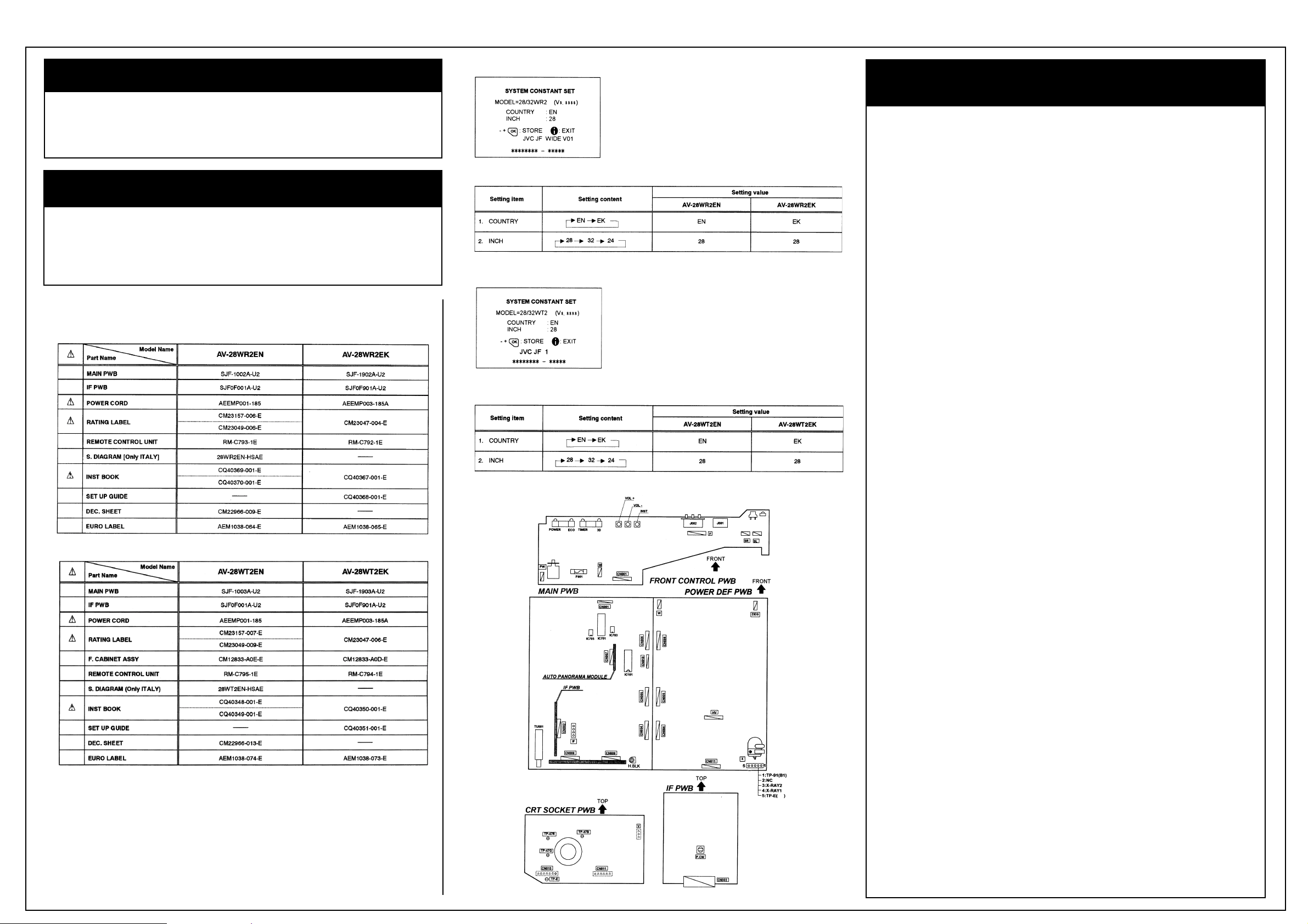
Main Difference List between AV-28WR2 EN and AV-28WR2 EK
Main Difference List between AV-28WT2 EN and AV-28WT2 EK
System Constant Set [AV 28WR2 EN]
Setting Values of System Constant Set [AV 28WR2 EN/EK]
System Constant Set [AV 28WT2 EN]
Setting Values of System Constant Set [AV 28WT2 EN/EK]
Adjustment Locations [AV 28WR2 EN/EK]
JVC AV 28WR2 EK/EN
8. If the picture is not the best when adjusted,
make fine adjustment until you get the best
picture.
9. Press the MENU key and memorize the
setting value.
DEFLECTION CIRCUIT ADJUSTMENT
There are 6 modes of the adjustment
(1) 50Hz mode
(1) PANORAMIC
(2) ULL
(3) REGULAR
(4)14:9 ZOOM
(5)16:9 ZOOM
(6)16:ZOOM SUB TITLE)
(2) 60Hz mode
(each aspect mode) depending upon the kind of
signals (vertical frequency 50Hz / 60Hz).
When the 50Hz PANORAMIC mode has been
established, the setting of other modes will be
done automatically.
However, if the picture quality has not been
optimized, adjust each mode again, respectively.
The adjustment using the remote control unit is
made on the basis of the initial setting values.
The setting values which adjust the screen to
the optimum condition can be different from the
Initial setting values.
Adjustments Cont’d
Adjustment Locations [AV 28WT2 EN/EK]
VIDEO/CHROMA CIRCUIT ADJUSTMENT
The setting (adjustment) using the REMOTE CONTROL UNIT is made on the basis of the initial
setting values. The setting values which adjust the screen to the optimum condition can be different
from the initial setting values.
SECAM COLOUR
[Method of adjustment without measuring instrument]
1. Receive a SECAM full field colour bar signal (75% white).
2. Set the initial setting value of SECAM COLOUR with the UNCTION
-/+
key.
3. Adjust SECAM COLOUR and bring the value of (A) of the illustration to +5V.
4. Press the MENU key and memorize the setting value.
NTSC COLOUR ADJUSTMENTS
(NTSC 3 58 COLOUR)
1. Input a NTSC 3.58MHz COMPOSITE VIDEO
signal (full field colour bar with 75% white)
from the EXT terminal.
2. Set the initial setting value of NTSC 3.58
COLOUR with the UNCTION -/+ key.
3. Adjust NTSC 3.58 COLOUR and bring the
value of (A) of the illustration to +8V(W~B)
[AV-28WR2 EK] or 0V(W~B) [AV-28WT2 EK].
4. Press the MENU key and memorize the
setting value.
TINT ADJUSTMENTS
[NTSC 3 58 TINT]
1. Input a NTSC 3.58MHz COMPOSITE VIDEO
signal (full field colour bar with 75% white)
from the EXT terminal.
2. Select 2.V/C from the SERVICE MENU.
3. Select 6.TINT with the UNCTION UP/DOWN
key.
4. Set the initial setting value of NTSC 3.58
TINT with the UNCTION - or
+
key.
5. Connect the oscilloscope between TP-47B
and TP-E(***)
6. Adjust NTSC 3.58 TINT to bring the value of
(A) in the illustration to +3V [AV-28WR2 EK]
or +5V [AV-28WT2 EK] (voltage difference
between white (W) and magenta (Mg)).
7. Press the MENU key and memorize the
setting value.
Adjustment of BLACK OFFSET (SECAM) I
Measuring Instrument
Remote control unit
Adjustment Part
7. BLACK O SET
(R-Y)***
(B-Y)***
1. Receive a SECAM broadcast.
2. Select 2. V/C from SERVICE MENU.
3. Select 7. BLACK O SET with the UNC-
TION UP/DOWN key.
4. Set the initial setting value for BLACK
O SET (R-Y) and (B-Y) with 4 and 7 or 6
and 9 keys of the remote control.
5. If the picture is not the best with the initial
setting value, make fine adjustment until you
get the best picture.
6. Press the MENU key and memorize the
setting value.
Adjustment of BLACK OFFSET (SECAM) II
Measuring Instrument
Signal generator
Oscilloscope
Remote control unit
Test Point
35 PIN (R-Y)
38 PIN (B-Y)
IC-101 O MAIN PWB
Ajustment Part
7. BLACK O SET
(R-Y)***
(B-Y)***
1. Receive a SECAM COLOUR bar signal (full
field colour bar 75% white).
2. Select 2. V/C from SERVICE MENU.
3. Select 7. BLACK O SET with the UNC-
TION UP/DOWN key.
4. Connect the oscilloscope between 35 pin of
IC-101 and TP-E (***)
5. By using 4 and 7 keys of the remote control,
adjust the BLACK O SET (R-Y) so that it
becomes the waveform changes from (a) to
(b) shown in the figure.
6. Connect the oscilloscope between 36 pin of
IC-101 and TP-E.
7. By using 6 and 9 keys of the remote control,
adjust the BLACK O SET (B-Y) so that it
becomes the waveform changes from (c) to
(d) shown in the figure.
[AV-28WR2EN/EK]
JVC AV 28WR2 EK/EN
Adjustments Cont’d
[AV-28WT2EN/EK]
Adjustment of H SIZE [AV 28WT2 EN/EK]
For more adjustments please refer to matrix
CRT Diagram
[AV-28WR2EN/EK]
This area is intentionally left blank
JVC AV 28WR2 EK/EN
Main Diagram [AV-28WR2EN/EK]
JVC AV 28WR2 EK/EN
Main Diagram “A”
[AV-28WTEN/EK]
JVC AV 28WR2 EK/EN
Main Diagram “B”
[AV-28WTEN/EK]
JVC AV 28WR2 EK/EN
Main Diagram “C”
[AV-28WTEN/EK]
JVC AV 28WR2 EK/EN
Main Diagram “D”
[AV-28WTEN/EK]
JVC AV 28WR2 EK/EN
CRT Diagram “A”
[AV-28WTEN/EK]
JVC AV 28WR2 EK/EN
CRT Diagram “B”
[AV-28WTEN/EK]