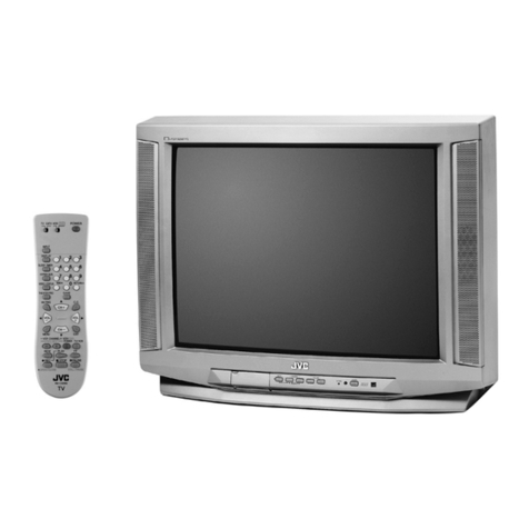
JVC AV-28F3SJ User manual

SERVICE MANUAL
COPYRIGHT © 2005 Victor Company of Japan, Limited No.YA225
2005/2
FLAT COLOUR TELEVISION
YA22520052
AV-28F3SJ
TABLE OF CONTENTS
1 PRECAUTION. . . . . . . . . . . . . . . . . . . . . . . . . . . . . . . . . . . . . . . . . . . . . . . . . . . . . . . . . . . . . . . . . . . . . . . . . 1-4
2 SPECIFIC SERVICE INSTRUCTIONS . . . . . . . . . . . . . . . . . . . . . . . . . . . . . . . . . . . . . . . . . . . . . . . . . . . . . . 1-5
3 DISASSEMBLY . . . . . . . . . . . . . . . . . . . . . . . . . . . . . . . . . . . . . . . . . . . . . . . . . . . . . . . . . . . . . . . . . . . . . . . 1-6
4 ADJUSTMENT . . . . . . . . . . . . . . . . . . . . . . . . . . . . . . . . . . . . . . . . . . . . . . . . . . . . . . . . . . . . . . . . . . . . . . . 1-10
5 TROUBLESHOOTING . . . . . . . . . . . . . . . . . . . . . . . . . . . . . . . . . . . . . . . . . . . . . . . . . . . . . . . . . . . . . . . . . 1-22

1-2 (No.YA225)
SPECIFICATION
Design & specifications are subject to change without notice.
Item Content
Dimensions ( W ×H ×D ) 80.5cm ×49.5cm ×48.6cm
Mass 41.0kg
TV RF System CCIR (I)
Colour System TV Mode PAL
Video Mode PAL / NTSC 3.58 / NTSC 4.43
Sound System A2 / NICAM
Teletext System FLOF (Fastext) / TOP / WST
Receiving Frequency VHF
CATV
46.25MHz - 863.25MHz
S01 - S41
Intermediate Frequency VIF
SIF
38.9MHz (I)
32.9MHz (6.0MHz)
Colour Sub Carrier Frequency PAL (4.43MHz), NTSC (3.58MHz / 4.43MHz)
Power Input AC220V - AC240V, 50Hz
Power Consumption 145W (Max)
Aerial Input Terminal 75Ωunbalanced, coaxial
Picture Tube Size Visible size : 66cm (Measured diagonally) (H: 58.3cm ×V: 33.0cm)
16:9 wide aspect
High Voltage 29kV (at zero bean current)
Speaker Main: 6.0cm ×16cm, Oval type ×2 / Tweeter: 8Ω, 15W) ×2
Audio Output 10W + 10W (THD 10%)
EXT-1 Input / Output 21-pin Euro connector (SCART socket) ×1
EXT-2 Input / Output 21-pin Euro connector (SCART socket) ×1
EXT-3 Input / Output 21-pin Euro connector (SCART socket) ×1
EXT-4 Input Video
Audio (L/R)
1V(p-p) 75Ω, RCA pin jack ×1
500mV(rms) (-4dBs), High Impedance, RCA pin jack ×2
Headphone jack Stereo mini jack 3.5mm ×1
Remote Control Unit VE-30021286 (RM-C1512S), (AA/R06 dry battery ×2)

(No.YA225)1-3
21-PIN EURO CONNECTOR (SCART) : EXT-1 / EXT-2 / EXT-3
(P-P= Peak to Peak, B-W= Blanking to white peak)
Pin No. Signal designation Matching value EXT-1 EXT-2 EXT-3
1 AUDIO R output 500mV(rms) (Nominal),
Low impedance Used (TV OUT) Used (LINE OUT) Not used
2 AUDIO R input 500mV(rms) (Nominal),
High impedance Used (R1) Used (R2) Used (R3)
3 AUDIO L output 500mV(rms) (Nominal),
Low impedance Used (TV OUT) Used (LINE OUT) Not used
4 AUDIO GND --- Used Used Used
5 GND (B) --- Used Used Used
6 AUDIO L input 500mV(rms) (Nominal),
High impedance Used (L1) Used (L2) Used (L3)
7 B input 700mV(B-W), 75 ΩUsed Not used Not used
8 FUNCTION SW (SLOW SW) Low : 0V-3V
High : 8V-12V, High impedance Used Used Used
9 GND (G) --- Used Used Used
10 SCL / T-V LINK --- Not used Used
(SCL / T-V LINK) Not used
11 G input 700mV(B-W), 75 ΩUsed Not used Not used
12 SDA3 --- Not used Used Not used
13 GND (R) --- Used Used Used
14 GND (YS) --- Used Not used Not used
15 R / C input R : 700mV(B-W), 75 Ω
C : 300mV(P-P), 75 ΩUsed (R) Used (C2 / R) Used (C3)
16 Ys input (FAST SW) Low : 0V-0.4V, 75 Ω
High : 1V-3V, 75 ΩUsed Not used Not used
17 GND (VIDEO output) --- Used Used Used
18 GND (VIDEO input) --- Used Used Used
19 VIDEO output 1V(P-P) (Negative sync),75 ΩUsed (TV OUT) Used (LINE OUT) Not used
20 VIDEO / Y input 1V(P-P) (Negative sync), 75 ΩUsed Used Used
21 COMMON GND --- Used Used Used
20 18 16 14 12 10 8 6 4 2
21 19 17 15 13 11 9 7 5 3 1
[Pin assignment]

1-4 (No.YA225)
SECTION 1
PRECAUTION
1.1 SAFETY PRECAUTIONS
(1) The design of this product contains special hardware and many circuits and components specially for safety purposes. For
continued protection, no changes should be made to the original design unless authorized in writing by the manufacturer.
Replacement parts must be identical to those used in the original circuits. Service should be performed by qualified personnel
only.
(2) Alterations of the design or circuitry of the product should not be made. Any design alterations or additions will void the
manufacturer's warranty and will further relieve the manufacturer of responsibility for personal injury or property damage
resulting therefrom.
(3) Many electrical and mechanical parts in the product have special safety-related characteristics. These characteristics are often
not evident from visual inspection nor can the protection afforded by them necessary be obtained by using replacement
components rated for higher voltage, wattage, etc. Replacement parts which have these special safety characteristics are
identified in the Parts List of Service Manual. Electrical components having such features are identified by shading on the
schematics and by ( ) on the Parts List in the Service Manual. The use of a substitute replacement which does not have the
same safety characteristics as the recommended replacement part shown in the Parts List of Service Manual may cause shock,
fire, or other hazards.
(4) The leads in the products are routed and dressed with ties, clamps, tubing's, barriers and the like to be separated from live parts,
high temperature parts, moving parts and / or sharp edges for the prevention of electric shock and fire hazard. When service is
required, the original lead routing and dress should be observed, and it should be confirmed that they have been returned to
normal, after re-assembling.
WARNING
(1) The equipment has been designed and manufactured to meet international safety standards.
(2) It is the legal responsibility of the repairer to ensure that these safety standards are maintained.
(3) Repairs must be made in accordance with the relevant safety standards.
(4) It is essential that safety critical components are replaced by approved parts.
(5) If mains voltage selector is provided, check setting for local voltage.

(No.YA225)1-5
SECTION 2
SPECIFIC SERVICE INSTRUCTIONS
2.1 FEATURES
• It is a remote controlled colour television.
• It can tune cable channels.
• Controlling the TV is very easy by its menu driven system.
• It has Euroconnector sockets for external device (such as
video recorder, video games, audio set, etc.)
• Stereo sound systems are available.
• Full function Teletext (Fastext, Toptext, WST).
• AUTO PROGRAM (Automatic Programming System).
• All programs can be named.
• Forward or backward automatic tuning.
• Sleep timer.
• Child Lock.
• Blue Background
• Panoramic mode
• Comb FIlter
• CTI (Colour Transient Improvement)
•T-VLink
• Automatic sound muting when no transmission.
• 5 minutes after the broadcasting (close down), the TV switches
itself automatically to stand-by mode.
• WSS (Wide Screen Signaling)

1-6 (No.YA225)
SECTION 3
DISASSEMBLY
3.1 DISASSEMBLY PROCEDURE
3.1.1 REMOVING THE REAR COVER
(1) Unplug the power cord.
(2) Remove the 8 screws [A].
(3) Remove the 4 screws [B].
(4) Withdraw the REAR COVER toward you.
3.1.2 REMOVING THE BACK DOOR
• Remove the REAR COVER.
(1) Remove the 2 screws [C].
(2) Withdraw the BACK DOOR toward you.
3.1.3 REMOVING THE SPEAKER and TWEETER
• Remove the REAR COVER.
(1) Remove the 4 screws [D], and remove the SPEAKER.
(2) Remove the other hand SPEAKER in the same steps.
(3) Remove the 2 screws [E], and remove the TWEETER.
(4) Remove the other hand TWEETER in the same steps.
3.1.4 REMOVING THE MAIN PWB
• Remove the REAR COVER.
• Remove the BACK DOOR.
(1) Remove the 4 screws [F].
(2) Slightly raise the both sides of the MAIN PWB by hand and
withdraw the MAIN PWB backward.
[CAUTION]
If necessary, take off the wire clamp, connectors etc.
Be careful enough when developing a MAIN PWB.
3.1.5 REMOVING THE SIDE CONTROL PWB
• Remove the REAR COVER.
(1) Remove the 2 screws [G].
(2) Remove the SIDE CONTROL PWB.
3.1.6 REMOVING THE FRONT AV & HEADPHONE JACK
PWB
• Remove the REAR COVER.
(1) Remove the 2 screws [H].
(2) Remove the FRONT AV & HEADPHONE JACK PWB.
3.1.7 REMOVING THE POWER SWITCH PWB
• Remove the REAR COVER.
(1) Remove the 2 screws [I], and remove the POWER
SWITCH PWB.
3.1.8 REMOVING THE LED PWB
• Remove the REAR COVER.
(1) Remove the 2 screws [J], and remove the LED PWB.
3.1.9 CHECKING THE PW BOARD
• To check the back side of the PW Board.
(1) Pull out the PW Board. (Refer to REMOVING THE MAIN
PWB).
(2) Erect the PW Board vertically so that you can easily check
the back side of the PWB.
[CAUTION]
• When erecting the PW Board, be careful so that there will be
no contacting with other PW Board.
• Before turning on power, make sure that the wire connector
is properly connected.
• When conducting a check with power supplied, be sure to
confirm that the CRT EARTH WIRE (BRAIDED ASS'Y) is
connected to the CRT SOCKET PWB.
3.1.10 WIRE CLAMPING AND CABLE TYING
(1) Be sure to clamp the wire.
(2) Never remove the cable tie used for tying the wires
together.
Should it be inadvertently removed, be sure to tie the wires
with a new cable tie.
(No.YA225)1-7
Fig.1
F
D
E
G
H
TWEETER
SPEAKER
LED PWB
POWER SWITCH PWB FRONT AV & HEADPHONE
JACK PWB
SIDE CONTROL PWB
REAR COVER
(x8)
(x4)
(x2)
(x4)
(x2)
(x4)
(x2)
(x2)
BACK DOOR
MAIN PWB
CRT SOCKET PWB
CHASSIS BASE
A
B
C
(x2)
I
(x2)
J
PICTURE TUBE

1-8 (No.YA225)
3.2 SETTING OF THE LAST MEMORY FOR SHIPMENT
3.2.1 USER SETTING VALUES
3.2.2 SETTING A.P.S. (AUTO STORE)
(1) Press [MENU] key on the remote control unit to display the main menu.
(2) Press []/[] keys to select "PROGRAM" item, them []/[] keys to display the "PROGRAM" menu.
(3) Press the [BLUE] key to enter the AUTOSTORE mode.
(4) Press []/[] keys to choose the "COUNTRY", then press []/[] keys the choose country you are nou located.
(5) Press []/[] keys to choose the "CONTINUE", then press [] key to start AUTO PROGRAM. The message screen appears.
NOTE :
To cancel the AUTO PROGRAM, press the [PICTURE] key on the remote control unit.
(6) After AUTO PROGRAM is finalized, the PROGRAM menu appears again.
(7) Press the [PICTURE] key on the remote control unit to exit main menu.
Setting item Setting value Setting item Setting value
PICTURE MENU INSTALL. MENU
BRIGHTNESS These adjust are automatically
restored when AUTO PROGRAM
bit in Service menu is set.
The procedure for setting AUTO
PROGRAM bit is described.
PROGRAMME
Refer to instruction book
CONTRAST BAND
COLOUR CHANNEL
SHARPNESS STANDARD
HUE (only NTSC) COLOUR SYSTEM
PICTURE MODE USER DECODER (EXT-2)
COLOUR TEMP NORMAL FINE TUNING
ZOOM AUTO SEARCH
STORE
SOUND MENU FEATURE MENU
BALANCE Center SLEEP TIMER OFF
BASS Center CHILD LOCK OFF
TREBLE Center LANGUAGE ENGLISH
HYPER SOUND OFF EXT-2 OUTPUT TV
BLUE BACKGROUND ON

(No.YA225)1-9
3.3 REPLACEMENT OF CHIP COMPONENT
3.3.1 CAUTIONS
(1) Avoid heating for more than 3 seconds.
(2) Do not rub the electrodes and the resist parts of the pattern.
(3) When removing a chip part, melt the solder adequately.
(4) Do not reuse a chip part after removing it.
3.3.2 SOLDERING IRON
(1) Use a high insulation soldering iron with a thin pointed end of it.
(2) A 30w soldering iron is recommended for easily removing parts.
3.3.3 REPLACEMENT STEPS
1. How to remove Chip parts
[Resistors, capacitors, etc.]
(1) As shown in the figure, push the part with tweezers and
alternately melt the solder at each end.
(2) Shift with the tweezers and remove the chip part.
[Transistors, diodes, variable resistors, etc.]
(1) Apply extra solder to each lead.
(2) As shown in the figure, push the part with tweezers and
alternately melt the solder at each lead. Shift and remove
the chip part.
NOTE :
After removing the part, remove remaining solder from the
pattern.
2. How to install Chip parts
[Resistors, capacitors, etc.]
(1) Apply solder to the pattern as indicated in the figure.
(2) Grasp the chip part with tweezers and place it on the
solder. Then heat and melt the solder at both ends of the
chip part.
[Transistors, diodes, variable resistors, etc.]
(1) Apply solder to the pattern as indicated in the figure.
(2) Grasp the chip part with tweezers and place it on the
solder.
(3) First solder lead Aas indicated in the figure.
(4) Then solder leads Band C.
SOLDER SOLDER
A
B
C
A
B
C

1-10 (No.YA225)
SECTION 4
ADJUSTMENT
4.1 ADJUSTMENT PREPARATION
(1) You can make the necessary adjustments for this unit with
either the Remote Control Unit or with the adjustment tools
and parts as given below.
(2) Adjustment with the Remote Control Unit is made on the
basis of the initial setting values, however, the new setting
values which set the screen to its optimum condition may
differ from the initial settings.
(3) Make sure that AC power is turned on correctly.
(4) Turn on the power for set and test equipment before use,
and start the adjustment procedures after waiting at least
30 minutes.
(5) Unless otherwise specified, prepare the most suitable
reception or input signal for adjustment.
(6) Never touch any adjustment parts which are not specified
in the list for this adjustment - variable resistors,
transformers, condensers, etc.
(7) Presetting before adjustment.
Unless otherwise specified in the adjustment instructions,
preset the following functions with the remote control unit:
4.2 MEASURING EQUIPMENT
(1) DC voltmeter (or digital voltmeter)
(2) Signal generator (Pattern generator)
: [PAL / SECAM / NTSC]
(3) Remote control unit
4.3 ADJUSTMENT ITEM
• FOCUS ADJUSTMENT
• SCREEN ADJUSTMENT
• AGC ADJUSTMENT
• DEFLECTION CIRCUIT ADJUSTMENT
• VIDEO CIRCUIT ADJUSTMENT
4.4 ADJUSTMENT LOCATIONS
Setting item Setting value
BRIGHTNESS
Center
CONTRAST
COLOUR
SHARPNESS
COLOUR TEMP NORMAL
ZOOM AUTO
SIDE CONTROL PWB
TUNER
TU200
IC502 (MEMORY)
IC500 (MI-COM)
MAIN PWB
FRONT
FBT
UPPER : FOCUS
LOWER : SCREEN
TOP
EXT-1/EXT-2
EXT-3
MENU
P/CH
FRONT AV &
HEADPHONE
JACK PWB
POWER SWITCH
PWB
POWER SWITCH
FUSE
HEADPHONE
VIDEO

(No.YA225)1-11
4.5 BASIC OPERATION OF SERVICE MODE
4.5.1 HOW TO ENTER THE SERVICE MODE
(1) Press the [INFORMATION] key and [MUTING] key
simultaneously in the main menu, and the SERVICE
MENU screen (Fig.1) will be displayed.
Fig.1
(2) While the SERVICE MENU screen is displayed, press the
[]/[] and []/[] key and select the "ADJUST...", then
ADJUST MENU screen (Fig.2) will be displayed.
Fig.2
4.5.2 SELECTION OF ADJUSTMENT ITEMS
(1) Enter the SERVICE MODE.
(2) Press the FUNCTION []/[] key to select the adjustment
item.
(3) Press the FUNCTION []/[] key to set the setting value.
(4) The setting value will be stored auto matically when
release the REMOTE CONTROL UNIT keys.
4.5.3 HOW TO EXIT SERVICE MODE
(1) Press the [MENU] key.
SERVICE
ADJUST...
OPTIONS...
*********
*********
SERVICE MENU
Select for adjustment Do not adjust
ADJUST...
SETTING ITEM No. SETTING VALUE
000
001
002
003
004
005
006
007
008
009
***
***
***
***
***
***
***
***
***
***
ADJUST MENU
MUTING key
REMOTE CONTROL UNIT key NAME
INFORMATION key
UP / DOWN
[ ]/[ ] key
MENU key
(EXIT SERVICE MENU)
LEFT / RIGHT
[ ]/[ ] key
STAND BY/POWER
DIRECT PROGRAM

1-12 (No.YA225)
4.5.4 SERVICE MENU SCREEN
Do Not Adjust
SERVICE
ADJUST...
OPTIONS...
*********
*********
SERVICE MENU
ADJUST...
SETTING ITEM No.
000~155
SETTING VALUE
000
001
002
003
004
005
006
007
008
009
***
***
***
***
***
***
***
***
***
***
ADJUST MENU
OPTIONS..
SETTING ITEM No.
000~063
SETTING VALUE
000
001
002
003
004
005
006
007
008
009
**
**
**
**
**
**
**
**
**
**
********
********
********
********
********
********
********
********
********
********
OPTIONS MENU
NOTE:
Do not adjust the OPTIONS MENU. If you change the setting value, the set will not function correctly.

(No.YA225)1-13
4.6 ADJUSTMENTS PROCEDURE
4.6.1 FOCUS ADJUSTMENT
4.6.2 SCREEN ADJUSTMENT
4.6.3 AGC ADJUSTMENT
Item Measuring
instrument Test point Adjustment part Description
FOCUS
adjustment
Signal
generator
Remote
control unit
FOCUS VR
[On the FBT]
(1) Receive a PAL crosshatch signal.
(2) Adjust FOCUS VR on the FBT as thin as possible.
FBT
FOCUS VR
SCREEN VR
Item Measuring
instrument Test point Adjustment part Description
SCREEN
adjustment
Remote
control unit
002
SCREEN VR
[On the FBT]
(1) Enter the OPTIONS MENU.
(2) Select option No.002 and change bit 6 from 0 to 1
disabling vertical scan. Then horizontal line appears.
(3) Adjust horizontal line as thin as possible via screen
adjust pot.
(4) Press number 0 key to leave service menu.
Item Measuring
instrument Test point Adjustment part Description
AGC
adjustment
Signal
generator
Remote
control unit
DC volt meter
003 (1) Receive a PAL signal at 60dBµV RF signal level.
(2) Enter the SERVICE MENU.
(3) Select ADJUST MENU.
(4) Select 003.
(5) Adjust 003 by pressing until voltage at pin 1 of
TUNER is equal to 3.0V.

1-14 (No.YA225)
4.6.4 DEFLECTION CIRCUIT ADJUSTMENT
Item Measuring
instrument Test point Adjustment part Description
VERTICAL
POSITION
adjustment
Signal
generator
Remote
control unit
030 (REGULAR)
040 (PANORAMIC)
050 (14:9 ZOOM)
060 (16:9 ZOOM)
070 (16:9 ZOOM
SUBTITLE)
110 (FULL)
(1) Receive a PAL circle pattern signal.
(2) Enter the SERVICE MODE.
(3) Select ADJUST MENU.
(4) Select 030.
(5) Adjust 030 to make A=B.
(6) Check and readjust 030 item if the adjustment
becomes improper after some other geometric
adjustments are done.
(7) Select 040 (PANORAMIC).
(8) Adjust 040 in the same procedure.
(9) Select 050 (14:9 ZOOM).
(10) Adjust 050 in the same procedure.
(11) Select 060 (16:9 ZOOM).
(12) Adjust 060 in the same procedure.
(13) Select 070 (16:9 ZOOM SUBTITLE).
(14) Adjust 070 in the same procedure.
(15) Select 110 (FULL).
(16) Adjust 110 in the same procedure.
VERTICAL
SIZE
adjustment
Signal
generator
Remote
control unit
031 (REGULAR)
041 (PANORAMIC)
051 (14:9 ZOOM)
061 (16:9 ZOOM)
071 (16:9 ZOOM
SUBTITLE)
111 (FULL)
(1) Receive a PAL crosshatch signal.
(2) Enter the SERVICE MODE.
(3) Select ADJUST MENU.
(4) Select 031 (REGULAR).
(5) Adjust 031 until horizontal black lines on both the
upper and lower part of the crosshatch pattern
become very closeted the upper and lower
horizontal sides of picture size and nearly about to
disappear.
(6) Check and readjust 031 item if the adjustment
becomes improper after some other geometric
adjustments are done.
(7) Select 041 (PANORAMIC).
(8) Adjust 041 in the same procedure.
(9) Select 051 (14:9 ZOOM).
(10) Adjust 051 in the same procedure.
(11) Select 061 (16:9 ZOOM).
(12) Adjust 061 in the same procedure.
(13) Select 071 (16:9 ZOOM SUBTITLE).
(14) Adjust 071 in the same procedure.
(15) Select 111 (FULL).
(16) Adjust 111 in the same procedure.
A
B
Screen
size
Very close
Very close
Picture
size
100%

(No.YA225)1-15
VERTICAL
S-CORRECTION
& LINEARITY
adjustment
Signal
generator
Remote
control unit
032 (REGULAR)
033 (REGULAR)
042 (PANORAMIC)
043 (PANORAMIC)
052 (14:9 ZOOM)
053 (14:9 ZOOM)
062 (16:9 ZOOM)
063 (16:9 ZOOM)
072 (16:9 ZOOM
SUBTITLE)
073 (16:9 ZOOM
SUBTITLE)
112 (FULL)
113 (FULL)
(1) Receive a PAL crosshatch signal.
(2) Enter the SERVICE MODE.
(3) Select ADJUST MENU.
(4) Select 032 (REGULAR).
(5) Adjust 032 until the size of squares on both the
upper and lower part of the crosshatch pattern
become equal to the squares laying on the vertical
center of the crosshatch pattern.
(6) Check and readjust 032 item if the adjustment
becomes improper after some other geometric
adjustments are done.
(7) Select 033 (REGULAR).
(8) Adjust 033 until all the size of squares of the
crosshatch pattern become in equal size from the
top of the screen to its bottom of the whole screen.
(9) Check and readjust 033 item if the adjustment
becomes improper after some other geometric
adjustments (especially after than S-COR
adjustment) are done.
(10) Select 042 (PANORAMIC).
(11) Adjust 042 in the same procedure as (5).
(12) Select 043 (PANORAMIC).
(13) Adjust 043 in the same procedure as (8).
(14) Select 052 (14:9 ZOOM).
(15) Adjust 052 in the same procedure as (5).
(16) Select 053 (14:9 ZOOM).
(17) Adjust 053 in the same procedure as (8).
(18) Select 062 (16:9 ZOOM).
(19) Adjust 062 in the same procedure as (5).
(20) Select 063 (16:9 ZOOM).
(21) Adjust 063 in the same procedure as (8).
(22) Select 072 (16:9 ZOOM SUBTITLE).
(23) Adjust 072 in the same procedure as (5).
(24) Select 073 (16:9 ZOOM SUBTITLE).
(25) Adjust 073 in the same procedure as (8).
(26) Select 112 (FULL).
(27) Adjust 112 in the same procedure as (5).
(28) Select 113 (FULL).
(29) Adjust 113 in the same procedure as (8).
HORIZONTAL
POSITION
adjustment
Signal
generator
Remote
control unit
038 (REGULAR)
048 (PANORAMIC)
058 (14:9 ZOOM)
068 (16:9 ZOOM)
078 (16:9 ZOOM
SUBTITLE)
118 (FULL)
(1) Receive a PAL circle pattern signal.
(2) Enter the SERVICE MODE.
(3) Select ADJUST MENU.
(4) Select 038 (REGULAR).
(5) Adjust 038 to make C=D.
(6) Check and readjust 038 item if the adjustment
becomes improper after some other geometric
adjustments are done.
(7) Select 048 (PANORAMIC).
(8) Adjust 048 in the same procedure.
(9) Select 058 (14:9 ZOOM).
(10) Adjust 058 in the same procedure.
(11) Select 068 (16:9 ZOOM).
(12) Adjust 068 in the same procedure.
(13) Select 078 (16:9 ZOOM SUBTITLE).
(14) Adjust 078 in the same procedure.
(15) Select 118 (FULL).
(16) Adjust 118 in the same procedure.
Item Measuring
instrument Test point Adjustment part Description
UPPER
CENTER
LOWER
CD

1-16 (No.YA225)
HORIZONTAL
SIZE
adjustment
Signal
generator
Remote
control unit
039 (REGULAR)
049 (PANORAMIC)
059 (14:9 ZOOM)
069 (16:9 ZOOM)
079 (16:9 ZOOM
SUBTITLE)
119 (FULL)
(1) Receive a PAL crosshatch signal.
(2) Enter the SERVICE MODE.
(3) Select ADJUST MENU.
(4) Select 039 (REGULAR).
(5) Adjust 039 until vertical lines on both the left and
right part of the cross-hatch will be visible nor screen
will be so wide.
(6) Check and readjust 039 item if the adjustment
becomes improper after some other geometric
adjustments are done.
(7) Select 049 (PANORAMIC).
(8) Adjust 049 in the same procedure.
(9) Select 059 (14:9 ZOOM).
(10) Adjust 059 in the same procedure.
(11) Select 069 (16:9 ZOOM).
(12) Adjust 069 in the same procedure.
(13) Select 079 (16:9 ZOOM SUBTITLE).
(14) Adjust 079 in the same procedure.
(15) Select 119 (FULL).
(16) Adjust 119 in the same procedure.
ANGLE
adjustment
Signal
generator
Remote
control unit
016 (1) Receive a PAL crosshatch signal.
(2) Enter the SERVICE MODE.
(3) Select ADJUST MENU.
(4) Select 016.
(5) Adjust 016 until the vertical lines of the crosshatch
pattern become straight.
(6) Check and readjust 016 item if the adjustment
becomes improper after some other geometric
adjustments are done.
BOW
adjustment
Signal
generator
Remote
control unit
017 (1) Receive a PAL crosshatch signal.
(2) Enter the SERVICE MODE.
(3) Select ADJUST MENU.
(4) Select 017.
(5) Adjust 017 until the vertical lines become straight.
(6) Check and readjust 017 item if the adjustment
becomes improper after some other geometric
adjustments are done.
NOTE:
In case where there is a bow-shaped distortion of
images on the screen. (Figure)
Item Measuring
instrument Test point Adjustment part Description
Screen size
Very
close Very
close
Picture size 100%

(No.YA225)1-17
TRAPEZIUM
adjustment
Signal
generator
Remote
control unit
034 (REGULAR)
044 (PANORAMIC)
054 (14:9 ZOOM)
064 (16:9 ZOOM)
074 (16:9 ZOOM
SUBTITLE)
114 (FULL)
(1) Receive a PAL crosshatch signal.
(2) Enter the SERVICE MODE.
(3) Select ADJUST MENU.
(4) Select 034 (REGULAR).
(5) Adjust 034 until vertical lines, especially lines at the
sides of the picture frame become parallel to the
both sides of picture tubes as close as possible.
(6) Check and readjust 034 item if the adjustment
becomes improper after some other geometric
adjustments are done.
(7) Select 044 (PANORAMIC).
(8) Adjust 044 in the same procedure.
(9) Select 054 (14:9 ZOOM).
(10) Adjust 054 in the same procedure.
(11) Select 064 (16:9 ZOOM).
(12) Adjust 064 in the same procedure.
(13) Select 074 (16:9 ZOOM SUBTITLE).
(14) Adjust 074 in the same procedure.
(15) Select 114 (FULL).
(16) Adjust 114 in the same procedure.
SIDE PIN
adjustment
Signal
generator
Remote
control unit
035 (REGULAR)
045 (PANORAMIC)
055 (14:9 ZOOM)
065 (16:9 ZOOM)
075 (16:9 ZOOM
SUBTITLE)
115 (FULL)
(1) Receive a PAL crosshatch signal.
(2) Enter the SERVICE MODE.
(3) Select ADJUST MENU.
(4) Select 035 (REGULAR).
(5) Adjust 035 until vertical lines close to the both sides
of the picture frame become parallel to vertical sides
of picture tube without any bending to left or to right
side of the screen.
(6) Check and readjust 035 item if the adjustment
becomes improper after some other geometric
adjustments are done.
(7) Select 045 (PANORAMIC).
(8) Adjust 045 in the same procedure.
(9) Select 055 (14:9 ZOOM).
(10) Adjust 055 in the same procedure.
(11) Select 065 (16:9 ZOOM).
(12) Adjust 065 in the same procedure.
(13) Select 075 (16:9 ZOOM SUBTITLE).
(14) Adjust 075 in the same procedure.
(15) Select 115 (FULL).
(16) Adjust 115 in the same procedure.
Item Measuring
instrument Test point Adjustment part Description
Parallel
Parallel

1-18 (No.YA225)
CORNER
adjustment
Signal
generator
Remote
control unit
036 (REGULAR)
037 (REGULAR)
046 (PANORAMIC)
047 (PANORAMIC)
056 (14:9 ZOOM)
057 (14:9 ZOOM)
066 (16:9 ZOOM)
067 (16:9 ZOOM)
076 (16:9 ZOOM
SUBTITLE)
077 (16:9 ZOOM
SUBTITLE)
116 (FULL)
117 (FULL)
(1) Receive a PAL crosshatch signal.
(2) Enter the SERVICE MODE.
(3) Select ADJUST MENU.
(4) Select 036 (REGULAR).
(5) Adjust 036 until vertical lines at the upper corners of
the picture frame become vertical and parallel to
vertical corner sides of picture tube.
(6) Check and readjust 036 item if the adjustment
becomes improper after some other geometric
adjustments are done.
(7) Select 037 (REGULAR).
(8) Adjust 037 until vertical lines at the lower corners of
the picture frame become vertical and parallel to
vertical corner sides of picture tube.
(9) Check and readjust 037 item if the adjustment
becomes improper after some other geometric
adjustments are done.
(10) Select 116 (FULL).
(11) Adjust 116 in the same procedure as (5).
(12) Select 117 (FULL).
(13) Adjust 117 in the same procedure as (8).
ROTATION
adjustment
Signal
generator
Remote
control unit
083 (1) Receive a PAL crosshatch signal.
(2) Enter the SERVICE MODE.
(3) Select ADJUST MENU.
(4) Select 083.
(5) Adjust 083 to rotate the complete master clockwise
and counter clockwise depending on the CRT.
(6) Check and readjust 083 item if the adjustment
becomes improper after some other geometric
adjustments are done.
Item Measuring
instrument Test point Adjustment part Description
Straight Straight

(No.YA225)1-19
NTSC
HORIZONTAL
SIZE
adjustment
Signal
generator
Remote
control unit
135 (REGULAR)
142 (FULL)
(1) Receive a NTSC crosshatch signal.
(2) Enter the SERVICE MODE.
(3) Select ADJUST MENU.
(4) Select 135 (REGULAR).
(5) Adjust 135 until vertical lines on both the left and
right part of the cross-hatch will be visible nor screen
will be so wide.
(6) Check and readjust TRAPEZ item if the adjustment
becomes improper after some other geometric
adjustments are done.
(7) Select 142 (FULL).
(8) Adjust 142 in the same procedure.
NTSC
SIDE PIN
adjustment
Signal
generator
Remote
control unit
136 (REGULAR) (1) Receive a NTSC crosshatch signal.
(2) Enter the SERVICE MODE.
(3) Select ADJUST MENU.
(4) Select 136 (REGULAR).
(5) Adjust 136 until vertical lines close to the both sides
of the picture frame become straight to vertical sides
of picture tube without any bending to left or to right
side of the screen.
(6) Check and readjust 136 item if the adjustment
becomes improper after some other geometric
adjustments are done.
TELETEXT
SCREEN SIZE
adjustment
Signal
generator
Remote
control unit
143 (1) Receive a PAL crosshatch signal.
(2) Enter the SERVICE MODE.
(3) Select ADJUST MENU.
(4) Select 143.
(5) Adjust 143 to adjust the proper vertical size of
Teletext screen.
(6) Check and readjust 143 item if the adjustment
becomes improper after some other geometric
adjustments are done.
Item Measuring
instrument Test point Adjustment part Description
Screen size
Very
close Very
close
Picture size 100%
Straight

1-20 (No.YA225)
NTSC
HORIZONTAL
SIZE
adjustment
Signal
generator
Remote
control unit
135
142 (16:9 mode)
(1) Receive a NTSC crosshatch signal.
(2) Enter the SERVICE MODE.
(3) Select ADJUST MENU.
(4) Select 135.
(5) Adjust 135 until vertical lines on both the left and
right part of the cross-hatch will be visible nor screen
will be so wide.
(6) Check and readjust TRAPEZ item if the adjustment
becomes improper after some other geometric
adjustments are done.
(7) Select 142 (16:9 mode).
(8) Adjust 142 in the same procedure.
NTSC
SIDE PIN
adjustment
Signal
generator
Remote
control unit
136 (1) Receive a NTSC crosshatch signal.
(2) Enter the SERVICE MODE.
(3) Select ADJUST MENU.
(4) Select 136.
(5) Adjust 136 until vertical lines close to the both sides
of the picture frame become straight to vertical sides
of picture tube without any bending to left or to right
side of the screen.
(6) Check and readjust 136 item if the adjustment
becomes improper after some other geometric
adjustments are done.
TELETEXT
SCREEN SIZE
adjustment
Signal
generator
Remote
control unit
143 (1) Receive a PAL crosshatch signal.
(2) Enter the SERVICE MODE.
(3) Select ADJUST MENU.
(4) Select 143.
(5) Adjust 143 to adjust the proper vertical size of
Teletext screen.
(6) Check and readjust 143 item if the adjustment
becomes improper after some other geometric
adjustments are done.
Item Measuring
instrument Test point Adjustment part Description
Screen size
Very
close Very
close
Picture size 100%
Straight
Other manuals for AV-28F3SJ
5
Table of contents
Other JVC TV manuals

JVC
JVC AV-21PS4N User manual

JVC
JVC AV-25BT6ENB User manual

JVC
JVC I' Art AV-27F702 User manual

JVC
JVC HV-32D25EUW User manual

JVC
JVC AV-27750 User manual

JVC
JVC LT-32EC3208 User manual

JVC
JVC AV-1416EE User manual

JVC
JVC AV29A10EUS User manual

JVC
JVC AV-48P575 Series User manual

JVC
JVC AV-36F703/Y User manual

JVC
JVC AV-21D114/B Administrator Guide

JVC
JVC AV-21V511 User manual

JVC
JVC AV-21AT User manual

JVC
JVC AV-20RM4SE User manual

JVC
JVC LT-26HG45EAQ User manual

JVC
JVC AV-27D303 User manual

JVC
JVC AV-20F475S User manual

JVC
JVC InteriArt AV-28E50SK User manual

JVC
JVC AV28S2EKGR User manual

JVC
JVC AV-29J334/V User manual