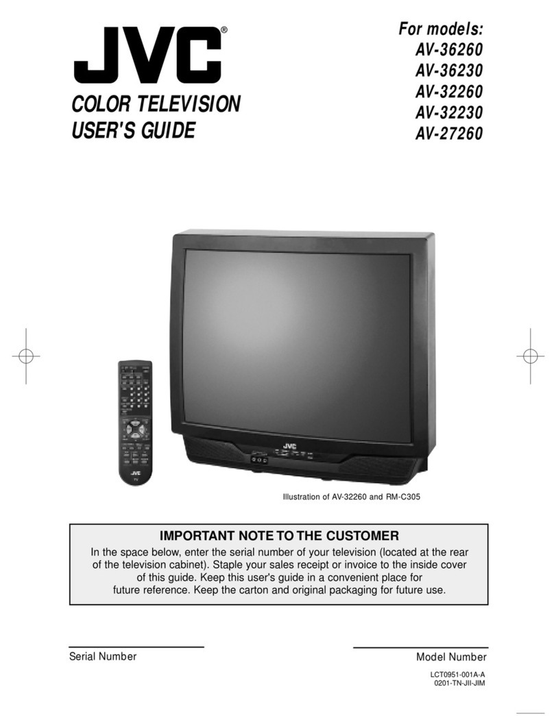
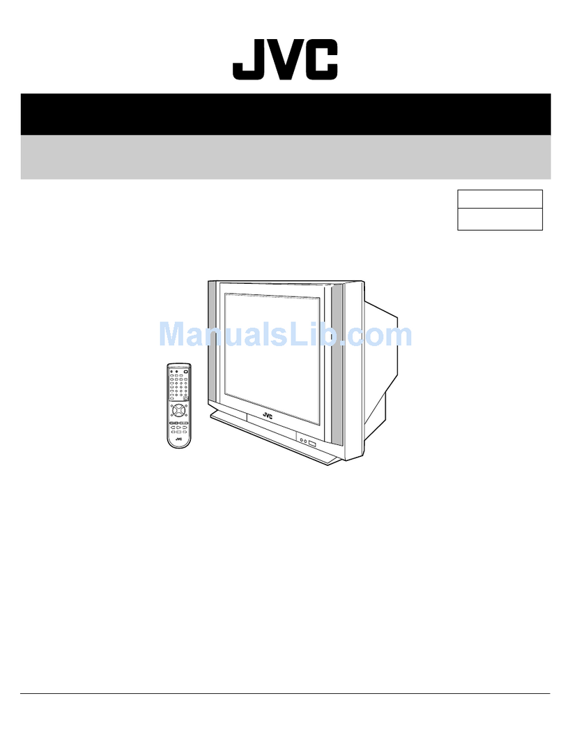
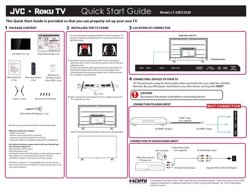
JVC AV-32360 User manual

No.51951
May 2002
AV-32360 AV-32S3
6
AV-32330 AV-32S3
3
AV-3232
0
1COPYRIGHT © 2002 VICTOR COMPANY OF JAPAN, LTD.
AV-32360/M /R /Y AV-32S36
/M /R /Y
AV-32330/M /R /Y AV-32S33
/M /R /Y
AV-32320/M /R /Y
CONTENTS
!SPECIFICATIONS ・・・・・・・・・・・・・・・・・・・・・・・・・・・・・・・・
・・・・・・・・・・・・・・・・・・・・・・・・・・・・・・・・・・・・・・・・・・・・・・・・・・・・・・・・・・・・・・・・
・・・・・・・・・・・・・・・・・・・・・・・・・・・・・・・・・・・・・・・・・・・・・・・・・・・・・・・・・・・・・・・・
・・・・・・・・・・・・・・・・・・・・・・・・・・・・・・・・・・・・・・・・・・・・・・・・・・・・・・・・・・・・・・・・
・・・・・・・・・・・・・・・・・・・・・・・・・・・・・・・・・・・・・・
・・・・・・・・・・・・
・・・・・・2
!SAFETY PRECAUT IONS ・・・・・・・・・・・・・・・・・・・・・・・・・・・・・・・・
・・・・・・・・・・・・・・・・・・・・・・・・・・・・・・・・・・・・・・・・・・・・・・・・・・・・・・・・・・・・・・・・
・・・・・・・・・・・・・・・・・・・・・・・・・・・・・・・・・・・・・・・・・・・・・・・・・・・・・・・・・・・・・・・・
・・・・・・・・・・・・・・・・・・・・・・・・・・・・・・・・・・・・・・・・・・・・・・・・・・・・・・・・・・・・・・・・
・・・・・・・・・・・・・・・・・・・・・・・・・・・・・・・・3
!FEATURES・・・・・・・・・・・・・・・・・・・・・・・・・・・・・・・・
・・・・・・・・・・・・・・・・・・・・・・・・・・・・・・・・・・・・・・・・・・・・・・・・・・・・・・・・・・・・・・・・
・・・・・・・・・・・・・・・・・・・・・・・・・・・・・・・・・・・・・・・・・・・・・・・・・・・・・・・・・・・・・・・・
・・・・・・・・・・・・・・・・・・・・・・・・・・・・・・・・・・・・・・・・・・・・・・・・・・・・・・・・・・・・・・・・
・・・・・・・・・・・・・・・・・・・・・・・・・・・・・・・・・・・・・・・・・・・・
・・・・・・・・・・・・・・・・・・・・・・・・
・・・・・・・・・・・・4
!FUNCTIONS ・・・・・・・・・・・・・・・・・・・・・・・・・・・・・・・・
・・・・・・・・・・・・・・・・・・・・・・・・・・・・・・・・・・・・・・・・・・・・・・・・・・・・・・・・・・・・・・・・
・・・・・・・・・・・・・・・・・・・・・・・・・・・・・・・・・・・・・・・・・・・・・・・・・・・・・・・・・・・・・・・・
・・・・・・・・・・・・・・・・・・・・・・・・・・・・・・・・・・・・・・・・・・・・・・・・・・・・・・・・・・・・・・・・
・・・・・・・・・・・・・・・・・・・・・・・・・・・・・・・・・・・・・・・・・・・
・・・・・・・・・・・・・・・・・・・・・・
・・・・・・・・・・・4
!MAIN DIFFERENCE LIST ・・・・・・・・・・・・・・・・・・・・・・・・・・・・・・・・
・・・・・・・・・・・・・・・・・・・・・・・・・・・・・・・・・・・・・・・・・・・・・・・・・・・・・・・・・・・・・・・・
・・・・・・・・・・・・・・・・・・・・・・・・・・・・・・・・・・・・・・・・・・・・・・・・・・・・・・・・・・・・・・・・
・・・・・・・・・・・・・・・・・・・・・・・・・・・・・・・・・・・・・・・・・・・・・・・・・・・・・・・・・・・・・・・・
・・・・・・・・・・・・・・・・・・・・・・・・・・・・・・・・6
!HOW TO INDENTIFY MODELS・・・・・・・・・・・・・・・・・・・・・・・・・・・・・・・・
・・・・・・・・・・・・・・・・・・・・・・・・・・・・・・・・・・・・・・・・・・・・・・・・・・・・・・・・・・・・・・・・
・・・・・・・・・・・・・・・・・・・・・・・・・・・・・・・・・・・・・・・・・・・・・・・・・・・・・・・・・・・・
・・・・・・・・・・・・・・・・・・・・・・・・・・・・・・・・・・・・・・・・・・・・・・・・・・・・・・・・
・・・・・・・・・・・・・・・・・・・・・・・・・・・・7
!SPECIFIC SERVICE INSTRUCTIONS ・・・・・・・・・・・・・・・・・・・・・・・・・・・・・・・・
・・・・・・・・・・・・・・・・・・・・・・・・・・・・・・・・・・・・・・・・・・・・・・・・・・・・・・・・・・・・・・・・
・・・・・・・・・・・・・・・・・・・・・・・・・・・・・・・・・・・・・・・・・・・・・・・・・・・・・・
・・・・・・・・・・・・・・・・・・・・・・・・・・・・・・・・・・・・・・・・・・・・
・・・・・・・・・・・・・・・・・・・・・・8
!SERVICE ADJUSTMENTS ・・・・・・・・・・・・・・・・・・・・・・・・・・・・・・・・
・・・・・・・・・・・・・・・・・・・・・・・・・・・・・・・・・・・・・・・・・・・・・・・・・・・・・・・・・・・・・・・・
・・・・・・・・・・・・・・・・・・・・・・・・・・・・・・・・・・・・・・・・・・・・・・・・・・・・・・・・・・・・・・
・・・・・・・・・・・・・・・・・・・・・・・・・・・・・・・・・・・・・・・・・・・・・・・・・・・・・・・・・・・・
・・・・・・・・・・・・・・・・・・・・・・・・・・・・・・14
!PARTS LIST ・・・・・・・・・・・・・・・・・・・・・・・・・・・・・・・・
・・・・・・・・・・・・・・・・・・・・・・・・・・・・・・・・・・・・・・・・・・・・・・・・・・・・・・・・・・・・・・・・
・・・・・・・・・・・・・・・・・・・・・・・・・・・・・・・・・・・・・・・・・・・・・・・・・・・・・・・・・・・・・・・・
・・・・・・・・・・・・・・・・・・・・・・・・・・・・・・・・・・・・・・・・・・・・・・・・・・・・・・・・・・・・・・・・
・・・・・・・・・・・・・・・・・・・・・・・・・・・・・・・・・・・・・・・・・・
・・・・・・・・・・・・・・・・・・・・
・・・・・・・・・・35
★
STANDAR D CIRCUIT DIAGRAM ・・・・・・・・・・・・・・・・・・・・・・・・・・・・・・・・
・・・・・・・・・・・・・・・・・・・・・・・・・・・・・・・・・・・・・・・・・・・・・・・・・・・・・・・・・・・・・・・・
・・・・・・・・・・・・・・・・・・・・・・・・・・・・・・・・・・・・・・・・・・・・・・・・・・・・・・・・
・・・・・・・・・・・・・・・・・・・・・・・・・・・・・・・・・・・・・・・・・・・・・・・・
・・・・・・・・・・・・・・・・・・・・・・・・ 2- 1
SERVICE MANUAL
COLOR TELEVISION
BASIC CHASSIS
GE
[RM-C254]
AV - 32 360
AV -
3
2
S36
[RM-C255]
AV - 32 330
AV - 32 S33 [RM-C205]
AV - 32 320

No.51950
A
V-36360 AV-36S36
A
V-36330 AV-36S33
A
V-36320
2
SPECIFICATIONS
CONTENTS
ITEMS AV -3 636 0/M/R
AV -3 6S3 6/M /R
AV -3 633 0 /M/R
AV -3 6S3 3/M /R AV -3 632 0/M/R
Dimensions (W×
××
×H×
××
×D) 33 -7 /8” ×30-1/8 ”×23 -3 /4” 860 mm×76 5m m×60 3mm
Mass 14 9.2Ibs / 67 .8 kg
Sy st ems
TV RF S
y
ste m CCIR(M)
Color S
y
stem NTSC-M
Sound S
y
stem BTS C ( Mul ti Ch annel S ound )
RF
C h an ne l s a n d F r e qu e nc y
VL Band (02~06 ) 5 4M Hz~88 MHz
VH Ba nd (07~13 ) 1 74M Hz~21 6MHz
UH F Ba n d (14~69 ) 4 70M Hz~80 6MHz
CATV receivable ba nd Low, High, Mid, S uper, Hyper , Ult ra and Sub M id ban d available . Totally 18 0 ch annels.
VideoIF Carrier 45 .75 MHz
Sound IF Carrier 41 .25 MHz (4 .5M Hz)
Color Sub Carrier 3.5 8 M Hz
Picture Tube 36 ” (90 cm ) measur ed di agonall y
As pect rat io 4:3
Hi gh V ol ta ge 31 ±1.3 kV (at zer o beam cur r ent)
Power Input 12 0V A C, 60Hz 12 0V A C, 60Hz 12 0V A C, 60Hz
Power Consumption 13 3W 13 0W 13 0W
Comb filter 3 line digital comb filter 3 line digital comb filter 3 line digital comb filter
Picture- In-Picture 2 t uner PI P NO NO
Hyper surround YES YES NO
Language options En gl ish , F ren ch an d Sp ani sh En gl ish , F ren ch an d Sp anish En glish , Fren ch an d Sp anish
V-CHIP US / CA US / CA US / CA
On / Off, Sleep ti mer YES YES YES
Spea ker 3- 1/4 ”×4-3/4 ” ( 8×12cm)
O
v
a
l
type
×2
3- 1/4 ” ×4-3/4 ” ( 8×12cm)
O
v
a
l
type
×2
3-1/4”×4- 3/4 ” ( 8×12cm)
O
v
a
l
type
×2
Audio Power Output 3W +3W 3 W+ 3W 3W+3W
Input / Output ter minals
INPUT1
Vide o 1V p- p, 75 Ω1V p- p, 75 Ω1V p- p, 75 Ω( super imp oses Y)
S-Video Y : 1V p- p, ne gative syn c
C : 0.2 86V p- p, 7 5Ω
Y : 1V p- p, ne gati ve syn c
C : 0.2 86V p- p, 7 5Ω
Y : 1V p-p, ne gative syn c
C : 0.2 86V p- p, 7 5Ω
Com
p
onent
(
Y
,
Pb
,
Pr
)
--------- --------- YorV : 1V p- p, ne gative syn c
Pb/Pr : 0.7Vp-p, 75Ω
Audio L/R 0.5 Vr ms, high i mp edan ce 0.5 Vr ms, hi gh i mp edan ce 0.5 Vr ms, hi gh i mp edan ce
INPUT2
Vide o 1V p- p, 75 Ω1V p- p, 75 Ω1V p- p, 75 Ω
Com
p
onent
(
Y
,
Pb
,
Pr
)
Yor V : 1V p- p, ne gati ve syn c
Pb/Pr : 0.7V
p
-
p,
75Ω
Yor V : 1V p- p, ne gati ve syn c
Pb/Pr : 0.7V
p
-
p,
75Ω---------
Audio L/R 0.5 Vr ms, high i mp edan ce 0.5 Vr ms, hi gh i mp edan ce 0.5 Vr ms, hi gh i mp edan ce
INPUT3
Vide o 1V p- p, 75 Ω1V p- p, 75 Ω---------
Audio L/R 0.5 Vr ms, high i mp edan ce 0.5 Vr ms, hi gh i mp edan ce --- ------
Audio Output (Fix) 0.5 Vr ms, low Imp edanc e,
1kH z wh en m odulated 100 %
0.5 V r ms, low Imp edanc e,
1k H z wh en m odulated 100 %
0.5 Vr ms, low Imp edanc e,
1kH z wh en m odulated 100 %
AV Compu linkⅢ
ⅢⅢ
Ⅲinterf ace 3.5 mm mini j ack
Antenna terminal 75 Ω(V HF /UH F) Term in al , F -T ype Con nector
Remote Control Unit RM-C254
(AA/R6/UM-3 battery×2)
RM-C255
(AA/R6/UM-3 battery×2)
RM-C205
(AA/R6/UM-3 battery×2)
Design & specifications ar e subject to change without notice.

No. 51950
A
V-36360 AV-36S3
6
A
V-36330 AV-36S3
3
A
V-36320
3
SAFETY PRECAUTIONS
1. The d esi gn of t hi s p ro du ct c ont ai ns spec ial h ar dwar e, m an y
ci rcu it s a nd co mp on ent s s pecial ly for saf ety pur p oses. For
continued protection, no changes should be made to the
or igi na l des ig n u nless a uth or ized in writi ng by t he m an uf actu re r.
Rep lacem en t par ts m ust be i d ent ic al t o t hos e u sed in th e
or igi na l circui t s. S er vic e sho ul d be per f or me d b y qu al ified
p ers onn el o nl y.
2. Al te r ation s of th e desi g n o r ci rcu itr y of th e p r odu cts s hou ld n ot
b e mad e. A ny de si gn alte ra tions o r ad ditio ns wi ll vo id th e
manufacturer's warranty and will further relieve the
m anu fact ur er of r esp ons ib i li t y f or pe rs ona l in ju ry or p rope rt y
d am age r esu lt in g t her ef r om .
3. M an y e l ectr ical an d mech an ic al pa rt s in th e p r odu cts h ave
sp ecial saf ety- relat ed c haract er is tics. Th ese charac teristics ar e
oft en n ot e vi d en t from visu al in spe cti on no r can t he pr ote cti on
aff or de d by th em n ecess ar il y be o bta in ed b y using
r eplac em ent co mp on ent s ra ted for h ig her vo ltag e, w a ttag e, etc.
Rep lacem en t pa rt s wh ic h h ave t hes e sp ecial s afet y
ch ar acter isti cs a re id enti fie d in th e par ts l ist of S ervice m an ua l.
Electrical components having such features are identified
by shading on the schematics and by (!
!!
!) on the parts list
in S ervice manual . Th e u se of a su bst itu te re plac emen t w hich
does not have the same saf et y charact eristics as the
r eco mm en de d re plac em en t pa rt sho wn in the pa rts l ist of
Se rvice ma nu al may c aus e sh ock, f ire, or o th er haz ar ds.
4. Use iso la t ion tr an sfo rme r when hot c hass is .
The chassis and any sub-chassis contained in s ome products
ar e c on nect ed to on e side of th e AC p ow er li ne . An isol a ti on
tr ansf or m er of ad equ ate cap acity sh ou l d be inser t ed bet we en
th e p r odu ct and t he AC p ow er su pp l y p oi nt while p er for mi ng
an y ser vice on so me pro ducts wh en th e H OT ch assis is
exp ose d.
5. Do n't short between the LIVE side ground and ISOLATED
(NEUTRAL) side ground or EARTH side ground when
repairing.
So m e m od el's p ow er c ircui t i s par t ly dif fer en t in t he GND . Th e
diff er enc e of t he GND is sh own by the LI VE : (") side GND,
th e ISO LATED( NEUTRA L) : (#) sid e GND an d EARTH : ( $)
si de GN D. Don 't sho rt be twee n t he LIVE si d e GND a nd
ISO LATE D(NEUTRAL) side GND or EARTH side GND a nd
never measure with a measuring apparatus (oscilloscope etc.)
th e LI VE side GND a nd ISO LATED( NEUTRA L) sid e G ND or
EARTH sid e GND at the s ame time.
If above note will not be kept, a fuse or any parts will be broken.
6. If an y re pa ir h as b ee n mad e to th e ch assi s, i t is re comm end ed
th at t he B1 se ttin g sh ou ld b e chec ked or ad juste d (S ee
ADJUSTM ENT OF B 1 POW E R SUPPL Y).
7. The hi g h vol t ag e a pp lied t o th e pi ctu re tu be mu st co nfo rm with
that specified in Service manual. Excessive high voltage can
cau se an i ncr ea se i n X- Ray e mi ssion , arc in g an d possib l e
com po ne nt d am ag e, th eref or e op er atio n un der excess i ve high
vol ta ge c ond it ions sh ou ld be ke pt to a m in i mu m, or sh ou l d be
pr eve nt ed. I f seve re arc in g occu rs, r emove th e AC p ower
immediately and determine the cause by visual inspection
( in cor r ect i nsta lla tion , cr ac ked o r m elte d hi gh voltag e h ar ness,
p oor s ol de ri n g, etc. ). T o ma in ta in the pr op er m ini mum le vel of
sof t X- Ray e missi on , com p one nts i n th e hig h vo l tag e cir cuitr y
incl ud ing the pi ctu r e tu be mu st be the exa ct rep l acem en ts or
alte rn at i ves a ppr o ved b y th e ma nuf actu r er of th e co mp lete
pr od uct.
8. Do n ot c hec k hi gh vol ta ge by d r awin g a n ar c. U s e a hi gh
vol ta ge m ete r or a h igh volt age p ro be with a VTVM. Disch ar ge
th e p ictu re tu be bef or e a tte mp ti ng me ter co nne ction , b y
con nec ting a clip lead t o th e grou nd frame a nd con n ecting t he
oth er e nd of t he l ead th r oug h a 10 kΩ2W resist or to t he ano de
bu tto n.
9. W hen se rvi ce i s r equ ir ed, ob ser ve th e o rig in al l ea d dr ess.
Extr a p r ecau ti on sh ou ld be given t o assu r e cor re ct lea d dr es s
in the h i gh vol ta ge c ircu it ar ea . W her e a sh ort ci rcuit ha s
occu rre d, th ose c omp on en ts th at i nd ic ate eviden ce of
overheating should be replaced. Always use the
m anu fact ur er 's r eplace m ent com p on ents.
10 . Isolation Check
(Safety for Electrical Shock Hazard)
Af ter re- a ssem bling th e pr od uct , al ways pe rf or m an i so l ati on
ch eck on th e expo sed m eta l p ar ts of th e c abi n et ( ant en na
ter m ina ls, vi de o/a ud i o in pu t and out put t er min al s, C on tr ol
knobs, metal cabinet, screwheads, earphone jack, control
sh afts, etc.) to be sur e th e pr o duct is saf e t o op er at e with out
d ang er of elect rica l shoc k.
(1) Dielectric Strength Test
The is ol at io n b etw e en the AC pr ima r y circu it and al l m eta l parts
exp ose d t o th e us er , par t icu lar ly an y expo sed m etal p ar t h aving
a return pat h to the ch assis sh ou ld withst and a volta ge of
11 00V AC ( r .m .s.) f or a p er iod of on e sec ond .
(. . . . Withs tand a voltage of 1100V AC (r.m. s.) to an appliance
r ate d up to 1 20V , a nd 3 00 0V AC ( r .m. s.) t o an ap pl ianc e r a ted
200V or more, for a periodof one second.)
Thi s m eth od of test r e qu ir es a t est eq uip me nt n ot g en er all y
fou nd i n t he ser vi ce t ra de.
(2) Leakage Current Check
Plug t he A C line c or d dir ect ly int o th e AC ou tlet (do not u se a
lin e is ol ati on tr a nsf ormer dur ing t hi s che ck.) . U sing a "L eaka ge
Cur rent Test er ", m ea sure t he lea kag e curr en t fr om each
exp ose d m eta l par t of th e ca bine t, p ar tic ul arl y an y expo sed
metal part having a return path to the chassis , to a known good
ea rt h gr o und ( wa ter p i pe, etc.) . A ny lea kag e cur ren t m ust not
exce ed 0. 5m A AC ( r.m. s.).
Howeve r, i n t ro pical a r ea, this m ust no t e xc eed 0 .2m A AC
(r .m.s. ).
"
""
"Alte rnat e Che ck M et hod
Plug t he A C line c or d dir ect ly int o th e AC ou tlet (do not u se a
line isolation transformer during this check.). Use an AC
vol tm et er h avi ng 100 0 o hm s per volt or m or e sen siti vit y in the
fol lo win g ma nne r. C on nec t a 1 50 0Ω1 0W r esistor pa ra lle led
by a 0.15μF AC -typ e cap aci tor b etwe en an exp ose d meta l
p art an d a kno wn g o od ear th gr ou nd (wate r pip e, et c.).
M easu r e th e A C vo l tag e across th e r esi st or w it h t he AC
voltmeter. Move the res istor connection to each exposed metal
part, particularly any exposed metalpart having a return path to
th e ch assis , an d m ea sur e t he A C vol ta ge acr oss th e r esi sto r.
Now, r eve rs e th e pl u g in t he A C out l et a nd r ep e at e ach
m easu r em en t. An y vol ta ge me asu re d m ust not exce ed 0.7 5V
AC (r.m. s.). This corresp on ds t o 0 .5mA AC ( r.m. s.).
Howeve r, i n tr op ic al ar ea, this m ust n ot excee d 0 .3V AC
(r .m.s. ). This corr esp on ds t o 0 .2mA A C ( r.m.s.).
0.15μF AC-T YP E
1500Ω10W
GOOD
EARTH
GR OUND
PLACE THIS PROBE
ON E A C H EX PO SE D
ME T AL PA RT
ACVOLTMETER
(HAVING 1000 Ω/V,
OR MOR E SENSIT IVITY)
11 . High voltage hold down circuit check.
Af ter rep ai r of th e high vol t ag e h old d own cir cuit, th is circu i t
sh al l b e c hec ked to op er ate cor rectl y.
See ite m "Ho w to check the high voltage hold down
cir cuit".
A V
This mark shows a fast
operating fuse, the
letters indicated below
show the rating.
No. 51950
A
V-36360 AV-36S36
A
V-36330 AV-36S33
A
V-36320
4
FEATURES
"Ti tl e TEL E-TEXT br oa dca st of C 1, C 2, T 1 , a nd T2 f or mu la i s r ece ivable.
"The voice multiplex f unction of the MTS system is built in.
"By t he EZ S URF f unc tion, c h ann el ID a nd a pr og ra m na me ar e di spl aye d i n the scr een au to ma tic al ly [ Only f or AV- 36 36 0 an d AV -3 6S 36].
"By the COMPU LINK Ⅲfunction, operation interlocked with the DVD deck can be performed from remote control.
"By the three-line digital comb filter, the refreshed image can be seen.
"Tw o p ro gram s ca n b e d is pl aye d on th e scr ee n b y th e 2 tun er PI P ci rcui t [O nly f or AV- 36 36 0 and AV -3 6S 36] .
"Exp ression of a f avorite scre en can be ch osen b y the VIDE O STA TUS fu nction .
"A program can be enjoyed with a powerful sound by the HYPER SURROUND function [Except AV-36320].
"Si nc e th e V chi p is bu il t in, it c an cho ose, vi ew a nd l ist en t o a h ealt hy pr o gram .
"The R ETU RN P LU S f unct ion is bu ilt in .
"A q uick f avor ite pr og ram c an be l ook ed for b y th e HYP ER- SC AN fun cti o n.
"Si nce the co mp on ent si gn al inp ut t er mi n al i s e qui p pe d, it r ea pp ea rs di rect w ith out de ter ior a tin g the si gn al fr om DVD,.
FUNCTIONS
①ME NU KEY, SE LECT ▼KE Y
②CHANNEL -/+ K EYS
OPE RATE / K EYS
③VOL UME -/+ KE Y
④POW E R KEY
⑤ON TIMER / POWER LED
⑥R EMO CO N W I N DOW
AV -3 63 60
,
36 33 0
,
36S36
,
36S33 INPUT 3 TERMINAL (V / L / R)
⑦
AV -3 63 20 IN PUT 2 T ERMI NA L ( V / L / R )
FRONT PANEL CONTROLS
1 4
5
6
7
2
3

No. 51950
A
V-36360 AV-36S3
6
A
V-36330 AV-36S3
3
A
V-36320
5
[RM-C254, 255] [RM-C205]
REMOTE CONTROL UNIT (RM-C254, RM-C255, RM-C205)
1
2
4
5
6
7
8
9
10
3
11
12
1
3
14
15
1
8
1
6
17
[AV-36360, 36S36, 36330, 36S33]
[AV-36320]
REAR TERMINAL
1
2
6
7
8
12
3
4
5
9
10
1
3
11
1
2
3
4
6
1
3
5
6
①① INPUT 1
S-VIDEO , V, L, R
②------ INPUT 2
L, R
③③
AUDIO O UT (FIX ED)
L, R
④------
INPUT 2
COMPONENT
VIDEO or Y, PB, PR
------ ⑤INPUT 1
COMPONENT
VIDEO or Y, PB, PR
⑥⑥
ANTEN NA S OC KET
F-Type
AV - 36 360
AV - 36 S33
AV - 36 330
AV - 36 S33
AV - 36 320 F
U
N
C
TI
O
N
RM-C254
RM-C255 RM-C205 FUNCTION
②------ TV / CATV
③------ EZ SURF
[
Onl
y
for RM-C254
]
④⑦
INPUT
⑤③
DISPL A Y
⑥①
SL EEP TIME R
⑦------ HYPER SURROUND
⑧②VIDEO STATUS
⑨④MUT ING
⑩⑤ME NU
⑪⑥POW E R
⑫------ PIP CONTROL
[
Onl
y
for RM-C254
]
⑬⑧CHANNEL NUMBER
⑭⑨V-CHI P
⑮⑩EX IT
⑯⑪
VOL UME -/ + an d
CURSOR /
⑰⑫
CHANNEL +/-an d
CU
R
SO
R ▲
/
▼
⑱⑬VCR CONTROL
①------ VCR / DVD
Other manuals for AV-32360
1
This manual suits for next models
4
Table of contents
Other JVC TV manuals

JVC
JVC I'Art AV-32F577 User manual

JVC
JVC AV-29BH11ENS User manual

JVC
JVC I Art AV-20FA44/SA User manual

JVC
JVC AV-36260 User manual

JVC
JVC AV-2108WE/BSK User manual

JVC
JVC AV-28GT20U User manual

JVC
JVC AV-14F703 User manual

JVC
JVC AV-14A10 User manual

JVC
JVC PD-50X575 User manual

JVC
JVC AV-2103YE User manual

JVC
JVC AV-21AT User manual

JVC
JVC AV-2100QE User manual

JVC
JVC AV21BT70EP, AV28BT70EP User manual

JVC
JVC AV-21VP14 User manual

JVC
JVC AV-28RH4BU User manual

JVC
JVC AV-28BD5EKI User manual

JVC
JVC AV-28F3SJ User manual

JVC
JVC InteriArt AV32H20EUS User manual

JVC
JVC J3CN0321A User manual

JVC
JVC 0506TKH-VT-VT User manual