manuals.online logo
Brands
  1. Home
  2. •
  3. Brands
  4. •
  5. JVC
  6. •
  7. TV
  8. •
  9. JVC AV-32920 User manual

JVC AV-32920 User manual

Other manuals for AV-32920

1

Other JVC TV manuals

JVC AV-14FN14 User manual

JVC

JVC AV-14FN14 User manual

JVC AV-14F16 User manual

JVC

JVC AV-14F16 User manual

JVC AV-29J314 User manual

JVC

JVC AV-29J314 User manual

JVC AV-14FTG User manual

JVC

JVC AV-14FTG User manual

JVC AV-28BH8EPB User manual

JVC

JVC AV-28BH8EPB User manual

JVC AV 20D202 User manual

JVC

JVC AV 20D202 User manual

JVC InteriArt AV32H20EUS User manual

JVC

JVC InteriArt AV32H20EUS User manual

JVC AV-20F475 User manual

JVC

JVC AV-20F475 User manual

JVC AV-29RS(C-AU) User manual

JVC

JVC AV-29RS(C-AU) User manual

JVC AV-N2172 User manual

JVC

JVC AV-N2172 User manual

JVC AV-21D43 User manual

JVC

JVC AV-21D43 User manual

JVC AV-14AMG3, AV-14FMG3, AV-20NMG User manual

JVC

JVC AV-14AMG3, AV-14FMG3, AV-20NMG User manual

JVC AV-21V531 User manual

JVC

JVC AV-21V531 User manual

JVC AV-32D202/G User manual

JVC

JVC AV-32D202/G User manual

JVC AV-14F13/PH User manual

JVC

JVC AV-14F13/PH User manual

JVC AV-27D201 User manual

JVC

JVC AV-27D201 User manual

JVC AV-14RM4SE User manual

JVC

JVC AV-14RM4SE User manual

JVC AV-20NX50 User manual

JVC

JVC AV-20NX50 User manual

JVC 0803-NIC-JMT User manual

JVC

JVC 0803-NIC-JMT User manual

JVC AV-32230/AG User manual

JVC

JVC AV-32230/AG User manual

JVC AV28BH7EPB System manual

JVC

JVC AV28BH7EPB System manual

JVC EM42FTR User manual

JVC

JVC EM42FTR User manual

JVC AV-28MS1SN User manual

JVC

JVC AV-28MS1SN User manual

JVC AV-29RX User manual

JVC

JVC AV-29RX User manual

Popular TV manuals by other brands

IKEA UPPLEVA user manual

IKEA

IKEA UPPLEVA user manual

Toshiba 19A20 Service manual

Toshiba

Toshiba 19A20 Service manual

Sony XBR-100Z9D reference guide

Sony

Sony XBR-100Z9D reference guide

Sony Trinitron KV-HR36M90 Service manual

Sony

Sony Trinitron KV-HR36M90 Service manual

Loewe Table Stand Reference 55 user guide

Loewe

Loewe Table Stand Reference 55 user guide

Panasonic Genus TX-G10 operating instructions

Panasonic

Panasonic Genus TX-G10 operating instructions

Samsung LN26C350D1D Service manual

Samsung

Samsung LN26C350D1D Service manual

BBK LT1516D Service manual

BBK

BBK LT1516D Service manual

Samsung 55S9 B Series Quick setup guide

Samsung

Samsung 55S9 B Series Quick setup guide

Sharp LC-40FI5012E user manual

Sharp

Sharp LC-40FI5012E user manual

Evervue BN185 Operation manual

Evervue

Evervue BN185 Operation manual

North State TV2GO user guide

North State

North State TV2GO user guide

Toshiba CX35F70 owner's manual

Toshiba

Toshiba CX35F70 owner's manual

Magnavox PS1980 owner's manual

Magnavox

Magnavox PS1980 owner's manual

Philips 20HF5335D manual

Philips

Philips 20HF5335D manual

Panasonic QuintrixF TX-29AS1D operating instructions

Panasonic

Panasonic QuintrixF TX-29AS1D operating instructions

Samsung 4 Series Quick setup guide

Samsung

Samsung 4 Series Quick setup guide

Panasonic TX-21FG20R Service manual

Panasonic

Panasonic TX-21FG20R Service manual

manuals.online logo
manuals.online logoBrands
  • About & Mission
  • Contact us
  • Privacy Policy
  • Terms and Conditions

Copyright 2025 Manuals.Online. All Rights Reserved.

@COLOR
TELEVISION
AV.32920
USER'S
GUIDE
Illustration of AV-32920 and RM-C 754
IMPORTANT NOTE TO THE CUSTOMER:
In the space below, enter the serial number for your television,
(The serial number is located on the rear of the television cabinet),
Staple your sales receipt or invoice to the inside cover of this guide,
Keep this user's guide in a convenient place for future reference,
Keep the carton and original packaging for future use,
IMPORTANT SAFETY PRECAUTIONS
/_ RISKOF ELECTRIC SHOCK /_
DO NOT OPEN
CAUTION: To reduce the risk of electric shock.
do not remove cover (or back).
No user serviceable parts inside.
Referservicing to qualified service personnel.
The lightning flash with arrowhead symbol,
within an equilateral triangle is intended to
alert the user to the presence of uninsulated
"dangerous voltage" within the product's
enclosure that may be of sufficient magnitude
to constitute a risk of electric shock to
persons,
The exclamation point within an equilateral
triangle is intended to alert the user to the
presence of important operating and mainte-
nance (servicing) instructions in the literature
accompanying the appliance,
IMPORTANT SAFEG UARDS
CAUTION:
Please read and retain for your safety.
Electrical energy can perform many useful functions. This TV
set has been engineered and manufactured to assure your
personal safety. But improper use can result in potential
electncal shock or fire hazards. In order not to defeat the
safeguards incorporated in this TV set, observe the following
basic rules for its installation, use and servicing.
And also follow all warnings and instructions marked on your
TV set.
INSTALLATION
1Your TV set is equipped with a polarized AC line plug (one
blade of the plug is wider than the other).
(POLARIZED-TYPE)
WARNING:
CAUTION:
TO PREVENT FIRE OR SHOCK
HAZARDS, DO NOT EXPOSE THIS
TV SET TO RAIN OR MOISTURE.
TO INSURE PERSONAL SAFETY,
OBSERVE THE FOLLOWING RULES
REGARDING THE USE OF THIS
UNIT.
1. Operate only from the power source specified
on the unit.
2. Avoid damaging the AC plug and power cord.
3. Avoid Improper installation and never position
the unit where good ventilation is unattain-
able,
4. Do not allow objects or liquid into the cabinet
openings,
5. In the event of trouble, unplug the unit and
call a service technician. Do not attempt to
repair it yourself or remove the rear cover.
Changes or modifications not approved by JVC
could void the warranty.
* When you don't use this TV set for a long
period of time, be sure to disconnect both the
power plug from the AC outlet and antenna for
your safety.
* To prevent electric shock do not use this
polarized plug with an extension cord, recepta-
cle or other outlet unless the blades can be fully
inserted to prevent blade exposure.
This safety feature allows the plug to fit into the power
outlet only one way. Should you be unable to insert the
plug fully into the outlet, try reversing the plug.
Should it still fail to fit, contact your electrician.
Operate the TV set only from a power source as indicated
on the TV set or refer to the operating instructions for this
information. If you are not sure of the type of power supply
to your home, consult your TV set dealer or local power
company. For battery operation, refer to the operating
instructions.
Overloaded AC outlets and extension cords are danger-
ous, and so are frayed power cords and broken plugs,
They may result in a shock or fire hazard. Call your service
technician for replacement.
Do not allow anything to rest on or roll over the power
cord, and do not place the TV set where power cord is
subject to traffic or abuse. This may result in a shock or
fire hazard.
Do not use this TV set near water -- for example, near a
bathtub, washbowl, kitchen sink, or laundry tub, in a wet
basement, or near swimming pool, etc.
IfanoutsideantennaisconnectedtotheTVset,besurethe 13
antennasystemisgroundedsoastoprovidesomeprotection
againstvoltagesurgesandbuilt-upstaticcharges.Section810
oftheNationalElectricalCodeprovidesinformationwithrespect
topropergroundingofthemastandsupportingstructure,
groundingofthelead-inwiretoanantennadischargeunit,size 14
ofgroundingconduc'tors,locationofantennadischargeunit,
connectionrequirementsforthegroundingelectrode.
Anoutsideantennasystemshouldnotbelocatedinthe
vicinityofoverheadpowerlinesorotherelectriclightor
powercircuits,orwhereitcanFallintosuchpowerlinesor
circuits.Wheninstallinganoutsideantennasystem,extreme
careshouldbetakentokeepFromtouchingsuchpower
linesorcircuitsascontactwiththemmightbefatal.
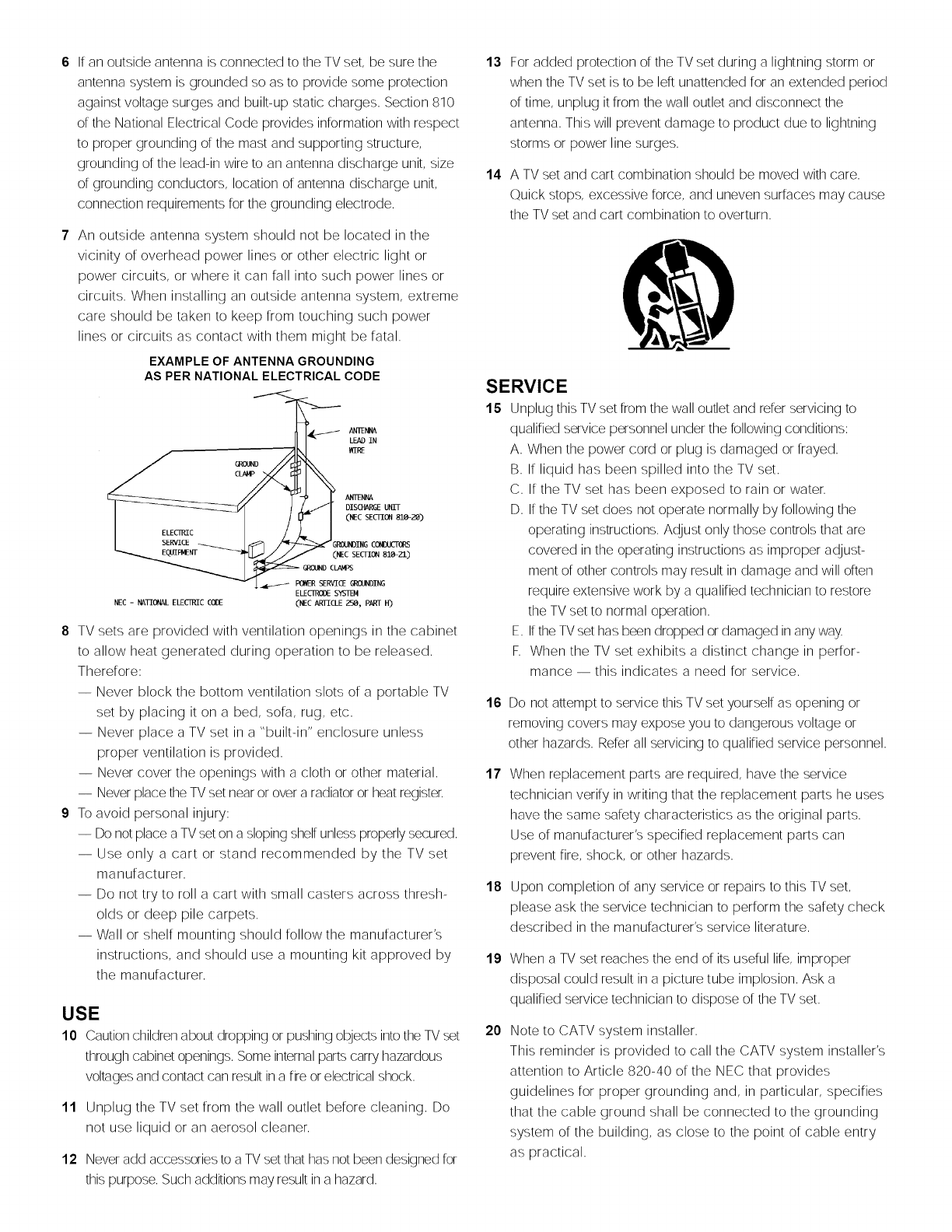
EXAMPLEOF ANTENNA GROUNDING
AS PER NATIONAL ELECTRICAL CODE
ANTEi_
LEAD IN
WIRE
ANI_NNA
DISCHARGEUNIT
(NEC SECTION 810-;_)
_OUNDING CONDUCTORS
(NEC SECTION 81_ZI)
NEC - lCCTIONAL ELECII_C COI)E ELECIR(X)ESYSTEM
(NEC ARTICLE _, PART H)
8 TV sets are provided with ventilation openings in the cabinet
to allow heat generated during operation to be released.
Therefore:
-- Never block the bottom ventilation slots of a portable TV
set by placing it on a bed, sofa, rug, etc.
-- Never place a TV set in a "built-in" enclosure unless
proper ventilation is provided.
-- Never cover the openings with a cloth or other material.
-- Never place the TV set near or over aradiator or heat register.
9 To avoid personal injury:
-- Do not place a TVset on a sloping shelf unless properly secured.
-- Use only a cart or stand recommended by the TV set
manufacturer.
-- Do not try to roll a cart with small casters across thresh-
olds or deep pile carpets.
-- Wall or shelf mounting should follow the manufacturer's
instructions, and should use a mounting kit approved by
the manufacturer.
USE
10 Caution children about dropping or pushing oL_ectsinto the TV set
through cabinet openings. Some internal parts carry hazardous
voltages and contact can result in a fire or electrical shock.
11 Unplug the TV set from the wall outlet before cleaning. Do
not use liquid or an aerosol cleaner.
12 Never add accessories to a TV set that has not been designed for
this purpose. Such additions may result in a hazard.
For added protection of the TV set during a lightning storm or
when the TV set is to be left unattended for an extended period
of time, unplug it from the wall outlet and disconnect the
antenna. This will prevent damage to product due to lightning
storms or power line surges.
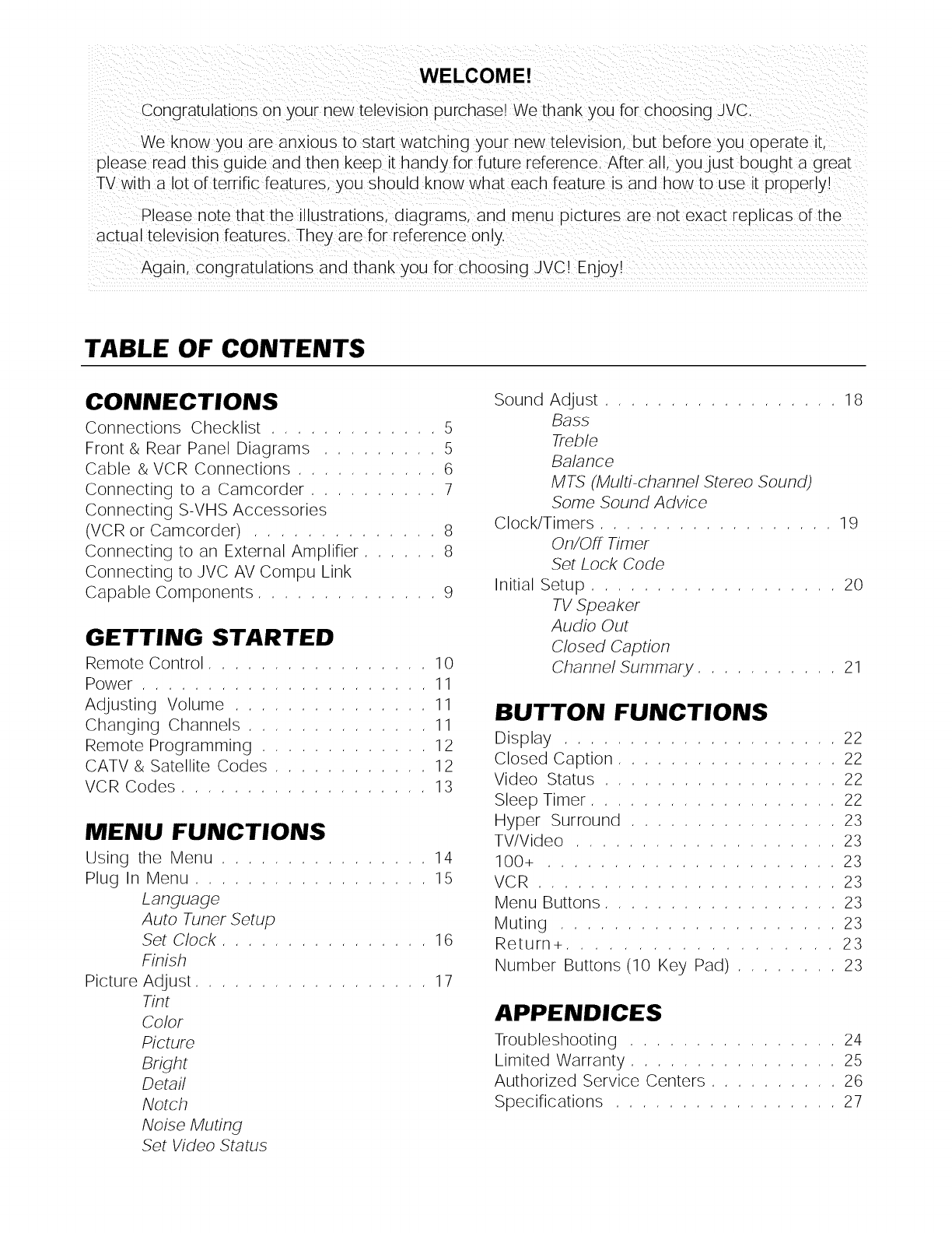
A TV set and cart combination should be moved with care.
Quick stops, excessive force, and uneven surfaces may cause
the TV set and cart combination to overturn.
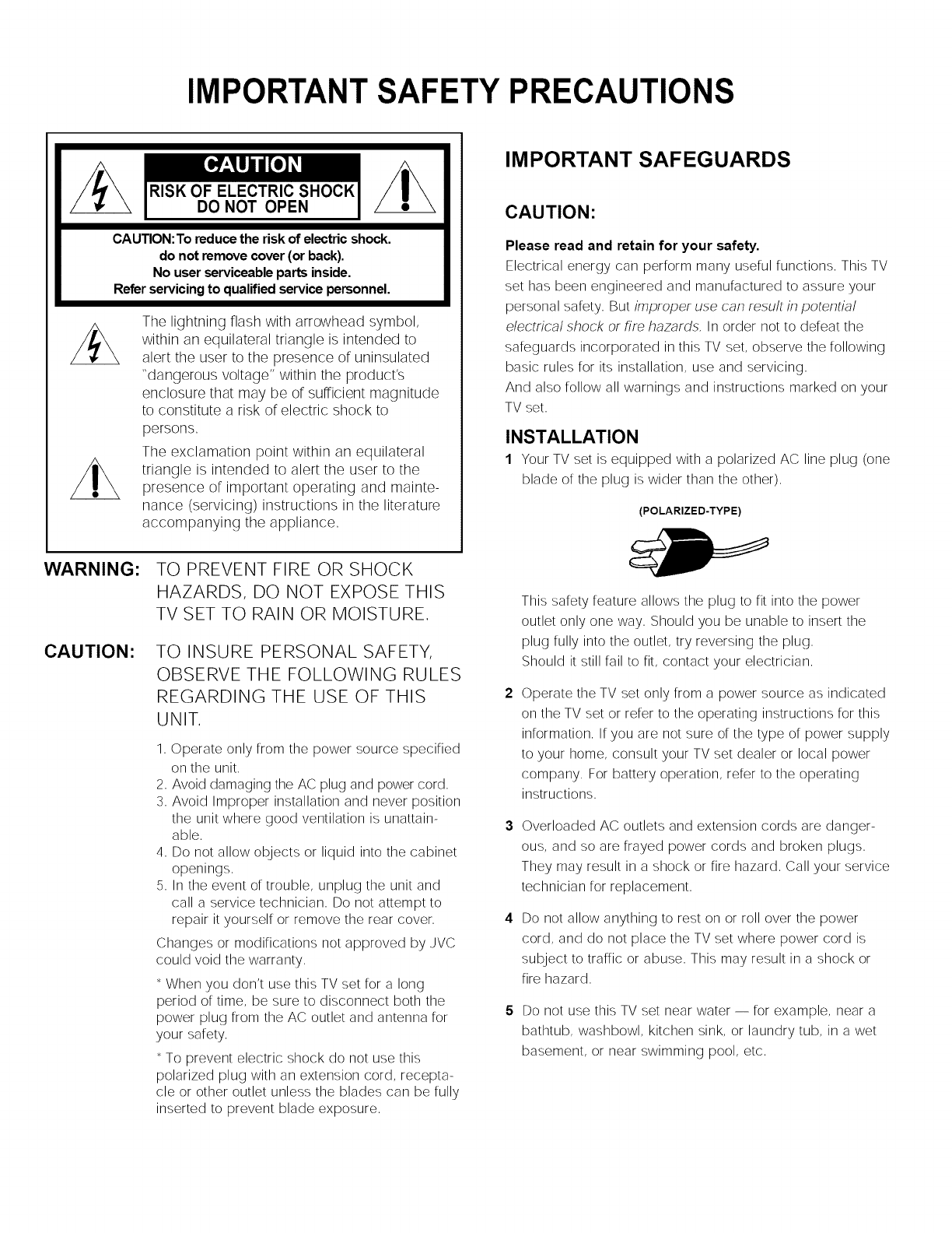
SERVICE
15 Unplug this TV set from the wall outlet and refer servicing to
qualified service personnel under the following conditions:
A. When the power cord or plug is damaged or frayed.
B. If liquid has been spilled into the TV set.
C. If the TV set has been exposed to rain or water.
D. Ifthe TV set does not operate normally by following the
operating instructions. Adjust only those controls that are
covered in the operating instructions as improper adjust-
ment of other controls may result in damage and will often
require extensive work by a qualified technician to restore
the TV set to normal operation.
E. Ifthe TV set has been dropped or damaged in any way.
F. When the TV set exhibits a distinct change in perfor-
mance -- this indicates a need for service.
16
17
18
Do not attempt to service this TV set yourself as opening or
removing covers may expose you to dangerous voltage or
other hazards. Refer all servicing to qualified service personnel.
When replacement parts are required, have the service
technician verify in writing that the replacement parts he uses
have the same safety characteristics as the original parts.
Use of manufacturer's specified replacement parts can
prevent fire, shock, or other hazards.
Upon completion of any service or repairs to this TV set,
please ask the service technician to perform the safety check
described in the manufacturer's service literature.
19
20
When a TV set reaches the end of its useful life, improper
disposal could result in a picture tube implosion. Ask a
qualified service technician to dispose of the TV set.
Note to CATV system installer.
This reminder is provided to call the CATV system installer's
attention to Article 820-40 of the NEC that provides
guidelines for proper grounding and, in particular, specifies
that the cable ground shall be connected to the grounding
system of the building, as close to the point of cable entry
as practical.
WELCOME!
Congratulations on your new television purchase! We thank you for choosing JVC
We know you are anxious to start watching your new television, but before you operate it.
please read this guide and then keep it handy for future reference. After all, you just bought a great
TV with a lot of terrific features, you should know what each feature is and how to use it properly!
Please note that the illustrations, diagrams, and menu pictures are not exact replicas of the
actual television features. They are for reference only.
Again. congratulations and thank you for choosing JVC! Enjoy!
TABLE OF CONTENTS
CONNECTIONS
Connections Checklist ............. 5
Front & Rear Panel Diagrams ......... 5
Cable & VCR Connections ........... 6
Connecting to a Camcorder .......... 7
Connecting S-VHS Accessories
(VCR or Camcorder) .............. 8
Connecting to an External Amplifier ...... 8
Connecting to JVC AV Compu Link
Capable Components .............. 9
GETTING STARTED
Remote Control ................. 10
Power ...................... 11
Adjusting Volume ............... 11
Changing Channels .............. 11
Remote Programming ............. 12
CATV & Satellite Codes ............ 12
VCR Codes ................... 13
MENU FUNCTIONS
Using the Menu ................ 14
Plug In Menu .................. 15
Language
Auto Tuner Setup
Set Clock ................ 16
Finish
Picture Adjust .................. 17
Tint
Color
Picture
Bright
Detail
Notch
Noise Muting
Set Video Status
Sound Adjust .................. 18
Bass
Treble
Balance
MTS (Multi-channel Stereo Sound)
Some Sound Advice
Clock/Timers .................. 19
On/Off Timer
Set Lock Code
Initial Setup ................... 20
TV Speaker
Audio Out
Closed Caption
Channel Summary ........... 21
BUTTON FUNCTIONS
Display ..................... 22
Closed Caption ................. 22
Video Status .................. 22
Sleep Timer ................... 22
Hyper Surround ................ 23
TV/Video .................... 23
100+ ...................... 23
VCR ....................... 23
Menu Buttons .................. 23
Muting ..................... 23
Return+ ................... 23
Number Buttons (10 Key Pad) ........ 23
APPENDICES
Troubleshooting ................ 24
Limited Warranty ................ 25
Authorized Service Centers .......... 26
Specifications ................. 27
CONNECTIONS
CONNECTIONS CHECKLIST READ ME FIRST!
The Connections Checklist Read Me First! SeCtion of this guide isa list of ideas t0 keep in mind
when you set out to perform y0ur connections, It is designed to he!p us n0t-so technicallyi
advanced individua!sl If y0 u read this seCti0n, and canlt identify the plugs C0nnect0rs, and
components you have, do not be afraid to seek help,
1) Always refer to the connection instructions in the user's
guide for .your components first! The manufacturer will
provide the most detailed information about their products,
2) Know your jacks and plugs -- most are color coded'
• Yellow plugs are Video connections
• Red plugs are Right Audio connections
• White or black plugs are Left Audio (Mono) connec-
tions (if.your VCR is mono, it will have a white or
black plug, no red)
3) Perform one hookup at a time. If you have many
accessories to connect, make sure each connection is
correct by checking to see that it works properly before
attempting the next connection,
4) Unplug the power cord between each connection.
5) In and Out Concept. Remember In and Out, The Output jack
from one piece will go to the Input jack of the other -- read the
jack panels, they are all labeled,
A/V input plug
RF Connectors
S-Video Plug
FRONT & REAR PANEL DIAGRAMS
REAR PANEL DIAGRAM FRONT PANEL DIAGRAM
CONNECTIONS
CABLE &VCR CONNECTIONS
There are two basic types of antenna or cable hookups. If you have an antenna, or have a cable TV
system that does not require you to use a cable box to tune channels, use Diagram #1. If you have a
cable system that requires you to use a cable box to access all channels, use Diagram #2. If you have
a cable system that requires you to use a cable box to access certain premium channels, but not
regular basic channels, use Diagram # 3.
NOTE: Toget stereo sound from ahi-fi stereo VCR.you must connect it to the TV withAudio/Video cables. Also to
get the best picture quality from any VCR use Audio/Video cables. (Use them! You'llbe glad you did.)
1) Connect cable or antenna 141-w_re outrrom tlae wall, in to tlqe spl_tter 141-_nput.
2) Connect RF wire Outfrom the splitter RF output, in to the VCR RF input.
3) Connect RF wire Outfrom the splitter RF output, in to the TV VHF/UHF input.
4) Connect yellow video cable outfrom the VCR Video output, in to the TV Video input jack.
5) Connect white audio cable outfrom the VCR LeR Audio output, in to the TV LeRAudio input jack.
6) Connect red audio cable outfrom the VCR Right Audio output, into the TV Right Audio inputjack.
[] If your VCR is mono it has only one audio outjack, connect it to TV L/Mono input.
1) Connect th(
2) Connect RF
3) Connect RF vvn_e uu_ ilc)rrl trl_ v_K Kr output, Ill to) trl_ I v vmr/umr iriput,
4) Connect yellow video cable outfrom the VCR Video output, in to the TV Video input jack.
5) Connect white audio cable outfrom the VCR LeE audio output, in to the TV LeRAudio input jack.
6) Connect red audio cable outfrom the VCR Right Audio output, into the TV Right Audio inputjack.
[] If your VCR is mono it has only one audio outjack, connect it to TV L/Mono input.
CONNECTIONS
CABLE &VCR CONNECTIONS CONTINUED
I)Conne( i i
2)Connect RF Outfrom splitterRF output,intocable box RF input,
3)Connect RF wireOutfrom cablebox RF output,intoVCR RF input,
4) Connect RF wire Outfrom splitter RF output, in to TV VHF/UHF input.
5) Connect yellow video cable outfrom VCR Video output, in to TV Video input jack.
6) Connect white audio cable outfrom VCR Left audio output, in to TV Left Audio input jack.
7) Connect red audio cable outfrom VCR Right Audio output, in to TV Right Audio inputjack.
[] If your VCR is mono it has only one audio outjack, connect it to TV L/Mono input.
CONNECTING TO A CAMCORDER
Connect acamcorder to your TV.
1) Connect white audio cable outfrom the camcorder plug, in to the TV LeftAudio inputjack.
2) Connect yellow video cable outfrom the camcorder plug, into the TVVideo inputjack.
3) If you have a stereo model camcorder, connect red audio cable out from the camcorder, into the TV Right Audio
inputjack.
[] Refer to the camcorder's instruction book for any special instructions.
CONNECTIONS
CONNECTING S-VHS ACCESSORIES (VCR or Carncorder)
Keeping the audio connections the same as for a non-S-VHS VCR or camcorder (page 7), use the special
S-VHS cable that came with the VCR or Camcorder. Illustration is of S-VHS VCR hookup.
1) Connect the S-VHS Plug outfrom VCR S-Video output, in to the TV's S-Video input.
[] Refer to your VCR or camcorder instructions.
CONNECTING TO AN EXTERNAL AMPLIFIER
Set the TV Speaker to OFF (page 20),switch the audio output to VARI (page 20), and adjust the sound with the
TVremote's VOLUME-/+button (page 77.)
1) Connect white audio cable outfrom the TV LeR Audio output jack in to the Amplifier [LeR] input.
2) Connect red audio cable outfrom the TV Right Audio output jack in to the Amplifier [Right] input.
[] Refer to the amplifier's instructions.
CONNECTIONS
CONNECTING TO JV'C AV' COMPULINK CAPABLE
COMPONENTS
AV Compu Link makes play ng video tapes totally automatic: Simply nsert a pre÷recorded tape* into
the VCR and the VCR automatically turns on and starts playing. At the same time the VCR sends an
AV Compu Link signal to the television telling it to turn on and switch to the correct video input:
NO TES:
1) The AV Compu Link cable has a Male 3.5 mm (mono) mini plug on each end.
2) If your JVC brand VCR has A Code/B Code Remote Control Switching (see VCR instructions), using
VCRA Code will switch the TV to Video Input 1. Using__BCode will switch the TV to Video Input 2.
3) To connect a JVC HiFi receiver or amplifier for a completely automated home theater, see the HiFi receiver's
instructions for detailed hookup diagrams.
In order for A V Compu Link to work, the recording tabs must be removed from the VHS tape.
_A V COMPU LINK EX is compatible with the following 7998 receivers: RX-664, RX-774, RX-884, and RX-7024
and later receiver models.
GETTING STARTED
REMOTE CONTROL
RM'C754
AV-32920
CHANGING THE REMOTE CONTROLOS BATTER-
IES
Use only size AA batteries,
nPush down on the remote's back cover and slide
... towards the bottom to remove it,
Insert the two supplied AA batteries, cardully noting
the "+" and "-" markings on the batteries and remote
_1 control,
To avoid a short circuit, insert "-" end first, Slide the cover
back into place (until it clicks into position),
[] If it takes more than three minutes to change the
batteries, you may have to reprogram the CA TV and/or
VCR codes (see page 72-73,)
[] If the remote control acts erratically, replace the batteries,
Battery life is usually six months to one year
[] We recommend the use of alkaline batteries for longer
battery life,