AV-21F9
No. 5603710
SERVICE ADJUSTMENTS
BEFORE STARTING SERVICE ADJUSTMENT
MEASURING INSTRUMENT
AND FIXTURES
1. DC voltmeter (or Digital voltmeter)
2. Oscilloscope
3. Signal generator (Pattern generator)
[PAL / SECAM / NTSC]
4. Remote control unit
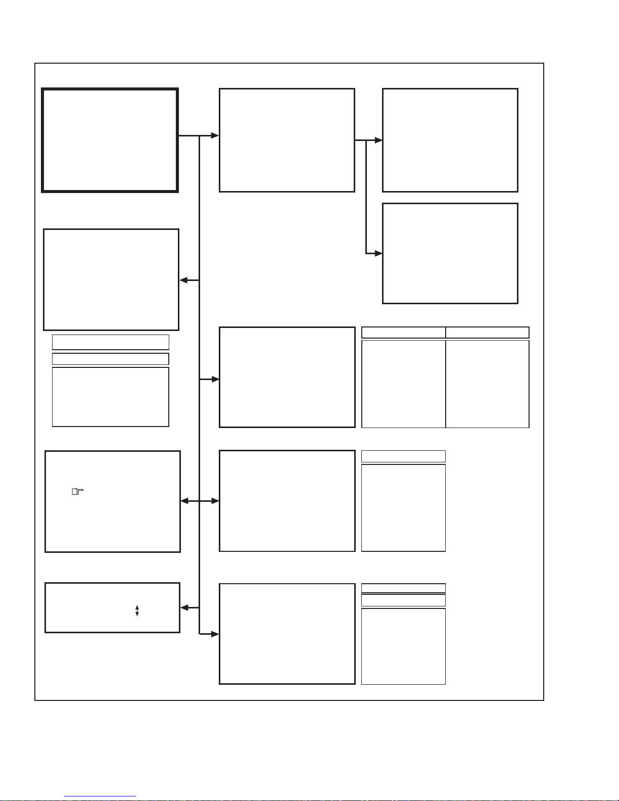
BASIC OPERATION IN SERVICE MENU
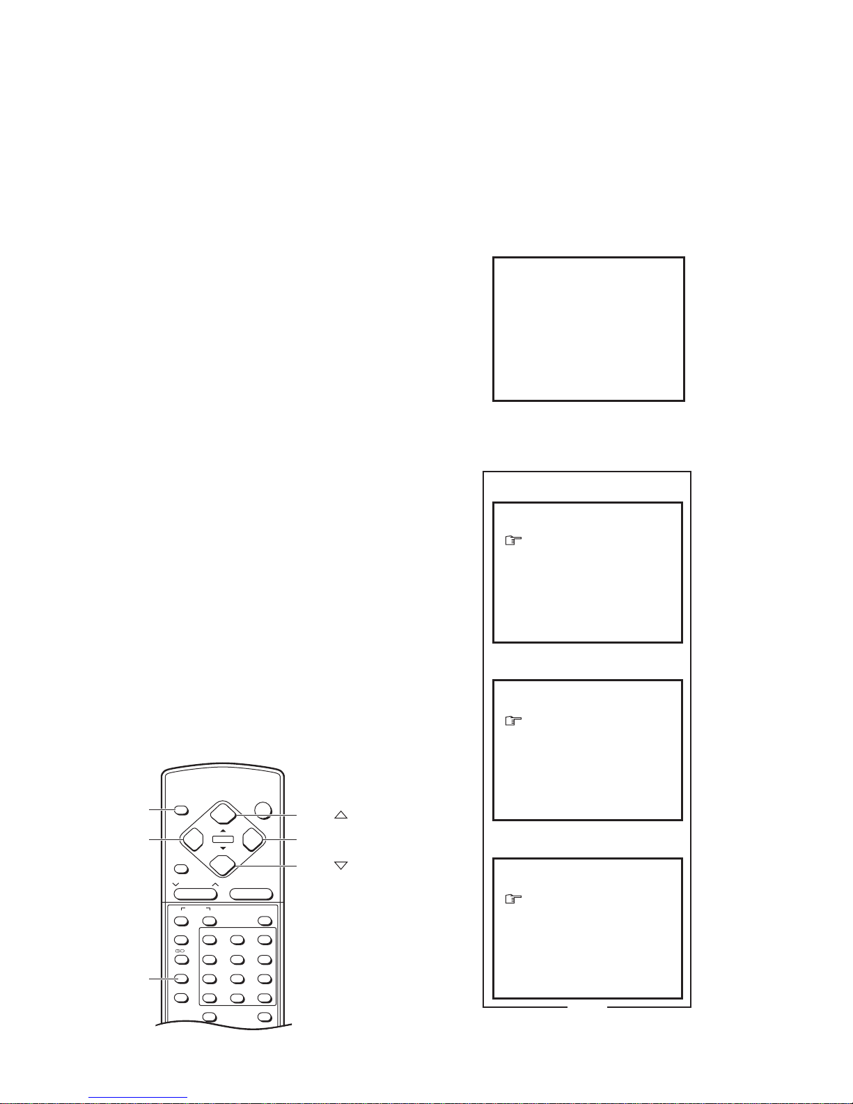
1. TOOL OF SERVICE MENU OPERATION
Operate the SERVICE MENU with the remote control unit.
2. SERVICE MENU ITEMS
With the SERVICE MENU, various settings (adjustments) can be made, and they are broadly classified in the following items of settings:
●1. IF ............................. For entering/adjusting the setting values (adjustment values) of the IF circuit.
●2. V/C........................... For entering/adjusting the setting values (adjustment values) of the VIDEO/CHROMA circuit.
●3. AUDIO ..................... For entering/adjusting the setting values (adjustment values) of the multiplicity sound circuit.
(Do not adjust the preset values.)
●4. DEF ......................... For entering/adjusting the setting values (adjustment values) of the DEFLECTION circuit.
●5. VSM PRESET ......... For setting the values of STANDARD, SOFT and BRIGHT (Do not adjust the preset values.)
(VSM: video status memory)
●6. CENTER.................. For setting the CENTER ADJUST values of TREBLE and BASS. (Do not adjust the preset values.)
●7. TURBO TIMER........ For quick setting the values of TIMER COUNT — adjustable not only by minutes but also by second. If it is ON,
the time in TIMER mode changes from 1 minute into 1 second temporarily. (Applicable to OFF TIMER, ON
TIMER and AUTO SHUTOFF)
Note: When you turn the TV power off, the Turbo Timer is automatically set to OFF.
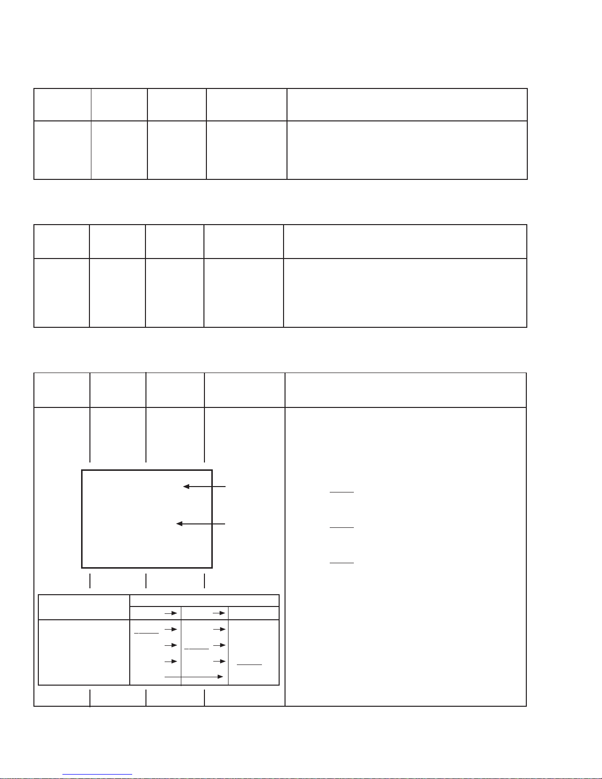
1. There are 2 ways for adjusting this TV: One is with the
REMOTE CONTROL UNIT and the other is the conventional
method using adjustment parts and components.
2. The setting (adjustment) using the REMOTE CONTROL
UNIT is made on the basis of the initial setting values. The
setting values which adjust the screen to the optimum con-
dition can be different from the initial setting values.
3. Make surethat connection iscorrectly made toACpowersource.
4. Turnon the powerof theTV and measuringinstrumentfor warm-
ing up for at least 30 minutes before starting adjustment.
5. If the receive or input signal is not specified, use the most ap-
propriate signal for adjustment.
6. Never touch parts (such as variable resistors, transformers and
capacitors) not shown in the adjustment items of this service
adjustment.
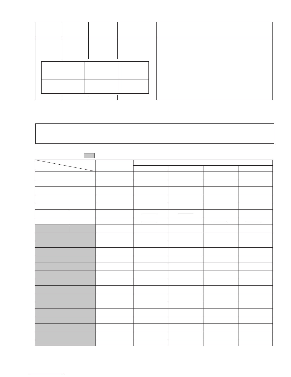
7. Preparation for adjustment (presetting):
Unless otherwise specified in the adjustment items, preset the
following functions with the remote control unit.
Function
PICTURE MODE (VSM)
COLOUR/BRIGHT/CONT./SHARP
VNR
TREBLE/BASS/BALANCE
LIVE SPATIAL
ECO SENSOR
Setting value
BRIGHT
See "VSM Preset"
on page 23.
OFF
CENTER
OFF
OFF
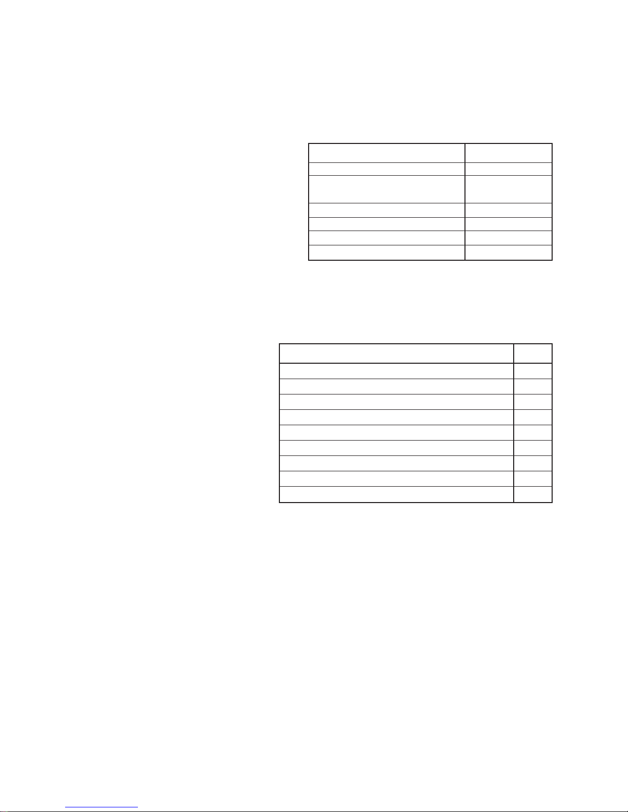
ADJUSTMENT/CHECK ITEMS
Adjustment/Check item Page
B1 POWER SUPPLY Check 14
FOCUS Adjustment 14
IF CIRCUITAdjustment 14
V/C (VIDEO/CHROMA) CIRCUITAdjustment 15
DEFLECTION CIRCUIT Adjustment 21
VSM PRESET Adjustment 23
AUDIO Adjustment 23
CENTER Adjustment 23
PURITY, CONVERGENCE Adjustment 24