JVC AV-36260 User manual

COLOR TELEVISION
USER'SGUIDE
F
ormod
e
l
s
:
AV-36260
AV-36230
AV-32260
AV-32230
AV-27260
Illustration ofAV-32260 and RM-C305
IMPORTANT NOTE TO THE CUSTOMER
In the space below, enter the serial number of your television (located at the rear
of the television cabinet). Staple your sales receipt or invoice to the inside cover
of this guide. Keep this user's guide in a convenient place for
future reference. Keep the carton and original packaging for future use.
SerialNumberModelNumber
LC T 09 51-0 01 B-A
0 30 1 -T N -JII-JIM
AC/Core line mini-IB 3/16/01 4:07 PM Page 1

IMPORTANT SAFETY PRECAUTIONS
WARNING: TO PREVENT FIRE OR SH O C K HAZARDS,D O N OT
EXPOSE THIS TV SET TO RAIN OR MOISTURE.
CAUTION: TO INSURE PERS O NAL SA FETY,O BSERVE THE
F OLL OWIN G RULES RE G ARDIN G THE USE O F
THIS UNIT.
1.O perate only from the powersource specified on the unit.
2.Avoid damaging the AC plug and powercord.
3.Avoid Improperinstallation and neverposition the unit where good
ventilation is unattainable.
4.Do notallow objects orliquid into the cabinetopenings.
5.In the eventoftrouble,unplug the unit and call a service technician.
Do notattemptto repairit yourself orremove the rearcover.
Changes ormodifications notapproved by JVC could void the warranty.
*When you don’t use this TV setfora long period oftime,be sure to
disconnectboth the powerplug from the A C outletand antenna for
yoursafety.
*To preventelectric shockdo notuse this polarized plug with an
extension cord,receptacle orotheroutletunless the blades can be
fully inserted to preventblade exposure.
CAUTION:To reduce the risk of electric shock.
Do not remove cover (or back).
No user serviceable parts inside.
Refer servicing to qualified service personnel.
The lightning flash with arrowhead symbol,
within an equilateral triangle is intended to alert
the user to the presence of uninsulated “dan-
gerous voltage” within the product’s enclosure
that may be of sufficient magnitude to consti-
tute a risk of electric shock to persons.
The exclamation point within an equilateral tri-
angle is intended to alert the user to the pres-
ence of important operating and maintenance
(servicing) instructions in the literature accom-
panying the appliance.
RISK OF ELECTRIC SHOCK
DO NOT OPEN
CAUTION
AC/Core line mini-IB 3/16/01 4:07 PM Page 2

IMPORTANT SAFEGUARDS
CAUTION:
Please read and retain for your safety.
Electricalenergy can perform many usefulfunctions.This TV sethas been engineered
and manufactured to assure yourpersonalsafety.But
improperuse can result in poten-
tialelectricalshockorfire hazards.
In ordernotto defeatthe safeguards incorporated in
this TV set,observe the following basic rules forits installation,use and servicing.
And also follow all warnings and instructions marked on yourTV set.
INSTALLATION
1YourTV setis equipped with a polariz ed A C line plug (one blade ofthe plug is wider
than the other).
This safety feature allows the plug to fit into the poweroutletonly one way.Should
you be unable to insertthe plug fully into the outlet,try reversing the plug.
Should it still fail to fit,contactyourelectrician.
2O perate the TV setonly from a powersource as indicated on the TV setorreferto the
operating instructions forthis information.If you are notsure ofthe type ofpower
supply to yourhome,consult yourTV setdealerorlocalpowercompany.Forbattery
operation,referto the operating instructions.
3Overloa ded A C outlets and extension cords are dangerous,and so are frayed power
cords and broken plugs.They may result in a shockorfire hazard.C all yourservice
technician forreplacement.
4Do notallow anything to reston orroll overthe powercord,and do notplace the TV
setwhere powercord is subjectto traffic orabuse.This may result in a shockorfire
hazard.
5Do notuse this TV setnearwater—forexample,neara bathtub,washbowl,kitchen
sink,orlaundry tub,in a wetbasement,ornearswimming pool,etc.
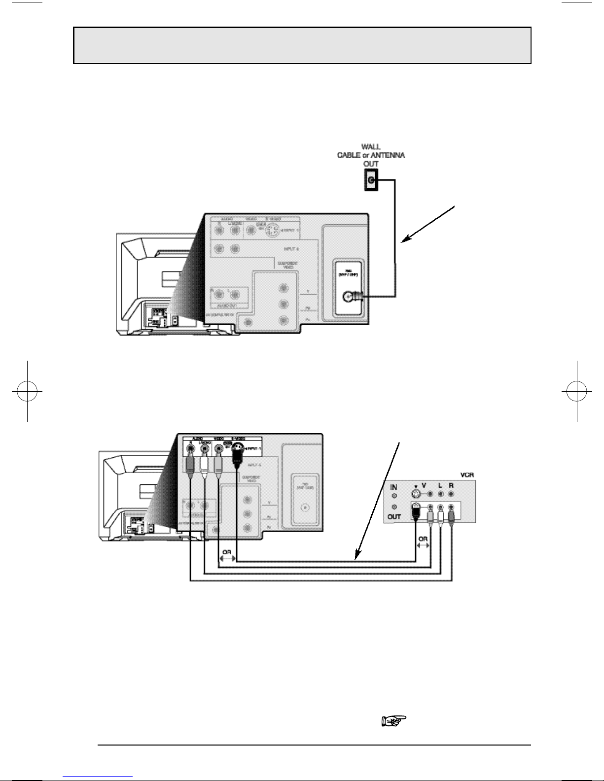
6If an outside antenna is connected to the TV set,be sure the antenna system is
grounded so as to provide some protection againstvoltage surges and built-up static
charges.Section 810 ofthe NationalElectricalCode provides information with
respectto propergrounding ofthe mastand supporting structure,grounding ofthe
lead-in wire to an antenna discharge unit,size ofgrounding conductors,location of
antenna discharge unit,connection requirements forthe grounding electrode.
(POLARIZED-TYPE)
AC/Core line mini-IB 3/16/01 4:07 PM Page 3

7An outside antenna system should notbe located in the vicinity ofoverhead power
lines orotherelectric lightorpowercircuits,orwhere it can fall into such powerlines
orcircuits.When installing an outside antenna system,extreme care should be taken
to keep from touching such powerlines orcircuits as contactwith them mightbe
fatal.
8TV sets are provided with ventilation openings in the cabinetto allow heatgenerated
during operation to be released.
Therefore:
—Neverblockthe bottom ventilation slots ofa portable TV setby placing it on a
bed,sofa,rug,etc.
—Neverplace a TV setin a “built-in”enclosure unless properventilation is provided.
—Nevercoverthe openings with a cloth orothermaterial.
—Neverplace the TV setnearorovera radiatororheatregister.
9To avoid personalinjury:
—Do notplace a TV seton a sloping shelf unless properly secured.
—Use only a c artorstand re comme nd e d b y the TV setmanufa cturer.
—Do nottry to roll a cartwith small casters across thresholds ordeep pile carpets.
—Wall orshelf mounting should follow the manufacturer’s instructions,and should
use a mounting kit approved by the manufacturer.
USE
10 Caution children aboutdropping orpushing objects into the TV setthrough cabinetopenings.
Some internalparts carry hazardous voltages and contactcan result in a fire orelectricalshock.
11 Unplug the TV setfrom the wall outletbefore cleaning.Do notuse liquid oran
aerosolcleaner.
12 Neveradd accessories to a TV setthathas notbeen designed forthis purpose.
Such additions may result in a hazard.
EXAMPLE OF ANTENNA GROUNDING
AS PER NATIONAL ELECTRICAL CODE
AC/Core line mini-IB 3/16/01 4:07 PM Page 4

13 Foradded protection ofthe TV setduring a lightning storm orwhen the TV setis to be left
unattended foran extended period oftime,unplug it from the wall outletand disconnect
the antenna.This will preventdamage to productdue to lightning storms orpowerline
surges.
14 A TV setand cartcombination should be moved with
care.Quickstops,excessive force,and uneven sur-
faces may cause the TV setand cartcombination to
overturn.
SERVICE
15 Unplug this TV setfrom the wall outletand referservicing to qualified service per-
sonnelunderthe following conditions:
A.When the powercord orplug is damaged orfrayed.
B.If liquid has been spilled into the TV set.
C.If the TV sethas been exposed to rain orwater.
D.If the TV setdoes notoperate normally by following the operating instructions.
Adjustonly those controls thatare covered in the operating instructions as
improperadjustmentofothercontrols may result in damage and will often require
extensive workby a qualified technician to restore the TV setto normaloperation.
E.If the TV sethas been dropped ordamaged in any way.
F.When the TV setexhibits a distinctchange in performance —this indicates a
need forservice.
16 Do notattemptto service this TV setyourself as opening orremoving covers may
expose you to dangerous voltage orotherhazards.Referall servicing to qualified
service personnel.
17 When replacementparts are required,have the service technician verify in writing
thatthe replacementparts he uses have the same safety characteristics as the orig-
inalparts.Use ofmanufacturer’s specified replacementparts can preventfire,
shock,orotherhazards.
18 Upon completion ofany service orrepairs to this TV set,please askthe service techni-
cian to perform the safety checkdescribed in the manufacturer’s service literature.
19 When a TV setreaches the end ofits usefullife,improperdisposalcould result in a pic-
ture tube implosion.Aska qualified service technician to dispose ofthe TV set.
20 Note to C ATV system installer.
This reminderis provided to call the C ATV system installer’s attention to Article 820-
40 ofthe N E C thatprovides guidelines forpropergrounding and,in particular,spec-
ifies thatthe cable ground shall be connected to the grounding system ofthe build-
ing,as close to the pointofcable entry as practical.
AC/Core line mini-IB 3/16/01 4:07 PM Page 5

R M -C 30 5
Two AA
Batteries
AV-32260
1 Television
1 R em ote
C ontrol
Thank you for your purchase of a JV C Color Television. Before you begin setting up your new television,
please check to make sure you have all of the following items. In addition to this guide, your television
box should include:
O nce you have unpacked your television, the next step is to connect it to your antenna, cable or
satellite system and to connect the audio/video devices you want to use with your television. To
make these connections you will use plugs like the ones illustrated below.
A/V Input Plug
RF Connectors
U sed to connect a
coaxial cable from an
external antenna or
C able T V system .
A matching TV stand
is also available (sold
separately).
U sed to m ake video
connections with
som e VC R s, D V D s,
C am corde rs, etc.
U sed to connect
audio/video devices like
V C R s, D V D players,
stereo amplifiers, game
consoles, etc.
S-Video Plug
We recommend that before you start using your new television, you read this entire User’s Guide so
you can learn about your new television’s many great features. But if you’re anxious to start using
your television right away, a quick setup guide follows on the next three pages.
Unpacking Your Television
6
Used to connect JVC AV
Compu Link capable
components for an
automated home theater.
AV Compu Link Cable
Note: Your television
and/or remote control
may differ from the
examples illustrated
here.
AC/Core line mini-IB 3/16/01 4:07 PM Page 6

7
Slide the cover on the back of the remote down towards the bottom of the remote control. Insert two
batteries carefully noting the “+” and “– ” markings, placing the “–” end in the unit first. S lide the
cover back into place.
Getting Started
Step One - The Remote Control
The remote control is the ke y to operating your television's ma ny great fea tures. Before you can
operate your remote control, you first need to install the batteries (included).
Basic Operation
Turn the television on and off by pressing the PO W E R button at the top right corner of the remote.
The four key fea ture buttons at the center of the remote can be used for basic opera tion of the
television. The top and bottom buttons will scan forward and back through the available channels.
The right and left buttons will turn the volume up or down. These buttons are also marked with four
arrows and are also used with JVC 's onscreen menu system . You will need to use these buttons
later in the Quick S etup Section.
The next step is to conne ct your television to an antenna or cable.
Remote Power
Button
Remote Key Feature Buttons
Proceed to S tep Two
These quick setup pages will provide you, in three easy steps, with the basic information you need
to begin using your new television right away. This inform ation includes basic instructions on
operating your remote control, making a simple cable/antenna and optional VC R connection and,
finally, information on programming your television's Auto Tuner.
If you have questions, or for more detailed information on any of these steps, please consult other
sections of this guide.
Quick Setup 1
AC/Core line mini-IB 3/16/01 4:07 PM Page 7

C able/R F conne ctor
8
AV C ables/P lugs
Step Two - Making Basic Connections
N ext you will need to connect your television to an antenna or cable syste m. The m ost basic
antenna /cable connection is shown below. For more deta iled connections, such as ones where a
cable box is required, see pa ges 11 to 13 .
You may also wish to connect a VC R at this point. Abasic VC R connection is shown below. For
detailed instructions on connecting other components or a home theater system, see pages 14 to 16.
Note: A V CR is not required to operate your television.
1) C onnect the yellow video cable out from the VC R ’s Video O utput, in to the TV’s Video Input
jack, OR connect a n S-V ideo cable from the V C R ’s S -Video O utput, to the TV ’s S-V ide o Input.
2) C onnect the white audio cable out from the VC R ’s Left Audio O utput, in to the TV ’s Left Audio
Input jack.
3) C onne ct the red a udio ca ble out from the V C R ’s R ight Audio O utput, in to the TV ’s R ight
Audio Input jack.
Finally, once you have finished your connections, plug the power cord into the nearest power outlet
and turn on the television.
1) C onnect an R F cable out from the wall outlet in to the R FInput on the back of the TV.
Proceed to S tep Three
Quick Setup 2
AC/Core line mini-IB 3/16/01 4:07 PM Page 8

9
P ress the buttons to m ove to AU T O T U N ER S E T U P
P ress the buttons to be gin AU TO T U N E R SE T U P
To choose C ABLE (if you are connected to a cable system) or AIR (if you use
an antenna)
To m ove to ST ART
To start Auto Tuner S etup
The Auto Tuner will now mem orize all of the clear, active channels your television can
receive. This will take one or two minutes.
N
O
W
P
R
O
G
R
A
MM
I
N
G
!
48
T
U
N
E
R
M
OD
E
:
C
A
B
L
E
A
I
R
S
T
A
R
T
Step Three - The Plug In Menu
W hen you turn your television on for the first time the Plug In M enu will appear. This menu sets
some of the basic settings for your television. A complete description of the Plug In M enu can be
found starting on page 22. W e recommend you com plete the P lug In M enu items before you start
using your television. But to begin watching your television right away you only need to run the Auto
Tuner S etup. T his lets your television learn the channels it is able to receive. To run the Auto Tuner
S etup follow the steps below .
T he Auto T une r is finished when the message P R O G R AM M IN G O V E R ! appe ars onscreen.
Your Q uick Setup is now complete. You can now begin watching your television, or you can continue on
in this guide for more information on connecting audio/video devices, programming your remote control,
or using the JVC onscreen menu system to customize your television viewing experience.
P
L
U
G
I
N
M
E
N
U
L
A
N
G
U
A
G
E E
N
G
F
R
E
S
P
A
A
U
T
O
T
U
N
E
R
S
E
T
U
P
S
E
T
C
L
O
C
K
F
I
N
I
S
H
S
E
L
E
C
T
B
Y
O
P
E
R
A
T
E
B
Y
E
X
I
T
B
Y
E
X
I
T
The Q uick S etup
is complete
Quick Setup 3
AC/Core line mini-IB 3/16/01 4:07 PM Page 9

Table of Contents
Quick Setup Guide ....7
CONNECTIONS
C able and VCR Connections .......11
Connecting to a DVD Player.......14
Connecting to an ExternalAmplifier...15
Connecting to a C amcorder.......15
Connecting to JVC AV Compu Link...16
GETTING STARTED
Remote Control
Remote ControlBasics
.....17
Changing the Batteries
.....17
Remote Programming ..........18
C ATV and Satellite Codes.........18
VCR Codes ................19
DVD Codes ................20
MENU FUNCTIONS
Using the Guide .............21
Plug In Menu
Introduction
..........22
La ngu a g e
...........22
Auto TunerSetup
.......22
Auto ClockSet
.........23
ManualClockSet
.......24
Finish
..............24
C ha nnelSummary............25
V-Chip...................26
SetLockCode
.........33
Picture Settings
Tint
...............34
Color
..............34
Picture
.........34
Bright
.............34
D etail
.............34
Noise Muting
.........35
SetVideo Status
........35
Sound Settings
Bass
..............36
Tre ble
.............36
B alance
............36
MTS (Multi-channelSound)
..36
G eneralItems
On/Off Timer
..........37
TV S peaker
..........38
Closed C a ption
........39
BUTTON FUNCTIONS
Menu...................40
Exit and PIP Off..............40
Display ..................40
Video Status ...............41
Sleep Timer................41
HyperSurround .............41
Muting ..................41
100+ ...................42
Return+..................42
Input...................42
VCR Buttons ...............43
DVD Buttons ...............43
TV/C ATV Switch .............43
VCR/DVD Switch .............43
PIP (Picture-In-Picture)
Introdu ction
..........44
On/Move
............44
Fre e z e
.............45
Swap
..............45
C ha nnel+ /-
..........45
Sourc e
.............45
APPENDICES
Troubleshooting .............46
Warr anty .................47
Authorized Servic e C enters .......49
Search Codes...............50
Specifications...............51
AC/Core line mini-IB 3/16/01 4:07 PM Page 10

1) Connect the antenna or cable TV wire from the wall outlet, in to the RFInput of the two-way splitter.
2) C onne ct a n R F cable from the one of the R F O utputs on the splitte r, in to the R F Input on the
back of the V C R .
3) C onnect an R F cable from the other the R F O utput on the splitter, in to the R F Input on the
back of the TV.
4) C onnect the yellow video cable out from the VC R ’s Video O utput, in to the TV’s Video Input
jack, OR connect an S-V ideo cable from the VC R ’s S-V ideo output, to the TV’s S-V ideo input.
5) C onnect the white audio cable out from the VC R ’s Left Audio O utput, in to the TV ’s Left Audio
Input Jack.
6) C onne ct the red a udio ca ble out from the V C R ’s R ight Audio O utput, in to the TV ’s R ight
Audio Input jack.
• If your VC R is a m ono sound unit, it will have only one Audio O ut jack. C onnect it to the TV’s
Left Audio Input.
• P lea se consult your V C R ’s owner ’s m anua l for more inform ation on its ope ration.
Connections
11
There are three basic types of antenna or cable connections:
• If you have an antenna or have a cable system that does not require you use a cable box to
se lect cha nne ls, ple ase re fer to D iagra m #1 .
• If you have a cable system that requires the use of a cable box to access all the channe ls,
please refer to D iagram #2. If you cannot operate your Picture-In-P icture function using D iagram
#2, try the connection shown in D iagram #3. It is possible your cable box allows the signal of only
one channel at a time to be sent to your television.
• If you have a cable system that requires the use of a cable box to access certa in premium
channels, but not “basic” cable cha nnels, please refer to D iagram #3.
• For your convenience, connection to a VC R is also shown in the following diagrams. A VCR is
not necessary for operation of the television or Picture-In-Picture (PIP) function. You ma y omit the
V C R from your connections if you wish.
• For instructions on connecting a VCR only, please see the Q uick S etup on page 8.
• For information on using PIP , please see page 44.
•The PIP feature is available on models AV-36260, AV-32260 and AV-27260 only.
Cable and VCR Connections
D iagram # 1
AC/Core line mini-IB 3/16/01 4:07 PM Page 11

Connections
12
1) Connect the antenna or cable TV wire from the wall outlet, in to the RFInput of the cable box.
2) C onne ct a n R F cable from the R F O utput of the cable box, in to the R F Input on the ba ck of
the V C R .
3) C onne ct a n R F cable from the R F O utput of the V C R , in to the R FInput on the back of the TV.
4) C onnect the yellow video cable out from the VC R ’s Video O utput, in to the TV’s V ideo Input
jack, OR connect an S-V ideo cable from the VC R ’s S-V ideo output, to the TV’s S-V ideo input.
5) C onnect the white audio cable out from the VCR ’s Left Audio O utput, in to the TV ’s Left Audio
Input Jack.
6) C onne ct the red audio ca ble out from the V C R ’s R ightAudio O utput, in to the T V’s R ight
Audio Input jack.
• Please see page 44 for information on using the P IP feature with a C able Box.
• If your VC R is a m ono sound unit, it will have only one Audio O ut jack. C onnect it to the TV ’s
Left Audio Input.
• P lea se consult your V C R ’s owner ’s m anua l for more inform ation on its ope ration.
Cable and VCR Connections - Continued
D iagram # 2
AC/Core line mini-IB 3/16/01 4:07 PM Page 12

Connections
13
The connection diagrams are intended to show some basic general connections.Some
cable companies may require special connections to properly use your television or
2-tuner PIP function.If you follow these diagrams and either the television or PIP does not
work properly, contact your local cable operator for more connection information. Please
see page 44 for more information on the PIP feature.
Cable and VCR Connections - Continued
1) Connect the antenna or cable TV wire from the wall outlet, in to the R FInput of the two-way splitter.
2) C onnect an R Fcable from the one of the RFO utputs on the splitter, in to the cable box RF Input.
3) C onnect a n R Fca ble from the C a ble Box O utput, in to the V C R R F Input.
4) C onnect an R Fcable from the other the R FO utput on the splitter, in to the R F Input on the back of
the TV.
5) Connect the yellow video cable out from the VCR ’s Video O utput, in to the TV’s Video Input jack, OR
connect an S-Video cable from the VC R ’s S-V ideo output, to the TV’s S-V ideo input.
6) Connect the white audio cable out from the VC R ’s Left Audio O utput, in to the TV’s Left Audio Input
jack.
7) Connect the red audio cable out from the V CR ’s RightAudio Output, in to the TV’s Right Audio Input
jack.
• Please see page 44 for information on using the P IP feature with a C able Box.
• If your V C R is a mono sound unit, it will have only one Audio O ut jack. C onnect it to the TV ’s
Left Audio Input.
• P lea se consult your V C R ’s owner ’s m anua l for more inform ation on its ope ration.
D iagram # 3
AC/Core line mini-IB 3/16/01 4:07 PM Page 13

Connections
14
Connecting to a DVD player
1) C onnect G reen cable out from D VD player “Y ”C omponent Output, in to T V “Y ” Component Input.
2) C onnect Blue cable out from DV Dplayer “PB”C om ponent O utput, in to T V “P B”C omponent Input.
3) C onnect R ed cable out from DV DPlayer “PR”C om pone nt O utput, in to T V “P R” Component Input.
4) C onnect W hite Audio cable out from DVD Left Audio O utput, in to TV Left Audio Input 2.
5) Connect Red Audio cable out from DVDRight Audio Output, in to TV Right Audio Input 2.
• Green, blue and red are the most common colors for DVD cables. Some models may vary colors,
please consult the user’s manual for your D VDPlayer for more information.
• Be careful not to confuse the red D VDcable with the red audio cable. It is best to complete one set
of connections (DVD or Audio Output) before starting the other to avoid accidentally switching the
cables.
• See page 20 for instructions on programming your remote control to operate the basic functions of
your DVD player.
•NOTE: Progressive DVD Players (players with an output scan of 31.5 KHz) will not work properly
with this television.
AC/Core line mini-IB 3/16/01 4:07 PM Page 14

Connections
15
1) C onnect the yellow video cable out from the Cam corder’s V ideo O utput, in to the TV ’s Video
Input jack.
2) C onnect the white audio cable out from the C amcorder’s Left Audio O utput, in to the TV ’s Left
Audio Input jack.
3) C onne ct the red a udio ca ble out from the C am corde r’s R ight Audio O utput, in to the T V ’s R ight
Audio Input jack.
• If your C amcorder is a mono sound model it will have only one audio jack. C onnect it to the
TV ’s Left Audio jack.
• The front Input jacks (Input 3) of models AV-3626 0 and AV-36230 are located under the front
panel door.
Connecting to a Camcorder
You m ay connect a camcorder to your television by using the front input jacks (Input 3).You ma y
also connect a gam e console or other equipment using these jacks. C amcorders and game
consoles may also be connected to the television’s rear input jacks.
Connecting to an External Amplifier
1) Connect the white audio cable from the TV’s Left Audio Output jack to the Amplifier’s Left Audio Input jack.
2) Connect the red audio cable from the TV’s Right Audio Output jack to the Amplifier’s Right Audio Input jack.
• Also see “TV Speaker” on page 38 for more information on using external speakers.
Illustration of AV-32260
AC/Core line mini-IB 3/16/01 4:07 PM Page 15

Connections
16
To Connect: Plug one end of the AV Compu Link cable into the AV Compu Link EX input on your VC R,
DV D, or other C ompu Link device. P lug the other end of the AV Compu Link EX cable into the AV
Compu Link input at the rear of the television.
Connecting to JVC AV Compu Link
JV C ’sA V C ompu Link EX feature makes playing video tapes or DVD s totally automatic. Sim ply
insert a pre-re corded ta pe * into your AV C ompu Link E X com patible JV C -bra nd V C R or D V D into
your JV C DV D player and the device will automatica lly turn on and be gin playback. At the same
time, using the AV C om pu Link, the V C R or D V D playe rse nds a signal to the television telling it
to turn on and switch to the proper video input.
• The AV C om pu Link cable may be included with the JV C AV C ompu Link accessory you wish to
connect. If it is not, contact an authorized JVC Se rvice C enter for part # EW P 805-012.
•AV C om pu Link can only be used with JV C -brand products.
NOTES:
* In order for the VCR playback to begin automatically, the recording tab must be removed from the
VHStape. If the tab is in place, automatic switching will occur when you push the VCR’s PLAY button.
• The AV Compu Link cable has a male 3.5 mm (mono) plug on each end.
• If your JVC-brand VCR has “A Code/B Code Remote Control Switching” (see your VCR’s user’s guide),
using VCR A Code will switch the TV to input 1.
• To connect a JVC HiFi receiver or amplifier for a completely automated home theater, see the HiFi’s
connection instructions in its user’s guide for detailed connection information.
• AV COMPU LINK EX is compatible with the following receivers:RX-664V, RX-665V, RX-668VBK,
RX-774V, RX-778VBK, RX-884V, RX-888VBK, RX-1024V, RX-1028VBK, and later receiver models.
AC/Core line mini-IB 3/16/01 4:07 PM Page 16

Before you can operate the remote control, you must first install
the batteries (included). See “Changing the Batteries” at the
bottom of this page for instructions. (For an illustration, please see
page 7.)
Press the PO W E R button to turn the television on or off.
M ake sure the T V/C AT V switch is set to TV. M ove the switch to
C ATV only if you nee d to operate a cable box.
S lide the V C R /D V D se lector switch to V C R to control a V C R ,
slide to D VD to control a D V D player. P lea se se e pages 18 to
20 for instructions on programming your remote control to
ope rate a C able box, V C R or D V D pla ye r.
P ress the C H + and C H - buttons to sca n through the cha nne ls.
Ta p the C H + or C H - button to m ove through the cha nnels one
channel at a time.
To move rapidly through the channels using JV C ’s Hyperscan
fea ture, pre ss a nd hold C H + or C H -. T he cha nne ls will zip by a t
a rate of five channels per second.
Press V OL+ or VOL - to raise or lower the volume. An indicator
bar will appear onscreen to show you the television volum e
level.
T he C H + /- a nd V OL+/- buttons are also used to navigate JV C ’s
onscre en menu system .
You can directly access specific channels using the 10-key pad.
For more information on remote control button features, see
pages 40 to 45. For information on using the onscreen menus,
see page 21.
Changing the Batteries
Push down on the remote’s back cover and slide towards the bottom to rem ove it.
Insert two AAba tteries (supplied), carefully noting the "+" a nd "-" markings on the batteries and on
the remote control. To avoid a potential short circuit, insert the "-" end first. Be sure to use only size
AA batteries.
W hen batteries are installed, slide the cover back into place (until it clicks into position).
• If the remote control acts erratically, replace the batteries. Typical battery life is six months to one
year. W e recommend using alkaline batteries for longer battery life.
When you change the batteries, try to complete the task within three minutes. If you take longer than three
minutes, the remote control codes for your VCR, DVD, and/or Cable Box may have to be reset (see page 18-20).
RM-C305
Remote Control
17
Remote Control Basics
•
•
•
•
•
•
•
•
•
•
Notes: R em ote control m odel R M -C 3 05 is shown a t the le ft.
A different model remote control may have come with your
television.
AC/Core line mini-IB 3/16/01 4:07 PM Page 17

Remote Programming
18
Setting the CATV, VCR and DVD Codes
You can program your remote to operate your cable box, satellite receiver, V C R or D V D
player by using the instructions and codes listed below. If the equipment does not respond to any
of the codes listed below or to the code search function, use the remote control supplied by the
manufacturer.
Cable Box or Satellite setup
The remote control is programmed with C AT V and/or S atellite codes for power on, power off,
channel up, cha nnel down, and 10 key operation.
1) Find the C AT V/S atellite brand from the list of codes shown below.
2) Slide the 2-way selector switch to “C ATV ”.
3) P ress and hold down the D ISP LAY button.
4) W ith the DIS P LAY button held down, enter the first code number listed using the 10 key pa d.
5) R e lea se the D ISP LAY button.
6) C onfirm the operation of the C able Box/S atellite receiver.
• If your C ATV or S atellite box does not respond to the first code, try the others listed. If it does not
respond to any code, try the S earch C odes Function, on page 50.
AC/Core line mini-IB 3/16/01 4:07 PM Page 18

Remote Programming
VCR setup
The remote control is programm ed with VC R codes for power on, power off, play, stop, fast-forward,
rewind, pause, record, channel up, and channel down operation.
1) F ind the VC R brand from the list of codes shown below.
2) S lide the first 2 -way selector switch to “TV ” and the other 2-way selector switch to “V CR”.
3) P ress and hold down the D ISP LAY button.
4) W ith the DIS P LAY button held down, enter the first code number listed with the 10 key pa d.
5) R e lea se the D ISP LAY button.
6) C onfirm the ope ration of the V C R .
• If your V C R does not respond to the first code, try the others listed. If it does not respond to a ny
code, try the S earch C odes Function, on page 50 .
• Some manufacturer’s VCR’s may not respond to the TV/VCR button, even if other buttons work properly.
• To re cord, hold down the REC button on the rem ote and press P LAY.
19
AC/Core line mini-IB 3/16/01 4:07 PM Page 19

Remote Programming
20
The remote control is programm ed with D VD codes for power on, power off, play, stop,
fast-forward, rewind, previous chapter, next chapter, tray open/close, and still/pause operation.
1) F ind the D V D player brand from the list of code s shown below.
2) S lide the first 2 -way selector switch to “TV ” and the other 2-way selector switch to “D VD”.
3) P ress and hold down the D ISP LAY button.
4) W ith the D IS P LAY button held down, enter the first code number listed with the 10 key pad.
5) R e lea se the D IS PLAY button.
6) C onfirm the ope ration of the D V D playe r.
• If your DV D player does not respond to the first code, try the others listed. If it does not respond
to any code, try the Search C odes F unction, on page 5 0.
• After you program your remote, some D V D buttons may not work properly. If some buttons do not
work properly, use the remote control which came with your D VD player.
DVD setup
AC/Core line mini-IB 3/16/01 4:07 PM Page 20
Other manuals for AV-36260
2
This manual suits for next models
4
Table of contents
Other JVC TV manuals

JVC
JVC LT-65VU3105 User manual

JVC
JVC AV-32WL1EU User manual

JVC
JVC AV-14FN14 User manual

JVC
JVC AV-27D303/S User manual

JVC
JVC AV-21BF11ENS User manual

JVC
JVC AV-48WP30 User manual

JVC
JVC AV-29ED5BN, AV-29ED5SN User manual

JVC
JVC AV-20N8(BK) User manual

JVC
JVC GGT0118-001A-H User manual

JVC
JVC AV-28Z25 User manual