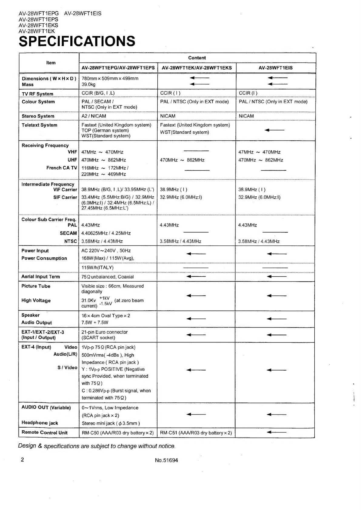
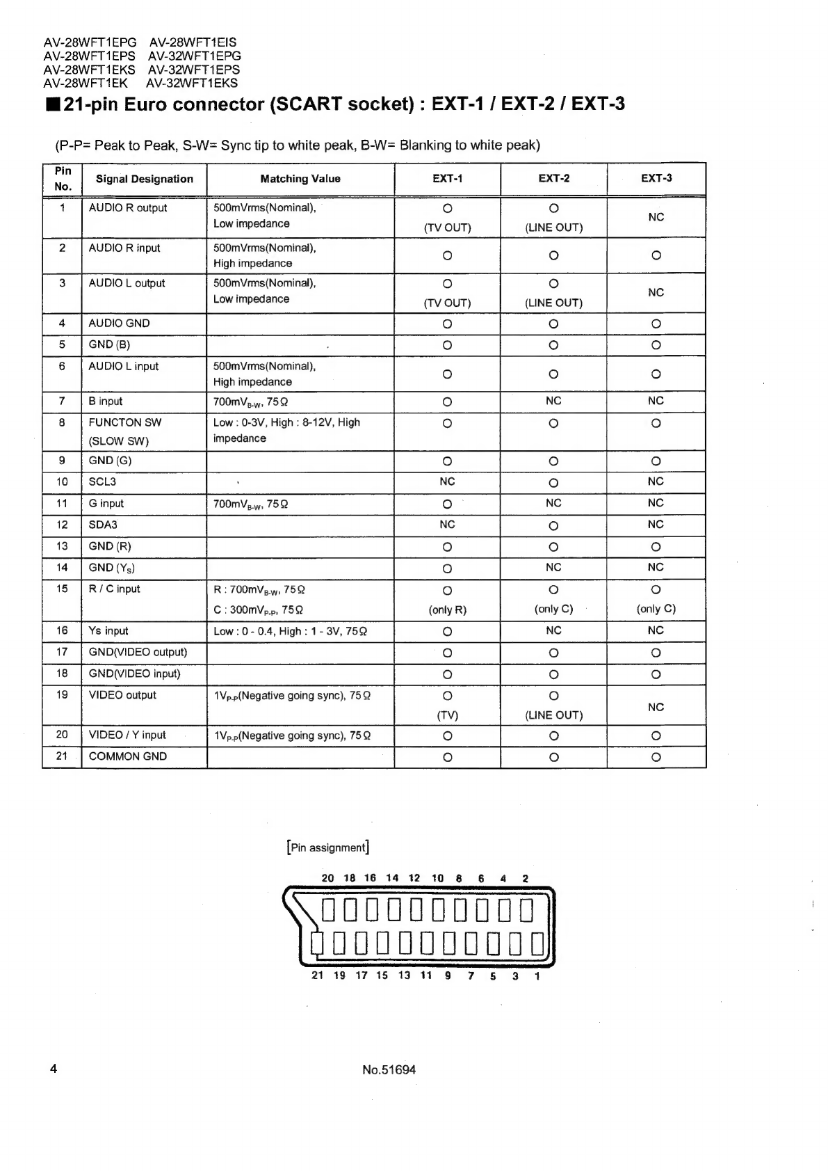
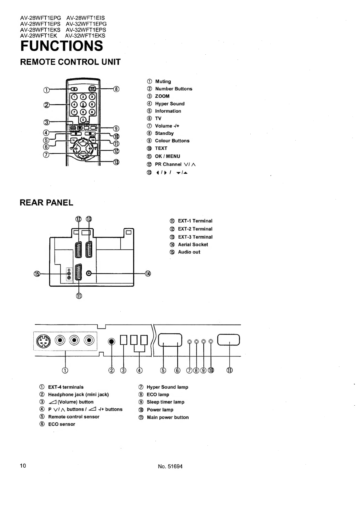
JVC AV-28WFT1EPG User manual
Other JVC TV manuals

JVC
JVC AV-29FH1BUGC Quick start guide

JVC
JVC AV-28BH8EEB User manual

JVC
JVC AV-16N8 User manual

JVC
JVC AV-21B17 User manual

JVC
JVC AV-28PS4N Quick start guide

JVC
JVC AV-28BK5ECB User manual

JVC
JVC PD-Z50DX4/S User manual

JVC
JVC AV-14FT Use and maintenance manual

JVC
JVC AV-28BH8EPB User manual

JVC
JVC InteriArt AV-28R47SK User manual