JVC AV-T2122 User manual

No.51866
Aug.2001
A
V-T2122
1COPYRIGHT © 2001 VICTOR COMPANY OF JAPAN, LTD. Sept. 2001
AV-T2122/AR
CONTENTS
!SPECIFICATIONS ・・・・・・・・・・・・・・・・・・・・・・・・・・・・・・・・
・・・・・・・・・・・・・・・・・・・・・・・・・・・・・・・・・・・・・・・・・・・・・・・・・・・・・・・・・・・・・・・・
・・・・・・・・・・・・・・・・・・・・・・・・・・・・・・・・ ・・・・・・・・・・・・・・・・・・・・・・・・・・・・・
・・・・・・・・・・・・・・・・・・・・・・・・・・・・・・・・・・・・・・・・・・・・・・・・・・・・・・・・・・
・・・・・・・・・・・・・・・・・・・・・・・・・・・・・ 2
!SAFETY PRECAUTIONS ・・・・・・・・・・・・・・・・・・・・・・・・・・・・・・・・
・・・・・・・・・・・・・・・・・・・・・・・・・・・・・・・・・・・・・・・・・・・・・・・・・・・・・・・・・・・・・・・・
・・・・・・・・・・・・・・・・・・・・・・・・・・・・・・・・ ・・・・・・・・・・・・・・・・・・・・・・・
・・・・・・・・・・・・・・・・・・・・・・・・・・・・・・・・・・・・・・・・・・・・・・
・・・・・・・・・・・・・・・・・・・・・・・ 3
!FEATURES・・・・・・・・・・・・・・・・・・・・・・・・・・・・・・・・
・・・・・・・・・・・・・・・・・・・・・・・・・・・・・・・・・・・・・・・・・・・・・・・・・・・・・・・・・・・・・・・・
・・・・・・・・・・・・・・・・・・・・・・・・・・・・・・・・ ・・・・・・・・・・・・・・・・・・・・・・・・・・・・・・・・
・・・・・・・・・・・・・・・・・・・・・・・・・・・・・・・・・・・・・・・・・・・・・・・・・・・・・・・・・・・・・・・・
・・・・・・・・・・・・・・・・・・・・・・・・・・・・・・・・ ・・・
・・・・・・
・・・ 4
!FUNCTIONS・・・・・・・・・・・・・・・・・・・・・・・・・・・・・・・・
・・・・・・・・・・・・・・・・・・・・・・・・・・・・・・・・・・・・・・・・・・・・・・・・・・・・・・・・・・・・・・・・
・・・・・・・・・・・・・・・・・・・・・・・・・・・・・・・・ ・・・・・・・・・・・・・・・・・・・・・・・・・・・・・・・・
・・・・・・・・・・・・・・・・・・・・・・・・・・・・・・・・・・・・・・・・・・・・・・・・・・・・・・・・・・・・・・・・
・・・・・・・・・・・・・・・・・・・・・・・・・・・・・・・・ ・・
・・・・
・・ 4
!SPECIFIC SERVICE INSTRUCTIONS ・・・・・・・・・・・・・・・・・・・・・・・・・・・・・・・・
・・・・・・・・・・・・・・・・・・・・・・・・・・・・・・・・・・・・・・・・・・・・・・・・・・・・・・・・・・・・・・・・
・・・・・・・・・・・・・・・・・・・・・・・・・・・・・・・・ ・・・・・・・・・・・・・
・・・・・・・・・・・・・・・・・・・・・・・・・・
・・・・・・・・・・・・・ 6
!SERVICE ADJUSTMENTS ・・・・・・・・・・・・・・・・・・・・・・・・・・・・・・・・
・・・・・・・・・・・・・・・・・・・・・・・・・・・・・・・・・・・・・・・・・・・・・・・・・・・・・・・・・・・・・・・・
・・・・・・・・・・・・・・・・・・・・・・・・・・・・・・・・ ・・・・・・・・・・・・・・・・・・・・・
・・・・・・・・・・・・・・・・・・・・・・・・・・・・・・・・・・・・・・・・・・
・・・・・・・・・・・・・・・・・・・・・ 10
!PARTS LIST・・・・・・・・・・・・・・・・・・・・・・・・・・・・・・・・
・・・・・・・・・・・・・・・・・・・・・・・・・・・・・・・・・・・・・・・・・・・・・・・・・・・・・・・・・・・・・・・・
・・・・・・・・・・・・・・・・・・・・・・・・・・・・・・・・ ・・・・・・・・・・・・・・・・・・・・・・・・・・・・・・・・
・・・・・・・・・・・・・・・・・・・・・・・・・・・・・・・・・・・・・・・・・・・・・・・・・・・・・・・・・・・・・・・・
・・・・・・・・・・・・・・・・・・・・・・・・・・・・・・・・ ・
・・
・29
★
OPERATING INSTRUCTIONS
★
STANDARD CIRCUIT DIAGRAM (APPENDIX) ・・・・・・・・・・・・・・・・・・・・・・・・・・・・・・・・
・・・・・・・・・・・・・・・・・・・・・・・・・・・・・・・・・・・・・・・・・・・・・・・・・・・・・・・・・・・・・・・・
・・・・・・・・・・・・・・・・・・・・・・・・・・・・・・・・ ・・・・・
・・・・・・・・・・
・・・・・ 2-1
SERVICE MANUAL
COLOR TELEVISION
BASIC CHASSIS
GA2
!!

No.51866
A
V-T2122
8
MEMORY IC REPLACEMENT
1. Memory IC
This model uses a memory IC.
The memory IC stores data for proper operation of video and deflection circuits.
When replacing, be sure to use an IC containing this (initial value) data.
2. Memory IC replacement procedure
PROCEDURE SCREEN DISPLAY
(1) Power off
Switch off the power and disconnect the power cord from the wall
outlet.
(2) Replace the memory IC.
Be sure to use memory ICs written with the initial data values.
(3) Power on
Connect the power cord to the wall outlet and switch on the power.
(4) System constant check and setting
1) Simultaneously press the DISPLAY key and VIDEO STATUS key
of the remote control unit.
2) The SERVICE MENU screen of Fig.1 is displayed.
3) While the SERVICE MENU is displayed, again simultaneously
press the DISPLAY and VIDEO STATUS keys to display the Fig.2
SYSTEM CONSTANT screen.
4) Refer to the SYSTEM CONSTANT table and check the setting
items. Where these differ, select the setting item with the MENU
UP / DOWN key and adjust the setting with the MENU LEFT /
RIGHT keys. (The letters of the selected item are displayed in
yellow.)
5) After adjusting, release the MENU LEFT / RIGHT key to store the
setting value.
6) Press the EXIT key twice to return the normal screen.
(5) Receive channel setting
Refer to the OPERATING INSTRUCTIONS (USER’S GUIDE) and
set the receive channels (Channels Preset) as described.
(6) User settings
Check the user setting items according to Table 2-1 and 2-2.
Where these do not agree, refer to the OPERATING
INSTRUCTIONS (USER’S GUIDE) and set the items as described.
(7) SERVICE MENU setting
Verify what to set in the SERVICE MENU, and set whatever is
necessary. (Fig.1) Refer to the SERVICE ADJUSTMENT for setting.
SYSTEM CONSTANT
SELECT BY
OPERATE BY EXIT BY
VIDEO : 2
AUDIO : MTS
VARI. OUT : NO
GAME : YES
CINEMA : YES
EXIT
SYSTEM CONSTANT
SELECT BY
OPERATE BY EXIT BY
CCD : YES
RETURN+ : YES
SURROUND : YES
M37272MA-
×××
××××××
×××
SP
EXIT
SERVICE MENU
SELECT BY
OPERATE BY EXIT BY
IT
PICTURE SOUND
VIDEO STATUS OTHERS
LOW LIGHT HIGH LIGHT
RF AFC CHK
VCO (CW) I2C BUS CTRL
EXIT
Fig.1
Fig.2

No.51866
A
V-T2122
9
SETTING OF SYSTEM CONSTANT SET
Setting item Setting content Setting value
VIDEO 2
AUDIO MTS
VARI. OUT NO
GAME YES
CINEMA YES
CCD YES
RETURN + YES
SURROUND YES
USER SETTING VALUES
1.Setting of FUNCTION
Setting item Setting value Setting item Setting value
MAIN POWER OFF DISPLAY OFF
SUB POWER ON SLEEP TIMER 0 MIN
CHANNEL CH 02 VIDEO STATUS ESTANDAR
CAPTION OFF(CC1/T1) PICTURE BOOSTER OFF
VOLUME 10 COLOR SYSTEM AUTO
TV/VIDEO TV HYPER SURROUND OFF
2.Setting of MENU
Setting item Setting value Setting item Setting value
TINTE ESTANDAR ALTAVOCES SI
COLOR ESTANDAR CHILD LOCK NO
CONTRASTE ESTANDAR TEMPORIZADOR NO
BRILLO ESTANDAR LISTA DE CANAIS SET OPTIONALLY
DETALLE ESTANDAR AJUSTE CODIGO DE ACCESO Unnecessary to Set
GRAVES CENTER PANTALLA AZUL NO
AGUDOS CENTER FONDO NEGRO SI (SIM)
BALANCE CENTER IDIOMA ESP.
MTS ESTÉREO SUBTITULOS OCULTOS NO(CC1/T1)
12
MONO PH.MONO MTS
YES NO
YES NO
YES NO
YES NO
YES NO
YES NO
Table 1
Table 2-2
Table 2-1

No.51866
A
V-T2122
10
SERVICE ADJUSTMENTS
ADJUSTMENT PREPARATION$
$$
$
1. You can make the necessary adjustments for this unit with either the remote control unit or with the adjustment equipment and
parts as given below.
2. Adjustment with the remote control unit is made on the basis of the initial setting values, however, the new setting values which
set the screen to its optimum condition may differ from the initial settings.
3. Make sure that AC power is turned on correctly..
4. Turn on the power for the set and test equipment before use, and start the adjustment procedures after waiting at least 30 minutes
5. Unless otherwise specified, prepare the most suitable reception or input signal for adjustment.
6. Never touch any adjustment parts, which are not specified in the list for this adjustment-variable resistors, transformers, condensers, etc.
7. Presetting before adjustment.
Unless otherwise specified in the adjustment instructions, preset the following functions with the remote control unit.
VIDEO STATUS ESTANDAR
GRAVES, AGUDOS, BALANCE CENTER
ADJUSTMENT EQUIPMENT
1. DC voltmeter(or digital voltmeter)
2. Oscilloscope
3. Signalgenerator ( Pattern generator ) [NTSC%M]![PAL-M] [PAL-N]
4. Remote control unit
5. TV audio multiplex signal generator
6. Frequency counter
ADJUSTMENT ITEMS
●B1 POWER SUPPLY
●IF VCO adjustment
●RF AGC adjustment
●FOCUS adjustment
●
DEFLECTION adjustment
V. HEIGHT, V. POSITION, V. LIN., V S CR adjustment
H. POSITION adjustment
●VIDEO / CHROMA adjustment
WHITE BALANCE (Low light) adjustment
WHITE BALANCE (High light) adjustment
SUB BRIGHT adjustment
SUB CONTRAST adjustment
SUB COLOR adjustment
SUB TINT adjustment
●MTS adjustment
INPUT LEVEL adjustment
STEREO VCO adjustment
SAP VCO adjustment
FILTER check
SEPARATION adjustment

No.51866
A
V-T2122
11
ADJUSTMENT LOCATIONS
MAIN PWB
FRONT
HV
UPPER : FOCUS
LOWER : SCREEN
U
T
TUNER
IC101
IC704
IC701
MENU
CH-CH+VOL-
VOL+
F901
T522
T111
31
GND(TP-E)
PW
DEG.
S
SW
B1
B1(TP-91)
CW
MPX
AV IN OUT
5 1
31
X
CRT SOCKET PWB
(Within MAIN PWB ASS'Y)
TP-E
(
SOLDER SIDE
)
TOP
CRT EARTH
(BRAIDED ASS'Y)
E1
TP-47B

No.51866
A
V-T2122
12
BASIC OPERATION OF SERVICE MENU
1. Operate the SERVICE MENU with the REMOTE CONTROL UNIT.
2. In general!
!!!basic setting!
!!!(adjustments) items or verifications are performed in the SERVICE MENU.
(1) PICTURE・・・・・・・・・・・・・・・・・・・ This set the setting values (adjustment values) of the VIDEO/CHROMA and DEFLECTION circuits.
(2) SOUND ・・・・・・・・・・・・・・・・・・・・ This set the setting values (adjustment values) of the AUDIO circuit.
(3) VIDEO STATUS ・・・・・・・・・・・・・ This is used when the THEATER and GAME MODE is adjusted.
(4) OTHERS ・・・・・・・・・・・・・・・・・・・ This is used when the OTHERS MODE is adjusted.
(5) LOW LIGHT・・・・・・・・・・・・・・・・・ This sets the setting values (adjustment values) of the WHITE BALANCE circuit.
(6) HIGH LIGHT ・・・・・・・・・・・・・・・・ This sets the setting values (adjustment values) of the WHITE BALANCE circuit.
(7) RF AFC CHK・・・・・・・・・・・・・・・・ This is used when the RF AFC CHK MODE is verified. [Do not adjust]
(8) VCO (CW) ・・・・・・・・・・・・・・・・・・ This is used when the IF VCO is adjusted.
(9) I2C BUS CTRL・・・・・・・・・・・・・・・ This is used when ON/OFF of the I2C BUS CTRL is set. [Fixed ON]
3. Basic Operations of the SERVICE MENU
(1) How to enter the SERVICE MENU.
Press the DISPLAY key and VIDEO STATUS key!of the remote control unit at the same time to enter the SERVICE MENU screen ①
shown in figure page later.
(2) SERVICE MENU screen selection
Press the UP / DOWN key of the MENU to select any of the following items.
(The letters of the selected items are displayed in yellow.)
●PICTURE ●SOUND
●VIDEO STATUS ●OTHERS
●LOW LIGHT ●HIGH LIGHT
●RF AFC CHK
●VCO (CW) ●I
2C BUS CTRL
(3) Enter the any setting ( adjustment ) mode
"PICTURE, SOUND and OTHERS mode
1) If select any of PICTURE, SOUND or OTHERS items, and the LEFT / RIGHT key is pressed from SERVICE MENU ( MAIN
MENU ), the screen ②will be displayed as shown in figure page later.
2) Then the UP / DOWN key is pressed, the PICTURE mode screen ③or the SOUND mode screen ④or the OTHERS mode
screen ⑤is displayed, and the PICTURE, SOUND or OTHERS setting can be performed.
"VIDEO STATUS, LOW LIGHT, HIGH LIGHT, RF AFC!
!!!CHK,!
!!!VCO (CW) and I2C BUS CTRL mode
1) If select any of VIDEO STATUS / LOW LIGHT / HIGH LIGHT / RF AFC CHK / VCO (CW) / I2C BUS CTRL items, and the LEFT
/ RIGHT key is pressed from SERVICE MENU ( MAIN MENU ), the screens ⑥⑦⑧⑨⑩⑪will be displayed as shown in
figure page later.
2) Then the settings or verifications can be performed.

No.51866
A
V-T2122
13
HIGH LIGHT
***
******
*** ***
******
***
TOO HIGH
ABOVE REFERENCE
BELOW REFERENCE
TOO LOW
SYNC : YES
①
①①
①
SERVICE MENU
(
MAIN MENU
)
②
②②
②
SCREEN
⑧
⑧⑧
⑧
HIGH LIGHT MODE
⑩
⑩⑩
⑩
VOC
(
CW
)
MODE
⑪
⑪⑪
⑪
I
2
C BUS CTRL MODE
⑥
⑥⑥
⑥
VIDEO STATUS MODE
⑨
⑨⑨
⑨
RF AFC CHK MODE
⑦
⑦⑦
⑦
LOWLIGHT MODE
④
④④
④
SOUND MODE
⑤
⑤⑤
⑤
OTHERS MODE
③
③③
③
PICTURE MODE
SERVICE MENU
SELECT BY
OPERATE BY EXIT BY
PICTURE SOUND
VIDEO STATUS OTHERS
LOW LIGHT HIGH LIGHT
RF AFC CHK
VCO
(
CW
)
I2C BUS CTRL
EXIT
EXIT BY
EXIT
RF AFC ON
FINE
**
****
**
SELECT BY
OPERATE BY EXIT BY
EXIT
EXIT BY
EXIT
I2C BUS ON
OPERATE BY EXIT BY
EXIT
SELECT BY EXIT BY
EXIT
SELECT BY
OPERATE BY EXIT BY
1. NOISE
***
******
***
STATUS
****
********
****
EXIT
CINEMA
SELECT BY
OPERATE BY EXIT BY
TINT G DRIVE
COLOR B DRIVE
PICTURE R CUT.
BRIGHT G CUT.
DETAIL B CUT.
EXIT
***
******
*** ***
******
***
***
******
*** ***
******
***
***
******
*** ***
******
***
***
******
*** ***
******
***
***
******
*** ***
******
***
GAME
SELECT BY
OPERATE BY EXIT BY
TINT G DRIVE
COLOR B DRIVE
PICTURE R CUT.
BRIGHT G CUT.
DETAIL B CUT.
EXIT
***
******
*** ***
******
***
***
******
*** ***
******
***
***
******
*** ***
******
***
***
******
*** ***
******
***
***
******
*** ***
******
***
BRIGHT
***
******
***
***
******
*** *** ***
*** ****** ***
*** ***
BRIGHT EXIT BY
EXIT
SELECT BY
OPERATE BY EXIT BY
1. PICTURE
***
******
***
*****
**********
***** ****
********
****
EXIT
SELECT BY
OPERATE BY EXIT BY
1. OSD HP
***
******
***
EXIT
[DO NOT ADJUST]
[FIXED ON]
Press
VIDEO
STATUS
Ke
y

No.51866
A
V-T2122
14
(4) Setting method
1) UP / DOWN key of the MENU
Select the SETTING ITEM.
2) LEFT / RIGHT key of the MENU
Setting (adjust) the SETTING VALUE of the SETTING ITEM.
When the key is released the SETTING VALUE will be stored
(memorized).
3) EXIT key
Returns to the previous screen.
[NOTE] (PICTURE MODE ONLY)
When the INITIAL SETTING VALUE is turned to yellow, you can adjust the
values but you cannot adjust the values when it is turned to red.
(Because the signal conditions, etc. are not met.)
(5) Releasing SERVICE MENU
1) After returning to the SERVICE MENU upon completion of the setting
(adjustment) work, press the EXIT key again.
★The settings for LOW LIGHT and HIGH LIGHT are described in the WHITE
BALANCE page of ADJUSTMENT.
★The setting for VCO (CW) are described in the IF VCO page of ADJUSTMENT.
SELECT BY
OPERATE BY EXIT BY
IT
1. NOISE
***
******
***
STATUS
****
********
****
EXIT
SOUND MODE
SELECT BY
OPERATE BY EXIT BY
IT
EXIT
1. PICTURE
***
******
***
*****
**********
***** ****
********
****
PICTURE MODE
INITIAL
SETTING VALUE
↓(Adjust)
SETTING VALUE
SETTING
ITEM
SELECT BY
OPERATE BY EXIT BY
IT
1. OSD HP
***
******
***
EXIT
OTHERS MODE
VIDEO STATUS MODE
CINEMA
SELECT BY
OPERATE BY EXIT BY
I
T
TINT G DRIVE
COLOR B DRIVE
PICTURE R CUT.
BRIGHT G CUT.
DETAIL B CUT.
EXIT
***
******
*** ***
******
***
***
******
*** ***
******
***
***
******
*** ***
******
***
***
******
*** ***
******
***
***
******
*** ***
******
***
GAME
SELECT BY
OPERATE BY EXIT BY
I
T
TINT G DRIVE
COLOR B DRIVE
PICTURE R CUT.
BRIGHT G CUT.
DETAIL B CUT.
EXIT
***
******
*** ***
******
***
***
******
*** ***
******
***
***
******
*** ***
******
***
***
******
*** ***
******
***
***
******
*** ***
******
***
Press
VIDEO
STATUS
Key
The letter of the selected
Items are displayed in yellow.

No.51866
A
V-T2122
15
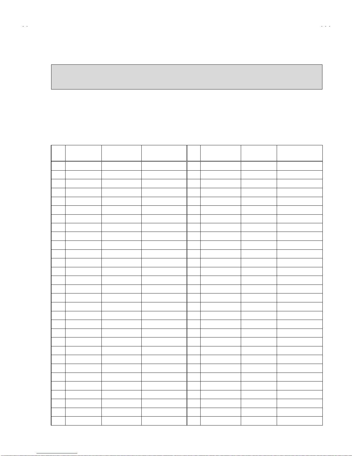
INITIAL SETTING VALUE OF SERVICE MENU
1. Adjustment of the SERVICE MENU is made on the basis of the initial setting values; however, the new setting values
which set the screen in its optimum condition may differ from the initial setting.
2. Do not change the initial Setting Values of the Setting (Adjustment) items not listed In “ADJUSTMENT”.
"
""
"PICTURE MODE
#The four setting items in the video mode No.8 EXT PIC., No.9 EXT BRI., No.10 EXT COL. and No.11 EXT TINT are linked to the items in
the TV MODE No.1 PICTURE, No.2 BRIGHT, No.5 COL. NTSC and No.6 TINT, respectively. When the setting items in the TV mode are
adjusted, the values in the setting items in the video mode are revised automatically to the same values in the TV mode.(The initial setting
values given in ( ) are off-set values.)
#When the four items (No.8, 9, 10 and 11) are adjusted in the video mode, the setting values in each item are revised independently.
No. Setting item Variable range Initial setting value No. Setting item Variable range Initial setting value
1. PICTURE 0~127 65 31. C-TRAP 0 / 1 0
2. BRIGHT 0~127 64 32. C-TR. FO 0~32
3. COL. PALM 0~127 70 33. C-TRAP Q 0~30
4. COL. PALN 0~127 70 34. FIX B/W 0 / 1 0
5. COL. NTSC 0~127 80 35. APA P. FO 0~31
6. TINT 0~127 65 36. DC TRAN. 0~77
7. TV DTL 0~63 38 37. B. ST. SW 0~70
8. EXT PIC. ±25 (0) 38. B. ST. PO. 0 / 1 0
9. EXT BRI. ±25 (+5) 39. ABL GAIN 0~74
10. EXT COL. ±25 (0) 40. ABL PO 0~70
11. EXT TINT ±25 +1 41. HALF T. 0~21
12. EXT DTL 0~63 35 42. DRV G SW 0 / 1 0
13. P/N KILL 0 / 1 143. NT. COMB 0 / 1 1
14. Y S CONT 0~31 31 44. COIN DET 0~33
15. TV Y-DL 0~7145. NOISE L 0~33
16. EXT Y-DL 0~7246. VCD MODE 0 / 1 0
17. WPL SW 0 / 1 047. V AGC SP 0 / 1 0
18. Y GAMMA 0 / 1 048. H POS. 50 0~31 7
19. P/N G P 0 / 1 049. H BLK. 50 0~70
20. COL. L SW 0 / 1 150. V POS. 50 0~70
21. COL. LMT. 0~3151. V SIZE50 0~127 87
22. PN C. ATT 0~3152. V S CR50 0~127 28
23. OFST. SW 0 / 1 053. V LIN. 50 0~31 4
24. OFSET. B-Y 0~15 854. H POS. 60 0~31 12
25. OFSET. R-Y 0~15 855. H BLK. 60 0~70
26. C-TOF SW 0 / 1 156. V POS. 60 0~70
27. TV T FO 0~3157. V SIZE60 0~127 88
28. TV T Q 0~3058. V S CR60 0~127 48
29. EXT T FO 0~3059. V LIN. 60 0~31 4
30. EXT T Q 0~3060. RF AGC 0~255 160

No.51866
A
V-T2122
16
"SOUND MODE
No. Setting item Variable range Initial setting value
1. NOISE 0 / 1 1
2. IN LEVEL 0~63 20
3. FH MON. 0 / 1 0
4. ST VCO 0~63 25
5. PILOT 0 / 1 0
6. FILTER 0~63 30
7. LOW SEP. 0~63 22
8. HI SEP. 0~63 23
9. 5FH MON. 0 / 1 0
10. SAP VCO 0~63 26
11. IN GAIN 0 / 1 0
12. FIL. OFF ±10 0
"VIDEO STATUS MODE
Initial setting value
No.Setting (Adjustment) item Variable range CINEMA GAME
1. TINT ±20 00
2. COLOR ±20 -3 -3
3. PICTURE ±20 -10 -10
4. BRIGHT ±20 00
5. DETAIL ±15 0-5
6. G DRIVE -99~+50 -22 0
7. B DRIVE -99~+50 -54 0
8. R CUT. ±10 00
9. G CUT. ±10 00
10. B CUT ±10 00

No.51866
A
V-T2122
17
"OTHERS MODE!
!!!
No. Setting (Adjustment) item Variable range Initial setting value
1. OSD HP 0~31 23
2. OSD VP 0~15 12
3. H CK SW 0 / 1 0
"LOW LIGHT MODE!
!!!
Setting (Adjustment) item Variable range Initial setting value
R CUTOFF 0~255 20
G CUTOFF 0~255 20
B CUTOFF 0~255 20
"HIGH LIGHT MODE!
!!!
Setting (Adjustment) item Variable range Initial setting value
G DRIVE 0~255 128
B DRIVE 0~255 128
"RF AFC CHECK MODE!
!!!
Setting (Adjustment) item Variable range Initial setting value
RF AFC ON / OFF ON
FINE -77~+77 ±**
"I2C BUS CTRL MODE!
!!!
Setting (Adjustment) item Variable range Initial setting value
I2C BUS ON / OFF [Fixed ON]
(DO NOT ADJUST)

No.51866
A
V-T2122
18
■
■■
■ADJUSTMENTS
!
!!!B1 POWER SUPPLY
Item Measuring
instrument Test point Adjustment item Description
Check of
B1 POWER
SUPPLY
DC Voltmeter B1 ( B1
Connector
1pin)
(TP-91)
TP-E(#)
( B1
Connector
3pin)
1. Receive a black and white signal (color off). (NTSC)
2. Connect the DC voltmeter to B1 connector 1 pin (TP-91)
and TP-E(#) (B1 connector 3 pin).
3. Confirm that the voltage is DC134.5V±2V.
IF VCO ADJUSTMENT
Item Measuring
instrument Test point Adjustment item Description
IF VCO
adjustment Signal
generator CW TRANSF. (T111)
[VCO (CW)] mode
"Under normal conditions, no adjustment is required.
1. Receive a broadcast. (use channels without offset frequency).
2. Select the VCO(CW) mode from the SERVICE MENU.
3. Confirm the color change (yellow) from “TOO HIGH”to
“TOO LOW”by CW TRANSF. and “SYNC : YES”being
shown on the screen. Then, adjust CW TRANSF. until
“BELOW REFERENCE”mark turns yellow and confirm
again “SYNC : YES”being shown on the screen.
RF AGC ADJUSTMENT
RF AGC
adjustment No.60 RF AGC 1. Receive a broadcast.
2. Select “No.60 RF AGC” of the PICTURE mode in SERVICE
MENU.
3. Press the MUTE key and turn off color.
4. With the MENU LEFT key, get noise in the screen picture. (0
side of setting value)
5. Press the MENU RIGHT key and stop when noise disappears
from the screen.
6. Change to other channels and make sure that there is no
irregularity.
7. Press the MUTE key and get color out.
FOCUS ADJUSTMENT
FOCUS
adjustment Signal
generator FOCUS VR
[In HVT] 1. Receive a crosshatch signal.
2. While looking at the screen, adjust FOCUS VR so that the
vertical and horizontal lines will be clear and in fine detail.
3. Make sure that the picture is in focus even when the screen
gets darkened.
EXIT BY
IT
TOO HIGH
ABOVE REFERENCE
BELOW REFERENCE
TOO LOW
SYNC : YES
EXIT
YELLOW

No.51866
A
V-T2122
19
DEFLECTION ADJUSTMENT
The setting (adjustment) using the REMOTE CONTROL UNIT is made on the basis of the initial setting values.
The setting values which adjust the screen to the optimum condition can be different from the initial setting values.
Item Measuring
instrument Test point Adjustment item Description
No.56 V POS. 60
No.57 V SIZE 60
No.58 V S CR60
No.59 V. LIN. 60
[60Hz]
1. Receive a crosshatch signal.(NTSC or PAL-M)
2. Confirm that the value of PICTURE MODE “No.56 V POS.
60”is 0.
3. Confirm the initial setting value of the “No.57 V SIZE 60”,
No.58 V S CR60”and “No.59 V LIN. 60”.
4. Adjust the vertical screen size to 92% with the PICTURE
MODE “No.57 V SIZE60”.
5. Adjust the PICTURE MODE “No.59 L LIN. 60”and “No.58
V S CR60”to get the best vertical linearity.
NOTE :
The PICTURE MODE “No.56 V POS. 60” is fixed on value 0.
V. HEIGHT,
V. POSITION,
V. LIN.
V. S CR
adjustment
Signal
generator
No.50 V POS.50
No.51 V SISE 50
No.52 V S CR50
No.53 V LIN.50
[50Hz]
1. Receive a crosshatch signal. (PAL-N)
2. Confirm the initial setting value of the “No.50 V POS.50”,
“No.51 V SIZE 50” , “No.52 V S CR 50” and “No.53 V LIN.50”.
3. Adjust the vertical screen size to 92% with the PICTURE
MODE “No.51 V SIZE50”.
4. Adjust the PICTURE MODE “No.53 V LIN.50” and “No.52 V S
CR50” to get the best vertical linearity.
5. Adjust the PICTURE MODE “No.50 V POS.50” so that the
vertical center line comes close to the CRT vertical center as
much as possible.
"Readjust V SIZE, V LIN., V S CR if necessary.
No.54 H POS.60
[60Hz]
1. Receive a crosshatch signal. (NTSC or PAL-M)
2. Select the “No.54 H POS. 60” of the PICTURE mode in
SERVICE MENU.
3. Confirm the initial setting value of the "No.54 H POS. 60".
4. Adjust the “No.54 H POS. 60” until the screen will be
horizontally centered.
H. POSITION
adjustment Signal
generator
No.48 H POS.50
[50Hz]
1. Receive a crosshatch signal. (PAL-N)
2. Select the “No.48 H POS. 50” of the PICTURE mode in
SERVICE MENU.
3. Confirm the initial setting value of the "No.48 H POS. 50".
4. Adjust the “No.48 H POS. 50” until the screen will be
horizontally centered.
Pictu
r
size
100
%
Picture size
(
100%
)
Screen
size
(
92%
)
Scree size

No.51866
A
V-T2122
20
VIDEO / CHROMA !
!!!ADJUSTMENT
The setting (adjustment) using the REMOTE CONTROL UNIT is made on the basis of the initial setting values.
The setting values which adjust the screen to the optimum condition can be different from the initial setting values.
Do not change the initial setting values of the setting items not listed in “ADJUSTMENT”.
Item Measuring
instrument Test point Adjustment item Description
WHITE
BALANCE
(Low Light)
adjustment
Signal
generator
Remote
control unit
BRIGHT
R CUTOFF
G CUTOFF
B CUTOFF
SCREEN VR
1. Receive a black and white signal (color off).
2. Select the LOW LIGHT mode from the SERVICE MENU.
3. Confirm the Initial setting value of “BRIGHT”, “R CUTOFF”, “G
CUTOFF” and “B CUTOFF”.
4. Display a single horizontal line by pressing the ①
①①
①key of the
remote control unit.
5. Turn thescreen VR all the way to the left.
6. Turn the screen VR gradually to the right from the left until
either one of the red, blue or green colors appears faintly.
7. Adjust the two colors which did not appear until the single
horizontal line that is displayed becomes white using the ④
④④
④to
⑨
⑨⑨
⑨keys of the remotecontrol unit.
8. Turn the screen VR until the single horizontal line is displayed
faintly.
9. Press the
②
②②
②key to return to the regular screen.
WHITE
BALANCE
(High Light)
adjustment
Signal
generator
Remote
control unit
G DRIVE
B DRIVE 1. Receive a black and white signal (color off).
2. Select the HIGH LIGHT mode in the SERVICE MENU.
3. Confirm the initial setting value of “G DRIVE” and “B DRIVE”.
4. Adjust the screen color to white with the⑤
⑤⑤
⑤, ⑥
⑥⑥
⑥, ⑧
⑧⑧
⑧and ⑨
⑨⑨
⑨
keys of the remotecontrol unit.
[HIGHLIGHT]MODE
EXIT BY
IT
HIGH LIGHT
EXIT
***
******
******
******
***
B DRIVE
G DRIVE
Remote Control Unit
①key : H.LINE ON
②key : H.LINE OFF
③key : EXIT
⑤key : G DRIVE ▲
⑥key : B DRIVE ▲
⑧key : G DRIVE ▼
⑨key : B DRIVE ▼
REMOTE CONTROL UNIT
9
99
9
B CUTOFFG CUTOFF
8
88
8
R CUTOFF G CUTOFF
H.LINE OFF EXITH.LINE ON
1
11
1
B CUTOFF
R CUTOFF
7
77
7
4
44
45
55
5 6
66
6
2
22
2 3
33
3
[LOWLIGHT]MODE
BRIGHT EXIT BY
IT
BRIGHT
EXIT
***
******
***
*** *** ***
*** *** ****** *** ***
*** *** ***
BRIGHT
G CUTOFF
B CUTOFF
R CUTOFF

No.51866
A
V-T2122
21
Item Measuring
instrument Test point Adjustment item Description
SUB BRIGHT
adjustment Remote
control unit No.2 BRIGHT 1. Receive a broadcast.
2. Select “No.2 BRIGHT” of the PICTURE mode in SERVICE
MENU.
3. Confirm the initial setting value of the “No.2 BRIGHT” .
4. If the brightness is not the best with the initial setting value,
make fine adjustment of the “No.2 BRIGHT” until you get the
optimum brightness.
SUB
CONTRAST
adjustment
Remote
control unit No.1 PICTURE 1. Receive a broadcast.
2. Select “No.1 PICTURE” of the PICTURE mode in SERVICE
MENU.
3. Confirm the initial setting value of the “No.1 PICTURE”.
4. If the contrast is not the best with the initial setting value, make
fine adjustment of the “No.1 PICTURE” until you get the
optimum contrast.
SUB COLOR
adjustment Remote
control unit No.3 COL. PALM
No.4 COL. PALN
No.5 COL. NTSC
[PAL-M]
1. Receive a PAL-M color bar signal.
2. Select “No.3 COL. PALM” of the PICTURE mode in SERVICE
MENU.
3. Confirm the initial setting value of the “No.3 COL. PALM”.
4. If the color is not the best with the initial setting value, make
fine adjustment until you get the best color.
[PAL-N]
1. Receive a PAL-N color bar signal.
2. Select “No.4 COL. PALN” of the PICTURE mode in SERVICE
MENU.
3. Confirm the initial setting value of the “No.4 COL. PALN”.
4. If the color is not the best with the initial setting value, make
fine adjustment until you get the best color.
[NTSC]
1. Receive a NTSC color bar signal.
2. Select “No.5 COL. NTSC” of the PICTURE mode in SERVICE
MENU.
3. Confirm the initial setting value of the “No.5 COL. NTSC”.
4. If the color is not the best with the initial setting value, make
fine adjustment until you get the best color.
SUB TINT
adjustment Remote
control unit No. 6 TINT 1. Receive a NTSC color bar signal.
2. Select “No. 6 TINT” of the PICTURE mode in SERVICE
MENU.
3. Confirm the initial setting value of the “No. 6 TINT”.
4. If the tint is not the best with the initial setting value, make fine
adjustment until you get the best tint.

No.51866
A
V-T2122
22
MTS ADJUSTMENT
Item Measuring
instrument Test point Adjustment part Description
INPUT LEVEL
adjustment No.2 IN LEVEL 1. Select the “No.2 IN LEVEL” of the SOUND mode in SERVICE
MENU.
2. Verify that the
“No.2 IN LEVEL”is set at its initial setting
value.
STEREO VCO
adjustment Signal
generator
Frequency
counter
MPX
Connector
2 pin TVR
[MAIN PWB]
No.3 FH MON
No.4 ST VCO
1. Receive a NTSC RF signal (non modulated sound signal) from
the antenna terminal.
2. Select the “No.3 FH MON” of SOUND mode in SERVICE
MENU, change the setting value from 0 to 1.
3. Connect the frequency connector to pin 2 of MPX!
connector.
4. Select the “No.4 ST VCO”.
5. Confirm the initial setting value of the “No.4 ST VCO”.
6. Adjust the “No.4 ST VCO” so that the frequency counter will
display 15.73kHz±0.1kHz.
7. Select the “No.3 FH MON” of the SOUND mode, and reset the
setting value from 1 to 0.
SAP VCO
adjustment Signal
generator
Frequency
counter
MPX
Connector
4 pin SDA
3 pin GND
2 pin TVR
[MAIN PWB]
No.9 5FH MON.
No.10 SAP VCO.
1. Receive a NTSC RF signal (non modulated sound signal) from
the antenna terminal.
2. Connect between pin 4 of MPX connector and GND (pin
3 of MPX connector) through 1MΩresistor.
3. Select the “No.9 5FH MON.” of the SOUND mode in SERVICE
MENU, and reset the setting value from 0 to 1.
4. Connect the frequency connector to pin 2 (R.OUT) of
MPX connector.
5. Select the “No.10 SAP VCO”.
6. Confirm the initial setting value of “No.10 SAP VCO”.
7. Adjust the “No.10 SAP VCO” so that the frequency connector
will display 78.67kHz±0.5kHz.
8. Select the “No.9 5FH MON.” of the SOUND mode, and reset
the setting value from 1 to 0.
FILTER
check No.6 FILTER 1. Select the “No.6 FILTER” of the SOUND mode in SERVICE
MENU.
2. Verify that the “No.6 FILTER” is set at its initial setting value.

No.51866
A
V-T2122
23
Item Measuring
instrument Test point Adjustment part Description
SEPARATION
adjustment TV audio
multiplex
signal
generator
Oscilloscope
MPX
Connector
1 pin TVL
2 pin TVR
[MAIN PWB]
No.7 LOW SEP.
No.8 HI SEP.
1. Input a stereo L signal (300Hz) from the TV Audio multiplex
signal generator to the antenna terminal.!(NTSC)
2. Connect an oscilloscope to pin 2 (R.OUT) of MPX!
connector, and display one cycle portion of the 300Hz signal.
3. Select the “No.7 LOW SEP.” of the SOUND mode in SERVICE
MENU.
4. Confirm the initial setting value of the “No.7 LOW SEP.”.
5. Adjust the “No.7 LOW SEP.” so that the stroke element of the
300Hz signal will become minimum.
6. Change the connection of the oscilloscope to pin 1 (L.OUT)
of MPX connector, and enlarge the voltage axis.
7. Change the signal to 3kHz, and similarly adjust the “No.8 HI
SEP.”.
L-Channel
signal waveform R-Channel
crosstalk portion
Minimum
1 cycle

No.51866
A
V-T2122
24
PURITY, CONVERGENCE
PURITY ADJUSTMENT
1. Demagnetize CRT with the demagnetizer.
2. Loosen the retainer screw of the deflection yoke.
3. Remove the wedges.
4. Input a green raster signal from the signal generator, and turn
the screen to green raster.
5. Move the deflection yoke backward.
6. Bring the long lug of the purity magnets on the short lug and
position them horizontally. (Fig.2)
7. Adjust the gap between two lugs so that the GREEN RASTER
will come into the center of the screen. (Fig.3)
8. Move the deflection yoke forward, and fix the position of the
deflection yoke so that the whole screen will become green.
9. Insert the wedge to the top side of the deflection yoke so that it
will not move.
10. Input a crosshatch signal.
11. Verify that the screen is horizontal.
12. Input red and blue raster signals, and make sure that purity is
properly adjusted.
CRT
WEDGE DEFLECTION
YOKE
P / C
MAGNETS
P
46
PURITY MAGNETS
Long lug
Short lug
Bring the long lug over the short lug
and position them horizontally.
(
FRONT VIEW
)
GREEN RASTER
CENTER
P : PURITY MAGNET
4 : 4 POLES (convergence magnets)
6 : 6 POLES (convergence magnets)
$P/C MAGNETS
Fig.1
Fig.3
Fig.2

No.51866
A
V-T2122
25
STATIC CONVERGENCE ADJUSTMENT
1. Input a crosshatch signal.
2. Using 4-pole convergence magnets, overlap the red and blue
lines in the center of the screen (Fig.1) and turn them to
magenta (red/blue).
3. Using 6-pole convergence magnets, overlap the
magenta(red/blue) and green lines in the center of the screen
and turn them to white.
4. Repeat 2 and 3 above, and make best convergence.
DYNAMIC CONVERGENCE ADJUSTMENT
1. Move the deflection yoke up and down and overlap the lines in
the periphery. (Fig. 2)
2. Move the deflection yoke left to right and overlap the lines in the
periphery. (Fig. 3)
3. Repeat 1 and 2 above, and make best convergence.
●After adjustment, fix the wedge at the original position.
Fasten the retainer screw of the deflection yoke.
Fix the 6 magnets with glue.
(FRONT VIEW)
GREEN
(FRONT VIEW)
BLUE
RED
BLUE
GREEN
RED
RED
GREEN
BLUE
GREEN RED
BLUE
GREEN
(FRONT VIEW)
BLUE RED
BLUE GREEN
RED RED
GREEN
BLUE
GREEN
RED
BLUE
Fig.3
Fig.2
Fig.1

No.51866
A
V-T2122
26
HOW TO CHECK THE HIGH VOLTAGE HOLD DOWN CIRCUIT
1. HIGH VOLTAGE HOLD DOWN CIRCUIT
After repairing the high voltage hold down circuit shown in Fig. 1.
This circuit shall be checked to operate correctly.
2. CHECKING OF THE HIGH VOLTAGE HOLD DOWN CIRCUIT
(1) Turn the POWER SW ON.
(2) As shown in Fig.2, set the resistor (between X connector 1 & 3 ).
(3) Make sure that the screen picture disappears.
(4) Temporarily unplug the power cord.
(5) Remove the resistor (between X connector 1 & 3 ).
(6) Again plug the power cord, make sure that the normal picture is displayed on the screen.
B1
T522
Q942
HVT
HEATER
IC701
27 28
Q511
D510 4
Q941 Q522
10
4
3IC201
H-OUT T521
Q521
H-Vcc
R562
D561
FR561
X
C561
R563
D562
3 2 1
Fig. 1
RESISTOR
RESISTORRESISTOR
RESISTOR
C561
R563
3 2 1 X CONNECTOR
R562 FR561 D561
D562
Fig. 2
17.2kΩ
ΩΩ
Ω±
±±
±1% 1/4W
Fig. 2
Other manuals for AV-T2122
1
This manual suits for next models
1
Table of contents
Other JVC TV manuals

JVC
JVC I'Art AV-27CF36 User manual

JVC
JVC AV-28X4SK User manual

JVC
JVC InteriArt AV28WH5EU User manual

JVC
JVC AV-21KT1BPF User manual

JVC
JVC 0303-NIC-JMT User manual

JVC
JVC AV-N34301 User manual

JVC
JVC COLOUR TELEVISON AV-29LS24 User manual

JVC
JVC AV-21L11, AV-21L31, AV-25L31, User manual

JVC
JVC HD70G886 - 70" CRT TV Manual

JVC
JVC AV-14A14/A Administrator Guide