JVC I' Art AV-27F702 User manual

COLOR TELEVISION
USER'S GUIDE
For models:
AV-32F802
AV-32F702
AV-27F802
AV-27F702
Illustration of AV-27F802 and RM-C301G
IMPORTANT NOTETO THE CUSTOMER
In the spaces below, enter the model and serial number of your television (located at
the rear of the television cabinet). Staple your sales receipt or invoice to the inside
cover of this guide. Keep this user's guide in a convenient place for
future reference. Keep the carton and original packaging for future use.
Model NumberSerial Number
LCT0821-001C-A
0301-TN-JII-JIM
NEW F702/802 mini-IB 3/8/01 11:16 AM Page 1

IMPORTANT SAFETY PRECAUTIONS
WARNING: TO PREVENT FIRE OR SHOCK HAZARDS, DO NOT
EXPOSE THIS TV SET TO RAIN OR MOISTURE.
CAUTION: TO INSURE PERSONAL SAFETY, OBSERVE THE
FOLLOWING RULES REGARDING THE USE OF
THIS UNIT.
1. Operate only from the power source specified on the unit.
2. Avoid damaging the AC plug and power cord.
3. Avoid Improper installation and never position the unit where good
ventilation is unattainable.
4. Do not allow objects or liquid into the cabinet openings.
5. In the event of trouble, unplug the unit and call a service technician.
Do not attempt to repair it yourself or remove the rear cover.
Changes or modifications not approved by JVC could void the warranty.
* When you don’t use this TV set for a long period of time, be sure to
disconnect both the power plug from the AC outlet and antenna for
your safety.
* To prevent electric shock do not use this polarized plug with an
extension cord, receptacle or other outlet unless the blades can be
fully inserted to prevent blade exposure.
CAUTION:To reducetheriskof electricshock.
Donotremovecover(or back).
Nouserserviceablepartsinside.
Referservicingtoqualifiedservicepersonnel.
The lightning flash with arrowhead symbol,
within an equilateral triangle is intended to alert
the user to the presence of uninsulated “dan-
gerous voltage” within the product’s enclosure
that may be of sufficient magnitude to consti-
tute a risk of electric shock to persons.
The exclamation point within an equilateral tri-
angle is intended to alert the user to the pres-
ence of important operating and maintenance
(servicing) instructions in the literature accom-
panying the appliance.
RISK OF ELECTRIC SHOCK
DO NOT OPEN
CAUTION
NEW F702/802 mini-IB 3/8/01 11:16 AM Page 2

IMPORTANT SAFEGUARDS
CAUTION:
Please read and retain for your safety.
Electrical energy can perform many useful functions. This TV set has been engineered
and manufactured to assure your personal safety. But improper use can result in poten-
tial electrical shock or fire hazards. In order not to defeat the safeguards incorporated in
this TV set, observe the following basic rules for its installation, use and servicing.
And also follow all warnings and instructions marked on your TV set.
INSTALLATION
1Your TV set is equipped with a polarized AC line plug (one blade of the plug is wider
than the other).
This safety feature allows the plug to fit into the power outlet only one way. Should
you be unable to insert the plug fully into the outlet, try reversing the plug.
Should it still fail to fit, contact your electrician.
2Operate the TV set only from a power source as indicated on the TV set or refer to the
operating instructions for this information. If you are not sure of the type of power
supply to your home, consult your TV set dealer or local power company. For battery
operation, refer to the operating instructions.
3Overloaded AC outlets and extension cords are dangerous, and so are frayed power
cords and broken plugs. They may result in a shock or fire hazard. Call your service
technician for replacement.
4Do not allow anything to rest on or roll over the power cord, and do not place the TV
set where power cord is subject to traffic or abuse. This may result in a shock or fire
hazard.
5Do not use this TV set near water — for example, near a bathtub, washbowl, kitchen
sink, or laundry tub, in a wet basement, or near swimming pool, etc.
6If an outside antenna is connected to the TV set, be sure the antenna system is
grounded so as to provide some protection against voltage surges and built-up static
charges. Section 810 of the National Electrical Code provides information with
respect to proper grounding of the mast and supporting structure, grounding of the
lead-in wire to an antenna discharge unit, size of grounding conductors, location of
antenna discharge unit, connection requirements for the grounding electrode.
(POLARIZED-TYPE)
NEW F702/802 mini-IB 3/8/01 11:16 AM Page 3

7An outside antenna system should not be located in the vicinity of overhead power
lines or other electric light or power circuits, or where it can fall into such power lines
or circuits. When installing an outside antenna system, extreme care should be taken
to keep from touching such power lines or circuits as contact with them might be
fatal.
8TV sets are provided with ventilation openings in the cabinet to allow heat generated
during operation to be released.
Therefore:
—Never block the bottom ventilation slots of a portable TV set by placing it on a
bed, sofa, rug, etc.
— Never place a TV set in a “built-in” enclosure unless proper ventilation is provided.
— Never cover the openings with a cloth or other material.
— Never place the TV set near or over a radiator or heat register.
9To avoid personal injury:
—Do not place a TV set on a sloping shelf unless properly secured.
— Use only a cart or stand recommended by the TV set manufacturer.
—Do not try to roll a cart with small casters across thresholds or deep pile carpets.
— Wall or shelf mounting should follow the manufacturer’s instructions, and should
use a mounting kit approved by the manufacturer.
USE
10 CautionchildrenaboutdroppingorpushingobjectsintotheTVsetthroughcabinetopenings.
Someinternalpartscarryhazardousvoltagesandcontactcanresultinafire orelectricalshock.
11 Unplug the TV set from the wall outlet before cleaning. Do not use liquid or an
aerosol cleaner.
12 Never add accessories to a TV set that has not been designed for this purpose.
Such additions may result in a hazard.
EXAMPLE OF ANTENNA GROUNDING
AS PER NATIONAL ELECTRICAL CODE
NEW F702/802 mini-IB 3/8/01 11:16 AM Page 4

13 For added protection of the TV set during a lightning storm or when the TV set is to be left
unattended for an extended period of time, unplug it from the wall outlet and disconnect
the antenna. This will prevent damage to product due to lightning storms or power line
surges.
14 A TV set and cart combination should be moved with
care. Quick stops, excessive force, and uneven sur-
faces may cause the TV set and cart combination to
overturn.
SERVICE
15 Unplug this TV set from the wall outlet and refer servicing to qualified service per-
sonnel under the following conditions:
A. When the power cord or plug is damaged or frayed.
B. If liquid has been spilled into the TV set.
C. If the TV set has been exposed to rain or water.
D. If the TV set does not operate normally by following the operating instructions.
Adjust only those controls that are covered in the operating instructions as
improper adjustment of other controls may result in damage and will often require
extensive work by a qualified technician to restore the TV set to normal operation.
E. If the TV set has been dropped or damaged in any way.
F. When the TV set exhibits a distinct change in performance — this indicates a
need for service.
16 Do not attempt to service this TV set yourself as opening or removing covers may
expose you to dangerous voltage or other hazards. Refer all servicing to qualified
service personnel.
17 When replacement parts are required, have the service technician verify in writing
that the replacement parts he uses have the same safety characteristics as the orig-
inal parts. Use of manufacturer’s specified replacement parts can prevent fire,
shock, or other hazards.
18 Upon completion of any service or repairs to this TV set, please ask the service techni-
cian to perform the safety check described in the manufacturer’s service literature.
19 When a TV set reaches the end of its useful life, improper disposal could result in a pic-
ture tube implosion. Ask a qualified service technician to dispose of the TV set.
20 Note to CATV system installer.
This reminder is provided to call the CATV system installer’s attention to Article 820-
40 of the NEC that provides guidelines for proper grounding and, in particular, spec-
ifies that the cable ground shall be connected to the grounding system of the build-
ing, as close to the point of cable entry as practical.
NEW F702/802 mini-IB 3/8/01 11:16 AM Page 5

Two AA
Batteries
1 Television 1 Remote
Control
Thank you for your purchase of a JVC Color Television. Before you begin setting up your new television,
please check to make sure you have all of the following items. In addition to this guide, your television
box should include:
Once you have unpacked your television, the next step is to connect it to your antenna/cable or
satellite system and to connect the audio/video devices you want to use with your television. To
make these connections you will use plugs like the ones illustrated below.
A/V Input Plug
RF Connectors
Used to connect a
coaxial cable from an
external antenna or
Cable TV system.
A matching TV stand
is also available
(optional).
Used to make video
connections with
VCRs, DVDs,
Camcorders, etc
(optional).
Used to connect JVC
AVCompu Link
capable components
for an automated home
theater
Used to connect
audio/video devices like
VCRs, DVD players,
stereo amplifiers, game
consoles, etc.
S-Video Plug AV Compu Link Cable
We recommend that before you start using your new television, you read your entire User’s Guide
so you can learn about your new television’s many great features. But if you’re anxious to start
using your television right away, a quick setup guide follows on the next three pages.
Unpacking Your Television
6
Note:Your remote
control may differ from
the example illustrated
here.
NEW F702/802 mini-IB 3/8/01 11:16 AM Page 6

7
Slide the cover on the back of the remote down towards the bottom of the remote control. Insert two
batteries (included) carefully noting the “+” and “–” markings, placing the “–” end in the unit first.
Slide the cover back into place.
Getting Started
These quick setup pages will provide you, in three easy steps, with the basic information you need
to begin using your new television right away. This information includes basic instructions on
operating your remote control, making a simple cable/antenna and optional VCR connection and,
finally, information on programming your television's Auto Tuner.
If you have questions, or for more detailed information on any of these steps, please consult other
sections of this manual.
Step One - The Remote Control
The remote control is the key to operating your television's many great features. Before you can
operate your remote control, you first need to install the batteries (included).
Basic Operation
Turn the television on and off by pressing the POWER button at the top right corner of the remote.
The four key feature buttons at the center of the remote can be used for basic operation of the
television. The top and bottom buttons will scan forward and back through the available channels.
The right and left buttons will turn the volume up or down. These buttons are also marked with four
arrows and are also used with JVC's onscreen menu system. You will need to use these buttons
later in the Quick Setup.
The next step is to connect your television to an antenna or cable.
Power Button
Key Feature Buttons
Proceed to Step Two
Quick Setup 1
NEW F702/802 mini-IB 3/8/01 11:16 AM Page 7

8
Cable/RF connector
AVCables/Plugs
Step Two - Making Basic Connections
Next you will need to connect your television to an antenna or cable system. The most basic
antenna/cable connection is shown below. For more detailed connections, such as ones where a
cable box is required, see pages 11 to 13.
You may also wish to connect a VCR at this point. Abasic VCRconnection is shown below. For
detailed instructions on connecting a other components or a home theater system, see pages 14 to 16.
Note: A VCR is not required to operate your television.
1) Connect the yellow video cable out from the VCR’s Video Output, in to the TV’s Video Input
jack, OR connect an S-Video cable from the VCR’s S-Video output, to the TV’s S-Video input.
2) Connect the white audio cable out from the VCR’s Left Audio Output, in to the TV’s Left Audio
Input Jack.
3) Connect the red audio cable out from the VCR’s RightAudio Output, in to the TV’s Right
Audio Input jack.
Finally, once you have finished your connections, plug the power cord into the nearest power outlet
and turn on the television.
1) Connect an RF cable out from the wall outlet in to the RFInput on the back of the TV.
Proceed to Step Three
Quick Setup 2
Illustration of AV-27F802
NEW F702/802 mini-IB 3/8/01 11:16 AM Page 8

9
Press the buttons to move to AUTO TUNER SETUP
Press the buttons to begin AUTO TUNER SETUP
To choose CABLE (if you are connected to a cable system) or AIR (if you use
an antenna)
To move to START
To start Auto Tuner Setup
The Auto Tuner will now memorize all of the clear, active channels your television can
receive. This will take one or two minutes.
NOW
PROGRAMMING!
48
TUNER MODE : CABLE AIR
START
Step Three - The Plug In Menu
When you turn your television on for the first time the Plug In Menu will appear. This menu sets
some of the basic settings for your television. A complete description of the Plug In Menu can be
found starting on page 22. We recommend you complete the Plug In Menu items before you start
using your television. But to begin watching your television right away you only need to run the Auto
Tuner Setup. This lets your television learn the channels it is able to receive. To run the Auto Tuner
Setup follow the steps below.
The Auto Tuner is finished when the message PROGRAMMINGOVER! appears onscreen.
Your Quick Setup is now complete. You can now begin watching your television, or you can continue on
in this guide for more information on connecting audio/video devices, programming your remote control,
or using the JVC onscreen menu system to customize your television viewing experience.
PLUG IN MENU
LANGUAGE ENG FRE SPA
AUTO TUNER SETUP
SET CLOCK
FINISH
SELECT BY
OPERATE BYEXIT BY EX
IT
The Quick Setup
is complete
Quick Setup 3
NEW F702/802 mini-IB 3/8/01 11:16 AM Page 9

Table of Contents
Quick Setup Guide . . . . 7
CONNECTIONS
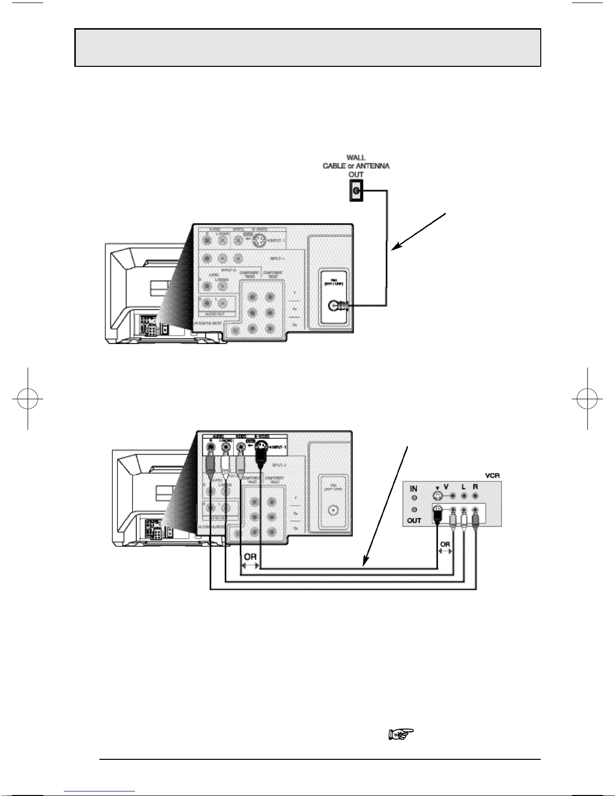
Cable and VCR Connections. . . . . . . 11
Connecting to a DVD Player . . . . . . . 14
Connecting to an External Amplifier . . . 15
Connecting to a Camcorder . . . . . . . 15
Connecting to JVC AVCompu Link . . . 16
GETTING STARTED
Remote Control
Remote Control Basics. . . . . 17
Changing the Batteries. . . . . 17
Remote Programming . . . . . . . . . . 18
CATV and Satellite Codes. . . . . . . . . 18
VCR Codes . . . . . . . . . . . . . . . . 19
DVD Codes . . . . . . . . . . . . . . . . 20
MENU FUNCTIONS
Using the Guide . . . . . . . . . . . . . 21
Plug In Menu
Introduction. . . . . . . . . . 22
Language. . . . . . . . . . . 22
Auto Tuner Setup . . . . . . . 22
Auto Clock Set . . . . . . . . . 23
Manual Clock Set . . . . . . . 24
Finish. . . . . . . . . . . . . . 24
Channel Summary. . . . . . . . . . . . 25
V-Chip. . . . . . . . . . . . . . . . . . . 26
Set Lock Code. . . . . . . . . 33
Picture Settings
Tint . . . . . . . . . . . . . . . 34
Color . . . . . . . . . . . . . . 34
Picture . . . . . . . . . 34
Bright . . . . . . . . . . . . . 34
Detail . . . . . . . . . . . . . 34
Noise Muting . . . . . . . . . 35
Set Video Status . . . . . . . . 35
Sound Settings
Bass . . . . . . . . . . . . . . 36
Treble . . . . . . . . . . . . . 36
Balance . . . . . . . . . . . . 36
MTS (Multi-channel Sound) 36
General Items
On/Off Timer . . . . . . . . . . 37
TV Speaker . . . . . . . . . . 38
Audio Out . . . . . . . . . . . 38
V4 Component-In/
V2 Component-In . . . . . . . 39
Closed Caption . . . . . . . . 39
BUTTON FUNCTIONS
Menu. . . . . . . . . . . . . . . . . . . 40
Exit and PIP Off. . . . . . . . . . . . . . 40
Display . . . . . . . . . . . . . . . . . . 40
Video Status . . . . . . . . . . . . . . . 41
Sleep Timer . . . . . . . . . . . . . . . . 41
Hyper Surround . . . . . . . . . . . . . 41
Muting . . . . . . . . . . . . . . . . . . 41
BBE. . . . . . . . . . . . . . . . . . . . 42
100+ . . . . . . . . . . . . . . . . . . . 42
Return+. . . . . . . . . . . . . . . . . . 42
Input. . . . . . . . . . . . . . . . . . . 42
VCR Buttons . . . . . . . . . . . . . . . 43
DVD Buttons . . . . . . . . . . . . . . . 43
TV/CATV Switch . . . . . . . . . . . . . 43
VCR/DVD Switch . . . . . . . . . . . . . 43
Light. . . . . . . . . . . . . . . . . . . 43
PIP (Picture-In-Picture)
Introduction. . . . . . . . . . 44
On/Move. . . . . . . . . . . . 44
Freeze. . . . . . . . . . . . . 45
Swap. . . . . . . . . . . . . . 45
Channel +/-. . . . . . . . . . 45
Source. . . . . . . . . . . . . 45
APPENDICES
Troubleshooting . . . . . . . . . . . . . 46
Warranty . . . . . . . . . . . . . . . . . 47
Authorized Service Centers . . . . . . . 49
Search Codes. . . . . . . . . . . . . . . 50
Specifications. . . . . . . . . . . . . . . 51
NEW F702/802 mini-IB 3/8/01 11:16 AM Page 10

Connections
1) Connect the antenna or cable TV wire from the wall outlet, in to the RFInput of the two-way splitter.
2) Connect an RF cable from the one of the RFOutputs on the splitter, in to the RF Input on the
back of the VCR.
3) Connect an RF cable from the other the RF Output on the splitter, in to the RF Input on the
back of the TV.
4) Connect the yellow video cable out from the VCR’s Video Output, in to the TV’s Video Input
jack, OR connect an S-Video cable from the VCR’s S-Video output, to the TV’s S-Video input.
5) Connect the white audio cable out from the VCR’s Left Audio Output, in to the TV’s Left Audio
Input Jack.
6) Connect the red audio cable out from the VCR’s Right Audio Output, in to the TV’s Right
Audio Input jack.
• If your VCR is a mono sound unit, it will have only one Audio Out jack. Connect it to the TV’s
Left Audio Input.
• Please consult your VCR’s owner’s manual for more information on its operation.
There are three basic types of antenna or cable connections:
• If you have an antenna or have a cable system that does not require you use a cable box to
select channels, please refer to Diagram #1.
• If you have a cable system that requires the use of a cable box to access all the channels,
please refer to Diagram #2. If you cannot operate your Picture-In-Picture function using Diagram
#2, try the connection shown in Diagram #3. It is possible your cable box allows the signal of only
one channel at a time to be sent to your television.
• If you have a cable system that requires the use of a cable box to access certain premium
channels, but not “basic” cable channels, please refer to Diagram #3.
• For your convenience, connection to a VCR is also shown in the following diagrams. A VCR is
not necessary for operation of the television or Picture-In-Picture (PIP) function. You may omit the
VCR from your connections if you wish.
• For instructions on connecting a VCR only, please see the Quick Setup on page 8.
• For information on using PIP, please see page 44.
•The PIP feature is available on models AV-32F802 and AV-27F802 only.
Cable and VCR Connections
11
Illustration of AV-27F802
Diagram #1
NEW F702/802 mini-IB 3/8/01 11:16 AM Page 11

Connections
12
1) Connect the antenna or cable TV wire from the wall outlet, in to the RFInput of the cable box.
2) Connect an RF cable from the RF Output of the cable box, in to the RF Input on the back of
the VCR.
3) Connect an RF cable from the RF Output of the VCR, in to the RF Input on the back of the TV.
4) Connect the yellow video cable out from the VCR’s Video Output, in to the TV’s Video Input
jack, OR connect an S-Video cable from the VCR’s S-Video output, to the TV’s S-Video input.
5) Connect the white audio cable out from the VCR’s Left Audio Output, in to the TV’s Left Audio
Input Jack.
6) Connect the red audio cable out from the VCR’s Right Audio Output, in to the TV’s Right
Audio Input jack.
•Please see page 44 for information on using the PIP feature with a Cable Box.
• If your VCR is a mono sound unit, it will have only one Audio Out jack. Connect it to the TV’s
Left Audio Input.
• Please consult your VCR’s owner’s manual for more information on its operation.
Cable and VCR Connections - Continued
Illustration of AV-27F802
Diagram #2
NEW F702/802 mini-IB 3/8/01 11:16 AM Page 12

Connections
13
The connection diagrams are intended to show some basic general connections.Some
cable companies may require special connections to properly use your television or
2-tuner PIP function.If you follow these diagrams and either the television or PIP does not
work properly, contact your local cable operator for more connection information. Please
see page 44 for more information on the PIP feature.
Cable and VCR Connections - Continued
1) Connect the antenna or cable TV wire from the wall outlet, in to the RFInput of the two-way splitter.
2) Connect an RFcable from the one of the RFOutputs on the splitter, in to the cable box RF Input.
3) Connect an RFcable from the Cable Box Output, in to the VCR RFInput.
4) Connect an RFcable from the other the RFOutput on the splitter, in to the RFInput on the back of
the TV.
5) Connect the yellow video cable out from the VCR’s Video Output, in to the TV’s Video Input jack, OR
connect an S-Video cable from the VCR’s S-Video output, to the TV’s S-Video input.
6) Connect the white audio cable out from the VCR’s Left Audio Output, in to the TV’s Left Audio Input
jack.
7) Connect the red audio cable out from the VCR’s RightAudio Output, in to the TV’s Right Audio Input
jack.
•Please see page 44 for information on using the PIP feature with a Cable Box.
•If your VCRis a mono sound unit, it will have only one Audio Out jack. Connect it to the TV’s
Left Audio Input.
• Please consult your VCR’s owner’s manual for more information on its operation.
Illustration of AV-27F802
Diagram #3
NEW F702/802 mini-IB 3/8/01 11:16 AM Page 13

Connections
14
1) Connect Green cable out from DVD player “Y”Component Output, in to TV“Y” Component
Input.
2) Connect Blue cable out from DVDplayer “PB”Component Output, in to TV “PB” Component
Input.
3) Connect Red cable out from DVDPlayer “PR”Component Output, in to TV “PR” Component
Input.
4) Connect White Audio cable out from DVD Left Audio Output, in to TV Left Audio Input 2.
5) Connect Red Audio cable out from DVDRight Audio Output, in to TV Right Audio Input 2.
•Green, blue and red are the most common colors for DVD cables. Some models may vary
colors, please consult the user’s manual for your DVD Player for more information.
•Be careful not to confuse the red DVD cable with the red audio cable. It is best to complete
one set of connections (DVD or Audio Output) before starting the other to avoid accidentally
switching the cables.
•See page 20 for instructions on programming your remote control to operate the basic func-
tions of your DVD player.
•AV-32F802 & AV-27F802: You may also connect the DVD player to Input 4. If you use Input 4
for the DVD connection, you must set the V4 COMPONENT-IN on the initial Setup Menu to
“YES” for proper display of the DVD signal.
•AV-32F702 & AV-27F702: If you use Input 2 (Component-In) for the DVDconnection, you
must set the V2 COMPONENT-IN on the initial Setup Menu to “YES” for proper display of the
DVD signal.
•NOTE: Progressive DVD Players (players with an output scan of 31.5 KHz) will not work prop-
erly with this television.
Connecting to a DVD player
Illustration of AV-27F802
NEW F702/802 mini-IB 3/8/01 11:16 AM Page 14

Connections
15
1) Connect the yellow video cable out from the Camcorder’s Video Output, in to the TV’s Video
Input jack, OR connect an S-Video cable from the Camcorder’s S-Video output, to the TV’s
S-Video Input.
2) Connect the white audio cable out from the Camcorder’s Left Audio Output, in to the TV’s Left
Audio Input jack.
3) Connect the red audio cable out from the Camcorder’s Right Audio Output, in to the TV’s
Right Audio Input jack.
•If your Camcorder is a mono sound model it will have only one audio jack. Connect it to the
TV’s Left Audio jack.
Connecting to an External Amplifier
Connecting to a Camcorder
1) Connect the white audio cable from the TV’s Left Audio Output jack to the Amplifier’s Left
Audio Input jack.
2) Connect the red audio cable from the TV’s Right Audio Output jack to the Amplifier’s Right
Audio Input jack.
• See also “TV Speaker” and “Audio Out” on page 38 for more information on using external
speakers.
You may connect a camcorder to your television by using the front Input Jacks (Input 3)
located under the front panel door. To access, press lightly on the door to open it. You may also
connect a game console or other equipment using these jacks. Camcorders may also be
connected to the television’s rear input jacks.
Illustration of AV-27F802
NEW F702/802 mini-IB 3/8/01 11:16 AM Page 15

Connections
16
To Connect: Plug one end of the AVCompu Link cable into the AVCompu Link input on your VCR,
DVD, or other Compu Link device. Plug the other end of the AV Compu Link cable into the AVCompu
Link input at the rear of the television.
Connecting to JVC AV Compu Link
JVC’sAV Compu Link feature makes playing video tapes or DVDs totally automatic. Simply insert
a pre-recorded tape* into your JVC-brand VCR or DVD into your JVC DVD player and the device
will automatically turn on and begin playback. At the same time, using the AV Compu Link, the
VCR or DVD player sends a signal to the television telling it to turn on and switch to the proper
video input
• The AV Compu Link cable may be included with the JVC AVCompu Link accessory you wish to
connect.If it is not, contact an authorized JVC Service Center for part # EWP 805-012.
• AV Compu Link can only be used with JVC-brand products.
NOTES:
* In order for theVCRplayback to begin automatically, the recording tabs must beremoved from the
VHStape.If the tab is in place, automatic switching will occur when you push theVCR’s PLAYbutton.
• The AV Compu Link cable has a male 3.5mm (mono) plug on each end.
• If your JVC-brand VCR has “A Code/B Code RemoteControl Switching”(see yourVCR’s instruction
book), usingVCR A Codewill switch theTV to input 1.
• To connect a JVC HiFi receiver or amplifier for a completely automated home theater, see the HiFi’s
connection instructions for detailed connection information.
• AV COMPU LINK EX is compatible with the following receivers:RX-664V, RX-665V, RX-668VBK,
RX-774V, RX-778VBK, RX-884V, RX-888VBK, RX-1024V, RX-1028VBK, and later receiver models.
Illustration of AV-27F802
NEW F702/802 mini-IB 3/8/01 11:16 AM Page 16

Remote Control
17
Before you can operate the remote control, you must first install
the batteries (included). See “Changing the Batteries” at the
bottom of this page for instructions. (For an illustration, please see
page 7.)
Press the POWER button to turn the television on or off.
Make sure the TV/CATV switch is set to TV. Move the switch to
CATV only if you need to operate a cable box.
Slide the VCR/DVD selector switch to VCR to control a VCR,
slide to DVDto control a DVD player. Please see pages 18 to
20 for instructions on programming your remote control to
operate a Cable box, VCR or DVDplayer.
Press the CH+ and CH- buttons to scan through the channels.
Tap the CH+ or CH- button to move through the channels one
channel at a time.
To move rapidly through the channels using JVC’s Hyperscan
feature, press and hold CH+ or CH-. The channels will zip by at
a rate of five channels per second.
Press VOL+ or VOL -to raise or lower the volume. An indicator
bar will appear onscreen to show you the television volume
level.
The CH+/- and VOL+/- buttons are also used to navigate JVC’s
onscreen menu system.
You can directly access specific channels using the 10-key pad.
For more information on remote control button features, see
pages 40 to 45. For information on using the onscreen menus,
see page 21.
Changing the Batteries
Push down on the remote’s back cover and slide towards the bottom to remove it.
Insert two AAbatteries (supplied), carefully noting the "+" and "-" markings on the batteries and on
the remote control. To avoid a potential short circuit, insert the "-" end first. Be sure to use only size
AA batteries.
When batteries are installed, slide the cover back into place (until it clicks into position).
• If the remote control acts erratically, replace the batteries. Typical battery life is six months to one
year. We recommend using alkaline batteries for longer battery life.
Whenyou changethe batteries,trytocomplete the task within threeminutes.If you takelongerthanthree
minutes,the remote control codes for yourVCR, DVD,and/or CableBox may have to be reset (see page18-20).
Remote Control Basics
•
•
•
•
•
•
•
•
•
•
Notes: Remote control model RM-C301G is shown at the left.
A different model remote control may have come with your
television.
NEW F702/802 mini-IB 3/8/01 11:16 AM Page 17

Remote Programming
18
Setting the CATV,VCR and DVD Codes
You can program your remote to operate your cable box, satellite receiver, VCR or DVD
player by using the instructions and codes listed below. If the equipment does not respond to any
of the codes listed below or to the code search function, use the remote control supplied by the
manufacturer.
Cable Box or Satellite codes
The remote control is programmed with CATV and/or Satellite codes for power on, power off,
channel up, channel down, and 10 key operation.
1) Find the CATV/Satellite brand from the list of codes shown below.
2) Slide the 2-way selector switch to “CATV”.
3) Press and hold down the DISPLAY button.
4) With the DISPLAY button held down, enter the first code number listed using the 10 key pad.
5) Release the DISPLAY button.
6) Confirm the operation of the Cable Box/Satellite receiver.
•If your CATV or Satellite box does not respond to the first code, try the others listed. If it does not
respond to any code, try the Search Codes Function, on page 50.
NEW F702/802 mini-IB 3/8/01 11:16 AM Page 18

Remote Programming
19
VCR codes
The remote control is programmed with VCR codes for power on, power off, play, stop, fast-forward,
rewind, pause, record, channel up, and channel down operation.
1) Find the VCR brand from the list of codes shown below.
2) Slide the first 2-way selector switch to “TV” and the other 2-way selector switch to “VCR”.
3) Press and hold down the DISPLAY button.
4) With the DISPLAY button held down, enter the first code number listed with the 10 key pad.
5) Release the DISPLAY button.
6) Confirm the operation of the VCR.
• If your VCR does not respond to the first code, try the others listed. If it does not respond to any
code, try the Search Codes Function, on page 50.
• Some manufacturer’s VCR’s may not respond to the TV/VCR button, even if other buttons work properly.
• To record, hold down the REC button on the remote and press PLAY.
NEW F702/802 mini-IB 3/8/01 11:16 AM Page 19

Remote Programming
20
DVD codes
The remote control is programmed with DVD codes for power on, power off, play, stop,
fast-forward, rewind, previous chapter, next chapter, tray open/close, and still/pause operation.
1) Find the DVD player brand from the list of codes shown below.
2) Slide the first 2-way selector switch to “TV” and the other 2-way selector switch to “DVD”.
3) Press and hold down the DISPLAY button.
4) With the DISPLAY button held down, enter the first code number listed with the 10 key pad.
5) Release the DISPLAY button.
6) Confirm the operation of the DVD player.
• If your DVD player does not respond to the first code, try the others listed. If it does not respond
to any code, try the Search Codes Function, on page 50.
•After you program your remote, some DVD buttons may not work properly. If some buttons do not
work properly, use the remote control which came with your DVDplayer.
NEW F702/802 mini-IB 3/8/01 11:16 AM Page 20
Other manuals for I' Art AV-27F702
1
This manual suits for next models
4
Table of contents
Other JVC TV manuals