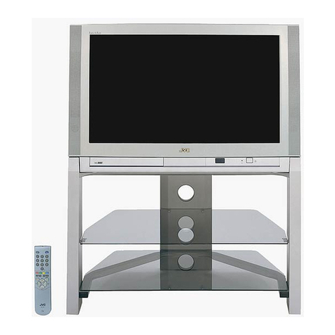
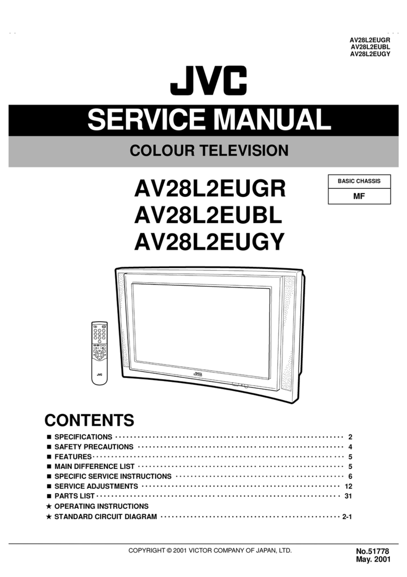
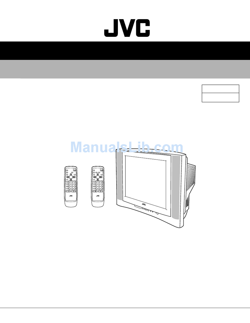
JVC AV32 X25EUS User manual

No.51994
AV32X25EUS / AV32X250EU
S
AV32X25EIGY / AV32X25EKG
Y
AV28X25EUS / AV28X25EIG
Y
AV28X25EKG
Y
1COPYRIGHT © 2002 VICTOR COMPANY OF JAPAN, LTD.
Jun. 2002
AV32X25EUS / AV32X250EUS
AV32X25EIGY / AV32X25EKGY
AV28X25EUS / AV28X25EIGY
AV28X25EKGY
CONTENTS
!SPECIFICATIONS ・・・・・・・・・・・・・・・・・・・・・・・・・・・・・・・・
・・・・・・・・・・・・・・・・・・・・・・・・・・・・・・・・・・・・・・・・・・・・・・・・・・・・・・・・・・・・・・・・
・・・・・・・・・・・・・・・・・・・・・・・・・・・・・・・・・・・・・・・・・・・・・・・・・・・・・・・・・・・・・
・・・・・・・・・・・・・・・・・・・・・・・・・・・・・・・・・・・・・・・・・・・・・・・・・・・・・・・・・・
・・・・・・・・・・・・・・・・・・・・・・・・・・・・・ 2
!SAFETY PRECAUT IONS ・・・・・・・・・・・・・・・・・・・・・・・・・・・・・・・・
・・・・・・・・・・・・・・・・・・・・・・・・・・・・・・・・・・・・・・・・・・・・・・・・・・・・・・・・・・・・・・・・
・・・・・・・・・・・・・・・・・・・・・・・・・・・・・・・・・・・・・・・・・・・・・・・・・・・・・・・
・・・・・・・・・・・・・・・・・・・・・・・・・・・・・・・・・・・・・・・・・・・・・・
・・・・・・・・・・・・・・・・・・・・・・・ 4
!FEATURES・・・・・・・・・・・・・・・・・・・・・・・・・・・・・・・・
・・・・・・・・・・・・・・・・・・・・・・・・・・・・・・・・・・・・・・・・・・・・・・・・・・・・・・・・・・・・・・・・
・・・・・・・・・・・・・・・・・・・・・・・・・・・・・・・・・・・・・・・・・・・・・・・・・・・・・・・・・・・・・・・・
・・・・・・・・・・・・・・・・・・・・・・・・・・・・・・・・・・・・・・・・・・・・・・・・・・・・・・・・・・・・・・・・
・・・・・・・・・・・・・・・・・・・・・・・・・・・・・・・・・・・
・・・・・・
・・・ 6
!MAIN DIFFERENCE LIST ・・・・・・・・・・・・・・・・・・・・・・・・・・・・・・・・
・・・・・・・・・・・・・・・・・・・・・・・・・・・・・・・・・・・・・・・・・・・・・・・・・・・・・・・・・・・・・・・・
・・・・・・・・・・・・・・・・・・・・・・・・・・・・・・・・・・・・・・・・・・・・・・・・・・・・・・・
・・・・・・・・・・・・・・・・・・・・・・・・・・・・・・・・・・・・・・・・・・・・・・
・・・・・・・・・・・・・・・・・・・・・・・ 6
!FUNCTIONS ・・・・・・・・・・・・・・・・・・・・・・・・・・・・・・・・
・・・・・・・・・・・・・・・・・・・・・・・・・・・・・・・・・・・・・・・・・・・・・・・・・・・・・・・・・・・・・・・・
・・・・・・・・・・・・・・・・・・・・・・・・・・・・・・・・・・・・・・・・・・・・・・・・・・・・・・・・・・・・・・・・
・・・・・・・・・・・・・・・・・・・・・・・・・・・・・・・・・・・・・・・・・・・・・・・・・・・・・・・・・・・・・・・・
・・・・・・・・・・・・・・・・・・・・・・・・・・・・・・・・・・
・・・・
・・ 7
!SPECIFIC SERVICE INSTRUCTIONS ・・・・・・・・・・・・・・・・・・・・・・・・・・・・・・・・
・・・・・・・・・・・・・・・・・・・・・・・・・・・・・・・・・・・・・・・・・・・・・・・・・・・・・・・・・・・・・・・・
・・・・・・・・・・・・・・・・・・・・・・・・・・・・・・・・・・・・・・・・・・・・・
・・・・・・・・・・・・・・・・・・・・・・・・・・
・・・・・・・・・・・・・ 8
!SERVICE ADJUSTMENTS ・・・・・・・・・・・・・・・・・・・・・・・・・・・・・・・・
・・・・・・・・・・・・・・・・・・・・・・・・・・・・・・・・・・・・・・・・・・・・・・・・・・・・・・・・・・・・・・・・
・・・・・・・・・・・・・・・・・・・・・・・・・・・・・・・・・・・・・・・・・・・・・・・・・・・・・
・・・・・・・・・・・・・・・・・・・・・・・・・・・・・・・・・・・・・・・・・・
・・・・・・・・・・・・・・・・・・・・・ 14
!PARTS LIST ・・・・・・・・・・・・・・・・・・・・・・・・・・・・・・・・
・・・・・・・・・・・・・・・・・・・・・・・・・・・・・・・・・・・・・・・・・・・・・・・・・・・・・・・・・・・・・・・・
・・・・・・・・・・・・・・・・・・・・・・・・・・・・・・・・・・・・・・・・・・・・・・・・・・・・・・・・・・・・・・・・
・・・・・・・・・・・・・・・・・・・・・・・・・・・・・・・・・・・・・・・・・・・・・・・・・・・・・・・・・・・・・・・・
・・・・・・・・・・・・・・・・・・・・・・・・・・・・・・・・・
・・
・33
★
OPERATING INSTRUCTIONS
★
STANDAR D CIRCUIT DIAGRAM ・・・・・・・・・・・・・・・・・・・・・・・・・・・・・・・・
・・・・・・・・・・・・・・・・・・・・・・・・・・・・・・・・・・・・・・・・・・・・・・・・・・・・・・・・・・・・・・・・
・・・・・・・・・・・・・・・・・・・・・・・・・・・・・・・・・・・・・・・・・・・・・・・・
・・・・・・・・・・・・・・・・・・・・・・・・・・・・・・・・
・・・・・・・・・・・・・・・・2- 1
SERVICE MANUAL
COLOUR TELEVISION
BASIC CHASSIS
MFⅡ
ⅡⅡ
Ⅱ

No.51994
A
V32X25EUS / AV32X250EUS
A
V32X25EIGY / AV32X25EKGY
A
V28X25EUS / AV28X25EIGY
A
V28X25EKGY
2
SPECIFICATIONS
Content
Item
AV 32 X25E US / AV3 2X2 50 EUS / AV2 8X2 5E US AV 32 X2 5EIG Y / AV 28 X2 5EIG Y
AV 32 X2 5EKGY / AV 28X 25 EKGY
(
32 ”
)
: 85. 5cm×55.0cm×56 .8c m
(
32”
)
: 85. 5cm×55.0cm×56 .8cmDimensions ( W×
××
×H×
××
×D )
( 28 ”) : 78. 0cm ×50.9cm×49 .9c m (28”) : 78. 0cm×50.9cm
×49 .9cm
Mass (32 ”) : 54. 2 kg / (28” ) : 40. 2kg (32”) : 54. 2kg / (28” ) : 40. 2kg
TV RF System CCI R ( B /G, D/ K, L , L’,I) CCI R ( I )
Co lour Sy stem PA L / SECA M / NTSC (Only in EXT mo de ) PA L / NTSC (On ly in EXT mod e)
St ere o Sy stem A2 (B /G, D/ K) / NICAM (B/G , I, D/K, L) NICAM ( I )
Teletext System Fastext (UK system) / TOP (German system)
WST(world s tandard system)
Fastext (UK system)
WST(world s tandard system)
VHF : 47MHz ~470MHz VHF : 47MHz ~470MHz ( EI model )
UHF : 4 7 0MHz ~86 2MHz UHF : 47 0MHz ~862MHz ( EK / E I model )
Receiving Frequency
•Fr ench c abl e TV c han n el of br oa dcas t
fr eq ue ncies 1 16~1 72MH z & 220~46 9MHz
VIF Carrier : 38.9MHz(B/ G, D/ K, I, L) / 33.95MHz VIF Carrier : 3 8. 9MHz
SIF C arr ier : 33 .4M Hz( 5.5 MHz : B/G ) SIF Carrier : 32.9MHz(6.0MHz )
32 .9 MHz(6. 0M Hz : I )
Intermediate Frequency
32 . 4 MHz( 6. 5MHz : L, D/K)
40.45MHz (6.5MHz : L’)
PAL : 4. 43 MHz PAL : 4. 43 MHz
SE CAM : 4.40625MHz / 4.25MHz
Colour Sub Carrier Freq.
NT SC : 3.58MHz / 4.43MHz NT SC : 3.58MHz / 4.43MHz
Power Input AC 2 20V~2 40V , 5 0Hz
Power Consumption (32") ( 28 ” ) ( 32") (28”)
Aerial Input Term 75 Ωun ba lanc ed, Coaxi al
( 32 ”) : V iewab l e ar e a 7 6cm ( m eas ur ed diag on all y)
(
32”
)
: V i ewab l e ar e a 7 6cm
(
meas ur ed dia
g
on all
y)
Pictur e Tube
( 28 ”) : V iewab l e ar e a 6 6cm ( m eas ur ed diag on all y)
(
28”
)
: V i ewab l e ar e a 6 6cm
(
meas ur ed dia
g
on all
y)
Hi g h Vo lt age 31.0kV (at zerobeamcurrent)
Spe ake r 13 cm ×6.5cm, Oval type×2
Au dio Output 7.5 W + 7.5 W
EX T-1 /EXT- 2/E XT- 3 ( I N/ OUT) 21 -p in E ur o c onn ecto r ( SC ART so cket) ×3
Vide o : Vp-p 75Ω( RCA pin ja ck)
Au dio (L /R ) : 50 0m Vr ms(-4d Bs) , High Im pe dan ce (RC A p in j ac k)
S / Video Y : 1V p- p P OSITI VE ( Neg at ive sync Pr ovide d, wh en te rmi nat ed wit h 7 5Ω)
EXT-4 (Input)
C : 0 .3V p- p ( B urst sign al , wh en term in at ed w ith 7 5Ω
)
AUDIO OUT (Variable) 0~1Vrms, Low Impedance (RCA pin jack×2)
Headphone jack St er eo min i j ac k ( φ3.5mm )
Remote Control Unit RM-C54 ( AAA/ R03 dry cell batt ery×2) RM-C55 (AAA/R03 dry cell b att ery×2)
Design & sp eci fications ar e su bje ct to change wi thout no tice.
+1.0kV
-1. 5kV
178W (Max)
125W (Avg)
187W (Max)
132W (Avg)
178W (Max)
125W (Avg)
187W (Max)
132W (Avg)

No.51994
A
V32X25EUS / AV32X250EU
S
A
V32X25EIGY / AV32X25EKGY
A
V28X25EUS / AV28X25EIGY
A
V28X25EKGY
3
■
■■
■21-pin Euro connector (SCART socket) : EXT-1 / EXT-2 / EXT-3
(P-P= Peak to Peak, B-W= Blanking to white peak)
Pin
No . Signal Designation Matching Value EXT-1 EXT-2 EXT-3
1 AU DIO R o ut put 50 0m Vr ms( Nom ina l),
Low impedance
○
(TV OUT)
○
(LINE OUT) NC
2 AU DIO R in put 50 0m Vrms( Nom ina l),
Hig h impe da nce ○○○
3 AU DIO L o utp ut 50 0m Vrms( Nom ina l),
Low impedance
○
(TV OUT)
○
(LINE OUT) NC
4 AUDIO G ND ○○○
5 GND (B) ○○○
6 AUDIO L input 500mVrms(Nominal),
Hig h impe da nce ○○○
7Binput 700mV
B- W , 75Ω○○NC
8 FUNCTON SW
(SLOW SW)
Low : 0-3V, High : 8-12V, High
impedance
○○○
9 GND (G) ○○○
10 SCL3 NC ○NC
11 G in put 70 0mVB- W , 7 5Ω○○NC
12 SDA3 NC ○NC
13 GND (R) ○○○
14 GND (YS)○○NC
15 R / C input R : 700mVB- W , 75Ω
C : 300mVP- P , 75Ω
○
(only R)
○○
(only C)
16 Ys in put Low : 0 - 0.4, High : 1 - 3V, 75Ω○ ○ NC
17 GND(VIDEO output) ○○○
18 GND(VIDEO input) ○○○
19 VIDEO ou tpu t 1V P- P( Nega tive g oin g sync ), 75 Ω○
(TV)
○
(LINE OUT) NC
20 VIDEO / Y input 1VP- P( Nega tive g oi n g sync ), 75 Ω○ ○ ○
21 COMMON G ND ○○○
[Pin assignment]

No.51994
A
V32X25EUS
A
V32X250EUS
A
V28X25EUS
4
SAFETY PRECAUTIONS
1. The d esi gn of th is pr od uct con ta in s sp ecial har d wa re , ma ny
circuit s and components specially for safety purposes. For
con ti nu ed pr ot ection , n o chan g es sh ou ld b e ma de to the o rig i nal
d esign un less a uth or ized in w ri tin g by th e ma nu fact ur er .
Rep l acemen t p ar ts must b e i d ent ic al to thos e u sed i n th e or igi n al
circu it s. S er vi ce sho uld b e p er for med by qu al if i ed p ers on nel
on ly.
2. Al te r ation s of t he desi g n or ci rcui tr y of t he pr od ucts sh ould not be
made. Any design alterations or additions will void the
m anu fact ur er 's warr a nt y and w ill f ur th er r eli eve t he ma nu factu rer
of r esp onsib ili ty for per so na l i njur y or p r op erty d am ag e r esult in g
th er efr om .
3. M an y e l ectr ical an d m ech anica l p ar ts in th e pr od ucts ha ve
special safety-related characteristics. T hese characteristics are
oft en no t e viden t f r om vi sua l insp ection n or ca n t he pr o tect io n
aff or de d by th em nece ssar ily b e ob tain ed b y u sin g r ep lacem en t
com po ne nts ra ted f or hig he r vo l tag e, w att ag e, etc. R ep lacem en t
p arts wh ic h ha ve th ese sp eci al s afet y ch ar act er ist ics ar e
identified in the parts list of Servic e manual. El ec tric al
components having su ch features are identified by shading
on the sche matic s and by (!
!!
!) on the parts list in Service
manual. The us e of a sub sti tu te r ep la cem en t w hich do es n ot
h ave th e same saf ety ch ar act er ist ics as t he r eco mmen de d
r eplac em ent par t sh ow n in th e p ar ts list of S er vice m an ual m ay
cause shock, fire, or other hazards.
4. Do n't short between the LIVE side ground and ISOL ATED
(NEUTRAL) side ground or EARTH side ground when
repairing.
Some model's power circuit is partly different in the GND. The
diff er enc e of th e G ND is sho wn b y th e LIV E : (") side GND, the
ISO LATE D( NEUTRAL) : ( #) side G ND and EARTH : ($) side
GN D. D o n't sh or t b et we en th e LIV E sid e GND an d
ISO LATE D(NEUTRAL) side GND or EARTH side GND and
n ever m ea sur e w it h a m ea suri ng a ppa ratus ( oscillo scop e etc.)
th e LI VE sid e GND an d IS OLA TED(NE UTRAL ) sid e G ND or
EARTH side GND at the s ame time.
If above note will not be kept, a fuse or any parts will be broken.
5. If any repair has been made to the chassis, it is recommended
th at t he B1 set ting shou ld b e ch ecke d or adj u ste d ( Se e
ADJUSTM ENT OF B 1 POWE R SU PPLY) .
6. The hi gh vol ta ge app lie d t o th e pi ctu r e tu be mu st con for m wit h
th at sp ecifi ed in S er vice m an ual. E xcessive h igh vo lt ag e ca n
cau se an incr e ase i n X- Ray em issi on , ar cing an d possi b le
component damage, therefore operation under excessive high
voltage conditions should be kept to a minimum, or should be
preve nt ed. If s ever e arc in g occurs, rem ove t he AC power
imm ed iate ly an d de ter mi ne th e ca use b y vi sua l i nsp ect io n
( in corr ect in stal lat ion, cr acke d or m elte d high vo lt age har n ess,
p oor so ld eri ng, et c.). To m aint ai n the p r ope r min imu m l e vel of
sof t X-R ay emi ssion, c omp on en ts i n th e high voltag e ci rcui tr y
incl ud ing t he pict ur e tu be must b e t he e xact rep lacem e nts or
alte rn at ives ap prove d b y th e ma nuf act ur er of th e c om plet e
pr od uct.
7. Do n ot c hec k high volt ag e b y drawing an arc. Use a high volt ag e
m eter or a hig h v oltag e pr ob e wi t h a V TVM. D ischa rg e th e
picture tube before attempting meter connection, by connecting
a cl ip le ad to th e gr ou nd f ra me a nd c onn ecti n g th e oth er end of
the lead through a 10kΩ2W resisto r to the an od e b utt on .
8. W hen se r vi ce i s r equ ir e d, ob ser ve th e or igi na l lea d dr ess. E xtr a
pr ec aut i on sh ou ld b e g ive n t o assur e cor r ect l ea d dress in th e
hig h voltag e cir cuit a r ea. W her e a s hor t ci rcui t h as occu rr e d,
th ose co mp on ent s tha t indica te evide nce of ove r hea ting sho uld
b e r e place d. A l wa ys u se th e ma nuf act ur er's r ep lacem en t
components.
9. Isolation Check
(Safety for Electrical Shock Hazard)
Af ter r e-ass emb lin g th e p rodu ct, al ways per f orm an i sol at io n
ch eck on the expo sed me tal p ar ts of t he cabi n et ( a nte nn a
ter m ina ls, vid eo /au dio i npu t and ou tpu t t er min als, Con tr ol kn obs,
m etal cabin et, screw he ad s, ea r ph one jack, con tr ol shaf ts, etc.)
to be su re th e p r odu ct is s af e t o o pe r ate with ou t d an ger of
elect rical shoc k.
(1) Dielectric Strength Test
The iso lati on be tw een the A C prim a ry ci rcu i t an d al l me tal p arts
exp ose d t o th e us er , p ar ticular ly an y e xp os ed met al p art h avi ng a
r etu rn p ath to t he chass is sho ul d withs tan d a volt age of 3 000 V
AC (r.m.s.) for a period of one second.
( . . . . W it hstan d a vo lt ag e of 1 10 0V A C ( r.m. s.) t o an ap pl ianc e
r ate d up to 12 0V , an d 3 00 0V AC ( r.m. s.) to an ap plian ce r at ed
200V or more, for a period of one second.)
This method of test requires a t est equipment n ot generally found
in t he servic e trad e.
(2) Leakage Current Check
Pl ug th e A C lin e c ord d ir ect l y in to th e A C ou tlet ( d o n ot use a lin e
isol ati o n transf or m er du r in g this ch eck.). U sin g a " Lea kag e
Cur r ent T este r", me asure th e l ea kag e cu rre nt f rom each exp osed
m etal p ar t of the ca bine t, p art icu l arl y any e xpos ed me tal p ar t
h aving a r e turn pa th to t he ch assis , t o a kn own go od ea rt h
gr ou nd (wa ter pi p e, e tc.) . An y leaka ge cur ren t m ust n ot e xceed
0.5mA AC (r.m.s.).
How eve r, in trop ic al ar ea , th is mu st no t exce ed 0.2 mA AC
(r.m.s.).
"
""
"Alte rnat e Che ck M et ho d
Pl ug th e A C lin e c ord d ir ect l y in to th e A C ou tlet ( d o n ot use a lin e
isol ati o n tr an sfor mer dur ing t hi s che ck.) . U se an AC vo lt me ter
h aving 1 00 0 oh ms pe r volt or m ore sens it ivity in th e fo llow ing
m ann er. Con nec t a 1 50 0Ω10W res ist or para lle le d b y a 0 .1 5µF
AC -type c apa cit or bet we en an expo sed met al pa rt a nd a kno wn
g ood e ar th gr o un d ( wa ter pipe , etc.) . M eas ur e th e A C vo lt ag e
acr oss th e res ist or w ith th e AC vo ltm eter. M ove th e resistor
con nec tion to e ach exp ose d me tal par t, p art icular ly a ny exp osed
m etal p ar t havi n g a r etu rn pat h to t he ch assi s, an d m easu re th e
AC vol tag e ac ro ss the r es ist or . N o w, re ver se th e pl u g in th e AC
ou tl et and r e pe at eac h m ea sur em en t. An y vol t ag e me asu re d
must not exc eed 0.75V AC (r.m.s.). This c orresponds to 0.5mA
AC (r.m.s.).
Howeve r, in tropica l area, this must not exceed 0.3V AC ( r.m. s.).
This corresponds to 0.2mA AC (r.m.s.).
0.15μF AC-T YPE
1500 Ω10W
GOODEARTH GROUND
PLACE THIS PROBE
ON E A CH EX PO SE D
ME T AL PA RT
ACVOLTMETER
(HAVING 1000 Ω/V,
OR MOR E SENSIT IVITY)
AV32X25EUS / AV32X250EUS / AV28X25EUS
No.51994
A
V32X25EIGY / AV32X25EKGY
A
V28X25EIGY / AV28X25EKGY
5
SAFETY PRECAUTIONS
1. The d esign of this pr o du ct c ont ains spe ci al har d wa re and ma ny
circuit s and components specially for safety purposes. For
con ti nu ed pr ot ection , n o chan g es sh ou ld b e ma de to the o rig i nal
d esign un less a uth orized in writin g by th e ma nu fact ur er .
Rep l acemen t p ar ts must b e i d ent ic al to thos e u sed i n th e or igi n al
circu it s. S er vi ce sho ul d b e p er for m ed by qu alif i ed p ers on nel
on ly.
2. Al te r ation s of th e desi g n or circ ui tr y of th e pr od uct sho ul d no t b e
made. Any design alterations or additions will void the
m anu fact ur er 's warr a nt y and w ill f ur th er r eli eve t he ma nu factu rer
of r esp onsib ili ty for per so na l i njur y or p r op erty d am ag e r esult in g
th er efr om .
3. M an y electr ical a nd me cha nical p ar ts i n the pr od uct h ave spe cial
saf ety- relat ed ch aract erist ics. Thes e ch aracteristics a re oft en not
evid ent from vi su al i nsp ectio n no r c an th e p r otect ion af forde d by
th em n ecess ar y b e o bta in ed by usi ng r e plac em ent c om pon en ts
r ate d for hi gh er vol ta ge, wa tta ge , etc. Re placemen t p art s wh ic h
h ave th ese spe cial saf et y c har ac ter istic s ar e id ent if ied in th e
Pa rts List of S er vice Ma nu al. El ectr ical co mp on en ts h aving suc h
fe atur es ar e i de ntifi ed b y sh ad in g on th e sche ma tic s a nd by ( !)
on t he P ar ts List in the S ervice Man ual. The u se of a sub stitut e
r eplac em ent w hich d oes no t h ave th e s am e saf ety
ch ar acter istics as the r e comm end ed r eplace m ent p ar t sho wn in
th e P ar ts List of Se rvice M an ual m ay cau se sh ock, f ire, or ot her
hazards.
4. The l ea ds in th e p rodu cts ar e r ou ted an d d r essed wit h t ies,
clam ps, tu bing ’ s, b ar ri e rs a nd t he like t o be s epa ra ted fr om l ive
p arts, h ig h t em pe ra tur e pa rts, m oving par ts an d / or sh ar p ed ge s
for t he p r even tion of e lectr ic sh ock and fi re h azar d. W he n
ser vi ce is re qu ired , the or igi n al le ad r outi n g and d re ss sh ou ld b e
ob ser ved , and it sh ould b e co nfi rmed t hat th ey h ave b ee n
r etu rn ed to no rm al, aft er r e- asse mb li n g.
WARNING
1. The eq uipm e nt h as b ee n d esi g ned a nd m anu fact ur ed to me et inte rn ati o nal saf ety sta nd ar ds.
2. It is t he l eg al resp onsib ili ty o f th e re pa ir er t o e nsur e th at t hes e s afet y sta nd ards ar e m aint ai ne d.
3. Rep ai rs mu st b e m ad e i n acc or dan ce with th e r ele vant saf ety st an dar ds .
4. It is essen tial t hat saf ety critical c omp on ent s ar e r eplac ed by a pp ro ved pa rt s.
5. If main s volt ag e sel ec tor i s p r ovide d, ch eck s ettin g f or l oca l vo ltag e.
AV 32 X2 5EIG Y / AV 32 X2 5EKGY
AV 28 X2 5EIG Y / AV 28 X2 5EKGY

No.51994
A
V32X25EUS / AV32X250EUS
A
V32X25EIGY / AV32X25EKGY
A
V28X25EUS / AV28X25EIGY
A
V28X25EKGY
6
FEATURES
"New chassis d esign ena bl e us e of an in terac tive on scr een
control.
"The TELETEXT SYSTEM has a built-in FASTEXT (UK system),
TOP (German system) and WST (world standard s yst em)
system.
"Be caus e th is T V un it cor resp on ds t o m ultipl e x br oa dca st, u ser s
can enjoy music programs and sporting events with live realism.
In ad di ti on , BI LINGUAL pro gr am s can b e h ear d in th ei r or ig in al
language.
"Users can make VCR dubbing of picture and sound by controlling
th e AV se l ecto r t o s el ect a n opt i on al s our ce at t he E XT-2 ou tpu t
sh own in figu re.
MAIN DIFFERENCE LIST
!
ModelName
Part Name
AV 32 X2 5E US
AV 32 X2 50E US
AV 32 X2 5EIG Y
AV 32 X2 5EKGY AV 28 X2 5E US
AV 28 X2 5EIG Y AV 28 X2 5EKGY
MA IN PW B AS SY SMF-1404A-U2 SMF-1 944A-U2 SMF-1403A-U2 SMF-1943A-U2
POW E R & DEF PW B AS SY SMF-2 40 4A-U2 SMF-2 40 3A-U2
CRT SOCKE T PWB AS SY SMF-3 40 4A-U2 SMF-3 40 3A-U2
FRONT CONTROL PWB ASSY
SMF-8404A-U2 SMF-8403A-U2
SIDE CONTROL PWB AS SY SMF-8104A-U2 SMF-8 103A-U2
!IT C TUBE W 76 ERF0 42 X04 4 W 66 QD E993 X9 25
!DEGA US SING C OI L QQW 0 066 -0 01 QQW 0 100 -0 01
!ROTATIO N CO IL QQW0 130 -0 01
!FBT QQH0 127 - 001 QQH0 126 - 001
!REAR C OVE R LC1 131 6- 00 1A- U LC1 128 2- 00 1C-U
CUS HION AS SY LC1 137 3- 00 2A- U LC1 131 8- 00 2A- U
PA CK ING CASE AE M1 002 -07 9-E AE M1 002- A76-E
COR NE R POST AE M3 119- 003A- E
!ModelName
Part Name
AV 32 X2 5E US
AV 32 X2 50E US
AV 32 X2 5EIG Y
AV 32 X2 5EKGY AV 28 X2 5E US AV 28 X2 5EIG Y
AV 28 X2 5EKGY
!FR ONT CA BIN ET AS SY LC1 136 0- 00 4A- U LC1 136 0- 00 3A- U LC1 131 3- 00 4B- U LC1 131 3- 00 3B- U
!POWER CORD QMPK160-185-JC QMPN130-185-JC QMPK160-185-JC QMPN130-185-JC
JVC M AR K LC4 125 0- 00 2C-C LC4 125 0- 00 1C-C LC4 125 0- 00 2A- C LC4 125 0- 00 1C-C
REMOTE CONTROL UNIT RM-C54H-1C RM-C55H-1C RM-C54H-1C RM-C55H-1C
!
ModelName
Part Name
AV32X25EU S AV32X250EUS AV32X25EIG Y AV32X25EKGY AV28X25EU S AV28X25EIG Y AV28X25EKGY
!INST BOOK
LC T11 84-00 1A- U
LC T11 85-00 1A- U
LC T11 86-00 1A- U
LC T11 85-00 1A- U LC T11 87-00 1A-U
LC T11 84-00 1A- U
LC T11 85-00 1A- U
LC T11 86-00 1A- U
LC T11 87-00 1A- U
!RATING LABEL LC1 141 4-00 3A- U LC1 137 2-00 4A-U LC1 136 4-00 8A-U LC1 136 4-00 7A-U LC1 141 4-00 4A-U LC1 136 4-01 0A-U LC1 136 4-00 9A-U
EURO LABEL AEM1064-017-U AEM1064-020-U AEM1064-019-U AEM1064-018-U AEM1064-021-U AEM1064-023-U AEM1064-022-U
WARNING LABEL LC3 078 9-00 2B-U LC3 078 9-00 2B-U
TV EXT-1 EXT-3
EXT-2
EXT-4
!

No. 51994
A
V32X25EUS / AV32X250EU
S
A
V32X25EIGY / AV32X25EKGY
A
V28X25EUS / AV28X25EIGY
A
V28X25EKGY
7
FUNCTIONS
(FRONT) (SIDE)
①Rem ote co ntr ol se nsor
②Power lamp
③Main power button
④Headphone jack (mini jac k)
⑤P ∨/∧buttons / -/+ buttons
⑥(V olu me ) but ton
⑦EXT-4 terminal
(REAR PANEL) (REMOTE CO NT RO L UNIT)
①EXT-1(IN/OUT) Terminal
②EXT-2(IN/OUT) Terminal
③
EXT-3(IN/OUT) Terminal
④
Aerial Sock et
⑤
Au di o out pu t t ermina l
①Muting Key
②Number Key
③
ZOOM Key
④
Hyper Sound Key
⑤
Inf ormation Key
⑥TV Key
⑦Volume -/+ Key
⑧St and by (p ower ) Key
⑨Colour Key
⑩
TEXT Key
⑪
K/MENU Key
⑫
PR Channel ∨/∧Key
⑬
FUNCTION ( / / P∧/ P∨) Key
1 2
7
3
+ -
4
32
5
1
4
2
3
8
13
9
6
510
11
12
7
1
5
4
6

No.51994
A
V32X25EUS / AV32X250EUS
A
V32X25EIGY / AV32X25EKGY
A
V28X25EUS / AV28X25EIGY
A
V28X25EKGY
8
SPECIFIC SERVICE INSTRUCTIONS
DISASSEMBLY PROCEDURE
REMOVING T HE REAR COVER
1. Unp lu g t he po we r c or d.
2. Remove the 13 screws marked A as s hown in t he Fig. 1.
3. W ithdra w t he r ear co ver to wa rd you .
REMOVING THE SIDE CONTROL JACK ASSEMBLY
"After removing the rear cover.
1. Rem ove th e scr ew m arked Bas sh own i n the F ig.1 .
2. W hil e sl ight ly r aise th e si d e c ontr o l j ack asse mb ly, r emove th e 2
claws under the side control jac k assembly.
3. Disc onn ect th e c onn ecto r “SR ”, “ SL”, “ S”, “F” and “CN016” as
shown in Fig 2.
REMOVING THE SIDE CONT ROL PWB
"Af ter r em ovi ng th e r e ar cover an d sid e co ntrol jac k ass em bly.
1. Rem ove th e 3 claws Cfrom back side of the side control jack
asse mb ly as s hown i n Fi g. 2.
2. Pu ll out the SI DE CONTRO L PWB .
REMOVING T HE CHASSIS
"After removing the rear cover.
1. Sl ight l y r aise th e bo th si de s of th e c hassi s by h and and r e mo ve
th e t w o cl aws u nd er th e b oth si d es of the ch assi s from t he fr o nt
cab inet .
2. W ithdra w t he chass is backwa rd .
(If necess ary, take off the wire clamp, connectors etc.)
REMOVING T HE POWER & DEF. PWB
"After removing the CHASSIS.
1. Rem ove th e 3 screws mar ked Da s sh own in the Fig.1 .
2. Rem ove th e PO W ER & DEF. PW B upp er .
(If necess ary, ta ke off the wire c lamp, connectors , etc.)
REMOVING T HE SPEAKER
"After removing the rear cover.
1. Rem ove t he 2 screws mar ked E, and r emove th e sp eake r hol d er
as s h own in Fig. 1.
NOTE : W hen removing th e scr ews marked Eof t he sp eake r ho ld er
remove t he lo wer side scr ew fir st, an d t hen rem ove th e
up per one .
2. Remove the 2 screws Fattaching the speaker.
3. Fol low th e s am e st eps wh en r emovi ng th e oth er ha nd spe ake r.
REMOVING T HE AV TERMINAL BOARD
"After removing the rear cover.
1. Rem ove th e 3 screws mar ked G as show n i n t he Fig . 1 .
2. Remove the 2 claws marked Hunder the CHASSIS as shown in
Fig. 3.
3. Remove the AV TERMINAL BOARD slightly in the direction of
arrow Ias shown in Fig. 3.
CHECKING THE PW BOARD
To ch eck the b ack side of th e PW B oar d.
1) Pull out the chassis . (Refer to RE MOVING THE CHASSIS).
2) Erect the c hassis vertically so that you c an easily check the
b ack side of th e PW B oar d.
[CAUTION]
"When erecting the chassis, be careful s o that there will be no
con tact in g wi th ot her PW Boar d.
"Be fore tur n in g on po wer , ma ke sur e t ha t the wi re co nn ecto r is
pr op erl y con nec ted .
"W hen co ndu cting a ch eck w ith p ower su ppli ed , b e sur e to c onfir m
th at t he CRT E ARTH W I RE (B RA IDED AS S’Y) is co nne cted t o
th e CRT SOC KE T PW b oar d.
WIRE CLAMPING AND CABLE T YING
1. Be sure t o clamp the wire.
2. Never r em o ve th e c abl e tie use d f or tying th e wire s to ge the r.
Sh oul d i t be in adve rt ent l y r emove d, b e su r e to tie th e wir es w it h
a n ew c abl e tie.
SR
Connector
C
SI DE
C ONT RO L
PWB
Fig. 2
SL
S
F
CN016
(Back view)
C
AV SW PW B
H
I
H
Fig. 3
AV TERMINAL
BOARD

No.51994
A
V32X25EUS / AV32X250EU
S
A
V32X25EIGY / AV32X25EKGY
A
V28X25EUS / AV28X25EIGY
A
V28X25EKGY
9
Fig. 1
REAR COVER
FRONT CABINET
SI DE
SP EAKE R
CRT
SOCKET
PWB
FRONT
C ONT RO L
PWB
POWER & DEF.
PWB
AV SW
PWB
MAIN
PWB
CLAW
CLAW
CHASSIS
C ONT RO L
BASE
AV TERMINAL
BOARD
A
F
SI DE C ONT R OL
JACK ASSEMBLY
B
POWER CORD
E
(
×13
)
G
(
×3
)
Fig.2
D(×3)
(
×2
)
(
×2
)
SP EAKE R
HOLDER
10 0Hz
PWB
MICOM
PWB
Thi s explo de d vi ew d escr ibes a bo ut 32”
models.
Al th ou gh 2 8” mode ls are sl igh tly diffe rent
fr om th is f ig ure, you can use th e exp l od ed
view f or di sass emb li ng t he 28 ” m od els i n
same step as 32” models.

No. 51994
A
V32X25EUS / AV32X250EUS
A
V32X25EIGY / AV32X25EKGY
A
V28X25EUS / AV28X25EIGY
A
V28X25EKGY
10
REMOVING T HE CRT
∗Rep l acemen t of th e CRT sho uld be p er for med b y 2 or mor e
p ers ons.
•Af ter removing the c over, chassis etc.,
1. Pu tting th e CR T c han ge ta ble o n sof t cl oth , th e CR T cha ng e ta ble
sh ould also b e c over e d with s uch soft clot h ( sho wn in Fig. 8).
2. W hi le kee pi n g th e s urf ac e of C RT dow n , m ou nt the TV s et o n t he
CRT change table balanced will as shown in Fig.9.
3. R emove 4 sc re ws marke d by arro ws wi th a b ox typ e scr ew d rive r
as s hown in Fig. 9.
•Si nc e th e cab inet w ill drop w he n scr ews h ave be en r em ove d, b e
sure t o support t he cab in et with h ands.
4. After 4 screws have been removed, put the cabinet slowly on
cloth (At th is time, be carefully so as not to d amage th e front
sur fac e of th e c abi n et) sh own i n Fi g. 10.
•The C RT sh oul d b e ass em bled accor din g to th e o pp osi te
sequence of its dismounting steps.
∗The CRT cha ng e t ab le sh ould pr ef er ab ly b e sm aller t hat th e CRT
sur fac e, and its h eigh t b e abo ut 35c m.
CRT CHANGE TABL E
CLOTH
AP PROX.
35 cm
CRT
CRT
CHANGE
TABLE
BOX
TYPE
SCREW
DRI VER
Fig. 8
Fig. 10
CRT
CABINET CRT
CHANGE TABLE
Fig. 9

No.51994
A
V32X25EUS / AV32X250EU
S
A
V32X25EIGY / AV32X25EKGY
A
V28X25EUS / AV28X25EIGY
A
V28X25EKGY
11
REPLACEMENT OF CHIP COMPONENT
!CAUTIONS
1. Avoid heating for more than 3 seconds.
2. Do n ot ru b t he el ect ro des an d t he r esist p ar ts of th e p att er n.
3. W hen r emovi ng a c hip par t, m elt th e s ol der ad equ ate ly.
4. Do n ot r euse a ch ip p ar t afte r re mo ving it .
!SOLDERING IRON
1. Use a hig h ins ulatio n s older ing iron with a t hin po in ted end of it .
2. A 3 0 w s ol deri ng ir on is r ec om mend ed for easi ly r emovi ng p ar ts.
!REPLACEMENT STEPS
1. How to remove Chip parts
#
##
#Resi st ors, ca pa cito rs , et c
( 1) As sh own in t he f ig ure, pu sh th e pa rt w ith twee zer s and
alte rn at ely mel t th e sol de r at each en d.
( 2) Sh if t w ith tweeze rs an d r em o ve th e ch i p p ar t.
#
##
#Trans istors, dio des , va ria bl e r es istor s, et c
( 1) Ap ply e xt ra so ld er to ea ch l e ad .
( 2) As sh own in t he f ig ure, pu sh th e pa rt w ith twee zer s and
alte rn at ely mel t th e sold er a t each l e ad . S hi ft an d r em ove t he
chip part.
Note : A fter removing t he part , remove remaining so lder from the
pattern.
2. How to install Chip parts
#
##
#Resi st ors, ca pa cito rs , et c
(1) Apply sold er to the patt ern as indic ated in the figure.
( 2) Grasp t he ch ip p art with tw ee zers and plac e i t on th e s ol d er.
The n h ea t an d me lt th e so ld er a t b oth en ds of t he chi p par t.
#
##
#Trans istors, dio des , va ria bl e r es istor s, et c
(1) Apply sold er to the patt ern as indic ated in the figure.
( 2) Grasp th e ch ip p art w it h t we eze rs an d p lace it on th e so l der.
(3) First s older lead Aas indicated in t he figure.
( 4) The n so ld er le ads Band C.
SOLD E R SOLD E R
A
B
C
A
B
C

No. 51994
A
V32X25EUS / AV32X250EUS
A
V32X25EIGY / AV32X25EKGY
A
V28X25EUS / AV28X25EIGY
A
V28X25EKGY
12
REPLACEMENT OF MEMORY ICs
1. Memory ICs
This TV use memory ICs. In the memory ICs, there are memorized data
for cor rectly op er ati n g th e vid eo an d def l ecti on circu its . W h en r ep laci ng
memory ICs, b e s ur e t o us e ICs writte n with th e initial values of da ta.
2. Procedure for replacing memory ICs
PROCEDURE
(1) Powe r off
Sw itch the p ow er of f an d un pl ug th e p ow er cor d f ro m t he ou tlet.
(2) R epla ce ICs.
Be sure to use memory ICs written with the initial data values.
(3) Powe r on
Pl ug th e p ow er c or d i nt o th e ou tlet a nd sw it ch t he po we r on .
(4) Check and set SY STEM CO NSTANT SET :
*
**
*
It must not adjus t without signal.
1) Press th e INFO RM ATI ON ke y an d th e MUTING key of th e
REMOTE CONTROL UNIT simultaneous ly.
2) The SERVICE MENU screen of Fig. 1 will be displayed.
3) W hi le th e S ER VICE ME NU is d is pl aye d, pr es s th e
INFORMATION key and MUTING key s imult aneously, and t he
SYSTEM CONSTANT SET screen of Fig. 2 will be display ed.
4) C heck th e se tti ng va lu es of the S YSTEM CONSTA NT SET of
Table 1. If the value is d if ferent, se lect th e s ettin g item with th e
FUNCTION UP/DOWN key, and s et the c orrect va lue with the
FUNCTION -/+ key.
5) Press the MENU key to memorize the setting value.
6) Press t he INFORM ATION ke y t wice, a nd r etu rn t o th e no rm al
screen.
(5) Se tt ing of re cei ve ch anne ls
Se t th e r ec ei ve ch an ne l.
For setting, refer to the OPE RATING INS TRUCTIONS.
(6) U ser se ttings
Check th e us er sett in g values of Tab le 2, an d if sett in g value i s
diff er ent , set th e c orrec t val u e.
For setting, refer to the OPE RATING INS TRUCTIONS.
(7) Setting of SERVICE MENU
Ve rif y the set ting it ems of the SE R VICE M E NU of Tab le 3, an d r ese t
where necessary.
For setting, refer to the SERVICE ADJUSTMENTS.
Na mes of ke y
i
ii
i
▼
▼
▼
▼
INFORMATION
MUT IN G
FUNCTION UP/DOWN
ME NU
FUNCTION -/+
ke y
OK
NAME OF REMOTE CONTROL KEY
SE RV ICE MENU
1. IF 2. V/C
3. A UDI O 4. D EF
5. VSM PRESET 6. STATUS
7. P IP 8. -- -
9. SHIPPING (OFF) 0. BUS FREE
1 -9 : SE LE CT
i
: EXIT
Fig.1
SYS T EM C ONS TA NT S ET
1. DESTINATION EU
- /+ : STORE i : EXIT
Fig.2
OK

No. 51994
A
V32X25EUS / AV32X250EU
S
A
V32X25EIGY / AV32X25EKGY
A
V28X25EUS / AV28X25EIGY
A
V28X25EKGY
13
SETT ING VALU ES OF SYST EM CONSTANT SET (TABLE 1)
Setting item Setting content Settin
g
value Setting item Setting content Settin
g
value
PIC&TE XT NO
DESTINA TION
DOLBY NO
CRT TYPE 16 :9 BB E YE S
PURITY NO PROGRESSIVE NO
PICTURE TILT YES TDA9178 NO
DIGIP URE PRO NO TONE I C NO
PIP NO FLAT YE S
USER SETTING VALUES (TABLE 2)
PICTU RE SE TTING EX T SETTI NG
TINT COOL
CONTRAST / BRIGHT
SHARP / COLO UR
ID
S-IN
DUBBING
BLANK
BLANK
EXT-1→EX T-2
PICTURE FEATURES FEATURES
DIGITAL VNR AUTO
COLO UR S YSTE M TV : Acco rd in g t o p r eset C H
EXT : AUTO
4:3 AUTO ASPE CT PA NO RA MIC
SL EEP TIME R
BL UE BA CK
OFF
ON
SOUND SETTING INSTALL
BA SS / TREBL E / BA LANCE LA NG UA GE ENGL ISH
HYPE R S OU ND
BB E
OFF
ON
EDIT/MANUAL PRESET CH only
The ot her s : BLA NK
SERVICE MENU SETING IT EMS (TABLE 3)
Setting item Setting value Setting item Setting value
1. IF
1. VCO
2. ATT ON/OFF
4. DEF.
1. V-SHIFT
2. V-SIZE
3. H-CENT
4. H-S IZE
5. TR APE Z
6. EW -PIN
7. COR-PIN
8. COR-UP
9. COR-LO
10. ANGLE
11 . BOW
12. V-S.CR
13 . V- LIN
2. V / C
1. RGB BL K
2. W DR R
3. W DR G
4. W DR B
5. BRIGHT
6. CONTRAST
7. COLO UR
8. HUE
9. SHARP
10. VCO A DJ .
11. VID AGC
12 . SY C SL I
13 . A M OV IE
3.A UDIO
(Do not adjust)
1. ERR LI MIT
2. A2 ID THR
3. Q-PEA K
9.S HI PPI NG
(Do not adjust) ON/OFF
5. VSM P RE SET
COOL
NORMAL
WARM
1. CONT.
2. BRIGHT
3. SHARP
4. COLO UR
5. HUE
6. WDR R
7. WDR G
8. WDR B
6.S TATUS
(Do not adju st)
VP S
PDC
CENTER
REFER to VSMPRESET
*
**
*: Do not adjust
1TUNERNO 2TUNER
EKEU EI
YE SNO
YE SNO
YE S
NO
YE SNO
YE S
NO
YE SNO
YE SNO
YE S
NO
YE SNO
YE SNO
4:316 :9
AV32 X25EUS
AV32 X25 0EUS
AV28 X25EUS
AV32 X25EK GY
AV28 X25EK GY
AV32 X25EIGY
AV28 X25EIGY
EU
EK
EI

No. 51994
A
V32X25EUS / AV32X250EUS
A
V32X25EIGY / AV32X25EKGY
A
V28X25EUS / AV28X25EIGY
A
V28X25EKGY
14
SERVICE ADJUSTMENTS
BEFORE STARTING SERVICE ADJUSTMENT
1. There ar e 2 w ays of adjusting this TV: One is wi th t he
REMOTE CONTROL UNIT and the other is the conventional
method using adjustment parts and components.
2. The setting (adjustment) using the REMOTE CONTROL
UNIT is made on the ba sis of th e initial setting values. The
se tting va lu es whic h a dj u st the sc ree n to t he opt imum
condition can be different fr om the initial setting values.
3. Make s ur e th at conn ect ion is c orrect ly ma de t o AC p ower
sourc e.
4. Tur n on th e powe r of th e TV a nd m easu rin g instr um en t for
war min g u p f or at l east 30 m in ut es b ef or e sta rt in g adju stm ent .
5. If th e rec ei ve or inp ut si g nal i s not sp eci fied , use t he m ost
ap pr op ria te s ig na l f or a djust me nt.
6. Never tou ch p ar ts ( such as var iab le resist or s, tran sfor mer s an d
condensers) not shown in the adjustment items of this service
adjustment.
7. Pr ep aratio n f or ad j ustm en t ( pres ettin g) :
Unl ess oth er wis e sp eci fi ed i n th e a djust me nt it em s, p r ese t th e
follo wing fu nct io ns with th e REMOTE CO NTROL UNI T.
"Setting p osit ion
PICTURE MODE (VSM) NO RMAL
SLEEP TIMER OFF
TONE BALANCE CENTER
ZO OM FUL L
MEASURING INSTRUMENT AND FIXTURES
1. DC voltmeter (or digital voltmeter)
2. Oscilloscope
3. Sign al g enerat or (P att ern g enerat or) [ PAL / SE CA M / NTSC]
4. Remote control unit
ADJUSTMENT ITEMS
●Check in g i t ems.
●Adju stmen t of FOCUS & SCREEN
●VS M p r eset ad ju st s ettin g.
●VIDEO / CHROMA circuit adjustment.
●DEFLECTION c ircuit adjustment.
●AUDIO circuit adjustment. (Do not adjust)

No. 51994
A
V32X25EUS / AV32X250EU
S
A
V32X25EIGY / AV32X25EKGY
A
V28X25EUS / AV28X25EIGY
A
V28X25EKGY
15
E1
C
N
0
14
CN013
TP-E
CRT SOCKET PWB
(
SOLDER SIDE
)
TOP
FRONT
MAIN P WB P OW ER &DE F PW B
FRONT
CN001
AV SE L PW B
TU NE R
CN002
WDEG
1pin:B1(TP-91)
2pin:NC
3pin:X-ray
4
p
in:X-r
ay
5pin:TP-E
5
1
X
HV
TP-47B
CN014
CN013
MICOM
100Hz
C
N
00
4
CN005
CN006
TP-Y
FOC US 2
SC R EEN
FOC US 1
32"MODEL
SC R EEN
FOC US
28"MODEL
FRONT CONTROL PWB
FRONT
W
PW
F8901
PO W ER SW
S-IN
SIDE CONTROL PWB
TOP
E
X
T
4
HEAD
PH O NE
UP
DOWN
MEN
U
CN001
SR
S
L
S
F
C
N
0
1
6
ADJUSTMENT LOCATIONS
HVT

No. 51994
A
V32X25EUS / AV32X250EUS
A
V32X25EIGY / AV32X25EKGY
A
V28X25EUS / AV28X25EIGY
A
V28X25EKGY
16
BASIC OPERATION SERVICE MENU
1. TOOL OF SERVICE MENU OPERATION
Operate the SERVICE MENU with the REMOTE CONTROL UNIT.
2. SE RV ICE MENU ITEMS
W ith the SER VI CE M ENU, var iou s sett in gs ( ad ju stm en ts) c an b e m ade , a nd th ey a re b r oad ly c la ssif ied i n th e f ol low ing ite ms of set tings
(adjus tm ents ):
(1) 1. IF ・・・・・・・ ・・・・・・・・・・・・・ ・・・ This m ode a djust s the setting valu es of th e I F circu it .
(2) 2.V /C ・・・・・・・ ・・・・・・・・・・・・・ ・・ This mode adjust s the se tting values of the VIDEO / CHRO MA circu it.
(3) 3.AUDIO・・・・・・・ ・・・・・・・・・・・・ This mode adjusts the setting values of the multiplicity SOUND circuit.
(4) 4. DEF ・・・・・・・ ・・・・・・・・・・・・・ ・ Thi s m od e adj ust s th e se tting val u es o f th e DE FLEC TION ci rcui t f or eac h as pect m od e g ive n be lo w .
FULL (100/120Hzi)
PA NO RA MIC ( 100 / 12 0H z i )
SUBTITLE (100/120Hzi)
COMP RE SS (Fixed va lu e) ( 100 /1 20Hzi)
(5) 5.V SM PR ESE T・・・・・・・ ・・・・・・ This m od e adj ust s th e i n iti a l s ett in g va l ues of CO OL, N ORM AL an d W ARM .
(VSM : Video Status Memory)
3. BASIC OPERATION OF SERVICE MENU
(1) Ho w to enter SERVICE MENU
Press the “INFORMATI ON” key and th e “MUTING” key of the
REMOTE CONTROL UNIT simultaneous ly, and the
SERVICE MENU screen of Fig.1 will be displayed.
(2) Selection of SUB MENU SCREEN
Press one of keys 1~5 of the REMOTE CONTROL UNIT
an d sel e ct th e S UB MEN U S CR EEN (See Fig. 3 ), fo rm th e
SERVICE MENU.
SERVICE MENU →SUB ME NU
1. IF
2. V / C
3. AUDIO
4. DE F.
5. VS M PRESE T
6. STATUS
7. PI P
8. ---
9. SH IP PING (OFF)
0. BUS FREE
Names of ke
y
i
ii
i
▼
▼
▼
▼
INFORMATION
MUT IN G
FUNCTION UP/DOWN
ME NU
FUNCTION -/+
ke
y
OK
SE RV ICE MENU
NAME OF REMOTE CONTROL KEY
Fig.2
SE RVICE ME N U
1. IF 2. V/C
3. AUDIO 4. DEF
5 . VS M PR ES ET 6. ST ATUS
7. PIP 8. ---
9. SH IPP ING (OFF) 0 . BUS FREE
1-9 : SEL ECT
i
: EXIT
Fig.1
*
**
*: Donotadjust

No. 51994
A
V32X25EUS / AV32X250EU
S
A
V32X25EIGY / AV32X25EKGY
A
V28X25EUS / AV28X25EIGY
A
V28X25EKGY
17
1. RGB BLK
2. WDR R
3. WDR G
4. WDR B
5. BRIGHT
6. CONTRAST
7. COLO UR
8. HUE
9. SHARP
10.VCO ADJ
11.VID AGC
12.SYC SL I
13.A MOVIE
SE RVIC E M ENU
V/C
1. RGB_BLK
****
2. V/C
PAL
- / + : STORE i : EXIT
DEF *** Hz FULL
1. V- SH I FT
4. DEF
***
- / + : STORE i : EXIT
1. V- SH IFT
2. V- SIZE
3. H-CENT
4. H-SIZE
5. TRAPEZ
6. EW -PIN
7. COR-PIN
8. COR-UP
9. COR-L O
10.A NGLE
11.B OW
12.V- S.CR
13.V-LIN
IF S ER VICE MENU
1. VCO
2. AT T ON/O FF
1-2 : SELECT i : EXIT
SERVICE MENU
1. IF 2. V /C
3. AUDIO 4. DEF
5. VSM PRESET 6. STATUS
7. PIP (O FF) 8. - - -
9. SHIPPING (OFF) 0. BUS FREE
1-9 : SELECT : E XITi
1. ERR LIMIT
2. A2 ID THR
3. Q PEAK
AUDIO
3. AUDIO
1. ERR LIMIT 100H
ERROR RATE =
* ** *** **
- / + : STORE i : EXIT
1.IF(VCO)
COOL
NORMAL
WARM
5. VSM PRESET
VSM PRESET NORMAL
1.CONT
***
- / + : STORE i : EXIT
1. CONT.
2. BRIGHT
3. SHARP
4. COLO UR
5. HUE
6. WDR R
7. WDR G
8. WDR B
Do no t move
Do no t adjust
OK
OK
OK OK
Fig.3 SUB MENU SCREEN

No. 51994
A
V32X25EUS / AV32X250EUS
A
V32X25EIGY / AV32X25EKGY
A
V28X25EUS / AV28X25EIGY
A
V28X25EKGY
18
( 3) M eth od of Set ting
1) Meth od of Set ting 1. IF
[VCO] ・・・・・・・ ・・・・・・・・・・・・・ ・・・・・・・・・・・・ ・・・ It mus t not adjust wit hout signal.
①1 K ey・・・・・・・ ・・・・・・・・・・・・・ ・・・・・・・・・・・・ Select 1.IF.
②1 K ey・・・・・・・ ・・・・・・・・・・・・・ ・・・・・・・・・・・・ Se lect 1 .VCO(CW )
Makesurethat thearrow positionbetween the ABOVE REFandBELOW REF.
③INFORMATION K ey ・・・・・・・ ・・・・・・・・・・・・ Return t o the SERVICE ME NU screen.
2) M eth od of s ett in g 2.V/C, 3.AUDIO, 4.DEF an d 5 .VSM PRESET.
①2~5 K ey・・・・・・・ ・・・・・・・・・・・・・ ・・・・・・・・・ Select one from 2.V/C, 3.AUDIO, 4.DEF an d 5.VSM PRESET.
②FUNCTION UP / DOWN ( / ) Key ・・・・・ Select s etting items.
③FUNCTION -/+ ( / ) Key ・・・・・・・ ・・・・・・ Set (adjust) th e setting valu es of th e setting it ems.
④ME NU Key ・・・・・・・ ・・・・・・・・・・・・・ ・・・・・・・ Memorize th e s etting value.
( Bef or e st or in g t he sett in g val ues in m emor y, do no t pr es s th e CH, TV, POW E R ON /
OF F ke y - if you d o, t he val ue s w ill n ot be stored i n me mo r y. )
⑤INFORMATION K ey ・・・・・・・ ・・・・・・・・・・・・ Return t o th e SE RVICE M E NU scr ee n.
3) Donot setting6.STATUS, 7.PIP, 8.--- , 9.SHIPPING(OFF) & 0.BUS FREE.
(4) R ele as e of SERV ICE M E NU
1) Af ter co mp leting th e se tting , r et ur n t o t he SERVICE ME NU, th en ag ai n p r ess th e I NFOR MATIO N ke y.

No. 51994
A
V32X25EUS / AV32X250EU
S
A
V32X25EIGY / AV32X25EKGY
A
V28X25EUS / AV28X25EIGY
A
V28X25EKGY
19
ADJUSTMENTS
CHECK ITEM
Item Measuring
instrument Test
p
oint Ad justment part Description
B1
Powe r Su
pp
l
y
che ck
Signal
generator
DC v o ltm et er
Remote
control unit
TP-91(B1)
TP-E(#
##
#)
[X connector
on POWER
DE F PW B ]
1.R G B BL K 1. Receive a an y br oa dca st.
2. Pu sh t he “ZOOM ” ke y an d s el ect the FU LL m ode .
3. Select 2 . V/C from the SERVICE MENU.
4. Select 1 . RGB BLK wit h function UP / DOWN ( / ) key.
5. Press the function + ( ) key to find the cut off screen (Black
screen).
6. Con nect a DC voltmet er t o TP- 9 1(B 1) a nd TP-E( #).
7. M ake sur e t hat th e vol t ag e i s DC13 9.9 ±2.0V.
8. Press the function – ( ) key t o return to service menu..
Hi g h Vo lt age
che ck
Signal
generator
DC volunteer
Remote
control unit
CRT anode
Ch ass is
GND
1.R G B BL K 1. Receive a an y br oa dca st.
2. Pu sh t he “ZOOM ” ke y an d s el ect the FU LL m ode .
3. Select 2 . V/C from the SERVICE MENU.
4. Select 1 . RGB BLK wit h function UP / DOWN ( / ) key.
5. Press the function + ( ) key to find the cut off screen (Black
screen).
6. Connect a DC voltmeter to CRT ANODE and chassis GND.
7. M ake sur e t hat th e vol t ag e i s DC 3 1.0 kV .
8. Press the function – ( ) key t o return to service menu.
VC O ch ec k Remote
control unit
1. VCO "Und er n orm a l c ond itions, no ad just me nt i s r e quir ed .
"Conf irm at io n a dj ust me nt.
1. Se le ct 1 .IF f rom t he SERVICE M ENU.
2. Then select 1 .VCO from the IF S ERVICE MENU.
3. Recei ve an y br o adc ast.
4. Check th e ar ro w (
) posi t io n be tw een t he A BOV E R E F. a nd
BE LOW R EF.
+1kV
-1.5kV
TO O HI GH
ABOVE REF
JUST REF
BELOW REF
TO O LO W
i : EXIT
VCO(CW)
****
MHz
MAI N
1. VCO
2. ATT ON/OFF
i : EXIT
IF SERVIC E MEN U
1-2 : SELECT
(Do not move)

No. 51994
A
V32X25EUS / AV32X250EUS
A
V32X25EIGY / AV32X25EKGY
A
V28X25EUS / AV28X25EIGY
A
V28X25EKGY
20
FOCUS & SCREEN ADJUSTMENT
Item Measuring
instrument Test point Ad justment part Description
FOCUS
adjust me nt
[28” MODEL]
Signal
gener ator
FOCUS VR
[In HVT]
[28”MODEL]
1. Recei ve a cr oss -h atc h si gn al.
2. Press the “ZOOM” key and s elect the FULL mode.
3. W hil e w atc hi ng th e scr een , a dj ust th e FOCUS VR to m ake th e
ver tical and ho rizo nta l lin es as f in e a nd sha rp as possib le.
4. M ake sur e th at w hen the sc re en is d arke ned , the l ines r e ma in
in good focus.
FOCUS
adjus tme nt
[32” MODEL]
Signal
gener ator
FOCUS 1
FOCUS 2
[In HVT]
[32”MODEL]
1. Receive a cr oss-h atch signa l.
2. Pu sh t he “ZOOM ” ke y an d s el ect the FU LL m ode .
3. By t ur nin g th e FOCU S2 VR , an d ad ju st th e pi ctur e so th at th e
“ “ part vertical line may become thinnest.
4. By t ur nin g th e FOCU S1 VR , an d ad ju st th e pi ctur e so th at th e
3r d h or izont al line fr om t he upp er m ay bec om e un ifor m a t th e
lin e c ent er an d i ts pe riph er y.
5. Car r y out ad justm en t b y r ep eat in g the ste ps 3 an d 4 ab ove .
6. M ake sur e th at w hen the sc re en is d arke ned , the l ines r e ma in
in good focus.
SCREEN
Ad ju st m en t
Signal
gener ator
SCREENVR
[In HVT]
1 Pr ess a w h ole b la ck si gn al
2 Press the “ZOOM” key and s elect the FULL mode.
3 Select 2. V/C from the SERVICE MENU.
4 Turn t he SCREEN V R clockwis e f rom the f ull co unt er
clockwis e p osi tion an d st op it a t th e po int wh er e “ CLOW ” stat us
(marke d in Fig.) ch ang es f ro m 1 t o 0 to 1 (wh ich is
indic ated at the 3rd column from the right.)
5 The n t ur n th e SC RE EN V R cou nt erclo ckwis e, an d st op wh ere
th e “ CLOW ” stat us ch an ges 1 t o 0
*“ CLOW ” : c ontro l loop ou t of w in do w.
SCREEN VR
HVT
FOCUS VR
V/C
1. RGB BLK
00
CLOW
status
- / +
: STORE i : EXIT
OK
0 0 0 0 0 1 0 0
PAL
SERVICE MODE SCREEN
FOCUS1(F1)
SCREEN1(S1)
FOCUS2(F2)
HVT
FOCUS 2
FOCUS 1
This manual suits for next models
6
Table of contents
Other JVC TV manuals

JVC
JVC AV-21VP14 User manual

JVC
JVC AV28CT1EKS User manual

JVC
JVC AV-1416EE User manual

JVC
JVC HV-L34PRO User manual

JVC
JVC I Art AV-32F724 User manual

JVC
JVC AV-N2172 User manual

JVC
JVC AV-21Q118B User manual

JVC
JVC LT-42ED82G User manual

JVC
JVC AV-16N8 Use and maintenance manual

JVC
JVC AV-32F703/Y User manual

JVC
JVC I Art AV-20FA44/SA User manual

JVC
JVC AV-29JS25, AV-29MS25, AV-29MX7 User manual

JVC
JVC AV-14F13/PH User manual

JVC
JVC AV-14JT5EU, AV-21JT5EU User manual

JVC
JVC AV 14F704 User manual

JVC
JVC I Art PRO AV-48P777 Administrator Guide

JVC
JVC AV-29QH4BU User manual

JVC
JVC AV-14FT Use and maintenance manual

JVC
JVC AV-29RX User manual

JVC
JVC AV-21FT5 User manual